inflation pressure CHRYSLER PACIFICA 2023 Owners Manual
[x] Cancel search | Manufacturer: CHRYSLER, Model Year: 2023, Model line: PACIFICA, Model: CHRYSLER PACIFICA 2023Pages: 328, PDF Size: 16.37 MB
Page 109 of 328
GETTING TO KNOW YOUR INSTRUMENT PANEL107
Each tire, including the spare (if provided), should be
checked monthly when cold and inflated to the inflation
pressure recommended by the vehicle manufacturer on
the vehicle placard or tire inflation pressure label. If your
vehicle has tires of a different size than the size indicated
on the vehicle placard or tire inflation pressure label, you
should determine the proper tire inflation pressure for
those tires.
As an added safety feature, your vehicle has been
equipped with a TPMS that illuminates a low tire pressure
telltale when one or more of your tires is significantly
underinflated. Accordingly, when the low tire pressure
telltale illuminates, you should stop and check your tires
as soon as possible, and inflate them to the proper
pressure. Driving on a significantly underinflated tire
causes the tire to overheat and can lead to tire failure.
Underinflation also reduces fuel efficiency and tire tread
life, and may affect the vehicle’s handling and stopping
ability.
Please note that the TPMS is not a substitute for proper
tire maintenance, and it is the driver’s responsibility to
maintain correct tire pressure, even if underinflation has
not reached the level to trigger illumination of the TPMS
low tire pressure telltale. Your vehicle has also been equipped with a TPMS
malfunction indicator to indicate when the system is not
operating properly. The TPMS malfunction indicator is
combined with the low tire pressure telltale. When the
system detects a malfunction, the telltale will flash for
approximately one minute and then remain continuously
illuminated. This sequence will continue upon subsequent
vehicle start-ups as long as the malfunction exists. When
the malfunction indicator is illuminated, the system may
not be able to detect or signal low tire pressure as
intended. TPMS malfunctions may occur for a variety of
reasons, including the installation of replacement or
alternate tires or wheels on the vehicle that prevent the
TPMS from functioning properly. Always check the TPMS
malfunction telltale after replacing one or more tires or
wheels on your vehicle to ensure that the replacement or
alternate tires and wheels allow the TPMS to continue to
function properly.
YELLOW INDICATOR LIGHTS
Forward Collision Warning (FCW) or
Pedestrian Emergency Braking (PEB) OFF
Indicator Light — If Equipped
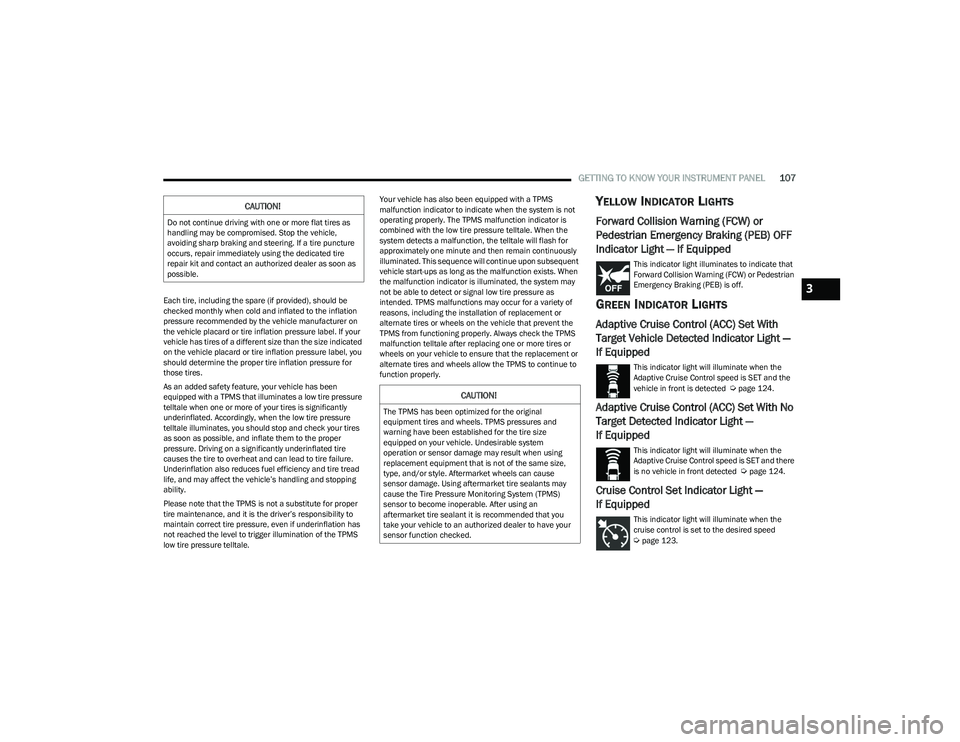
This indicator light illuminates to indicate that
Forward Collision Warning (FCW) or Pedestrian
Emergency Braking (PEB) is off.
GREEN INDICATOR LIGHTS
Adaptive Cruise Control (ACC) Set With
Target Vehicle Detected Indicator Light —
If Equipped
This indicator light will illuminate when the
Adaptive Cruise Control speed is SET and the
vehicle in front is detected
Úpage 124.
Adaptive Cruise Control (ACC) Set With No
Target Detected Indicator Light —
If Equipped
This indicator light will illuminate when the
Adaptive Cruise Control speed is SET and there
is no vehicle in front detected
Úpage 124.
Cruise Control Set Indicator Light —
If Equipped
This indicator light will illuminate when the
cruise control is set to the desired speed
Úpage 123.
CAUTION!
Do not continue driving with one or more flat tires as
handling may be compromised. Stop the vehicle,
avoiding sharp braking and steering. If a tire puncture
occurs, repair immediately using the dedicated tire
repair kit and contact an authorized dealer as soon as
possible.
CAUTION!
The TPMS has been optimized for the original
equipment tires and wheels. TPMS pressures and
warning have been established for the tire size
equipped on your vehicle. Undesirable system
operation or sensor damage may result when using
replacement equipment that is not of the same size,
type, and/or style. Aftermarket wheels can cause
sensor damage. Using aftermarket tire sealants may
cause the Tire Pressure Monitoring System (TPMS)
sensor to become inoperable. After using an
aftermarket tire sealant it is recommended that you
take your vehicle to an authorized dealer to have your
sensor function checked.
3
23_RUP_OM_EN_USC_t.book Page 107
Page 149 of 328
STARTING AND OPERATING147
Each axle GAWR is determined by the components in the
system with the lowest load carrying capacity (axle,
springs, tires or wheels). Heavier axles or suspension
components sometimes specified by purchasers for
increased durability do not necessarily increase the
vehicle's GVWR.
Tire Size
The tire size on the Vehicle Certification Label represents
the actual tire size on your vehicle. Replacement tires
must be equal to the load capacity of this tire size.
Rim Size
This is the rim size that is appropriate for the tire size
listed.
Inflation Pressure
This is the cold tire inflation pressure for your vehicle for
all loading conditions up to full GAWR.
Curb Weight
The curb weight of a vehicle is defined as the total weight
of the vehicle with all fluids, including vehicle fuel, at full
capacity conditions, and with no occupants or cargo
loaded into the vehicle. The front and rear curb weight
values are determined by weighing your vehicle on a
commercial scale before any occupants or cargo are
added.
Loading
The actual total weight and the weight of the front and rear
of your vehicle at the ground can best be determined by
weighing it when it is loaded and ready for operation.
The entire vehicle should first be weighed on a commercial
scale to ensure that the GVWR has not been exceeded.
The weight on the front and rear of the vehicle should then
be determined separately to be sure that the load is
properly distributed over the front and rear axle. Weighing
the vehicle may show that the GAWR of either the front or
rear axles has been exceeded but the total load is within
the specified GVWR. If so, weight must be shifted from
front to rear or rear to front as appropriate until the
specified weight limitations are met. Store the heavier
items down low and be sure that the weight is distributed
equally. Stow all loose items securely before driving.
Improper weight distributions can have an adverse effect
on the way your vehicle steers and handles and the way
the brakes operate.TRAILER TOWING
NOTE:Trailer towing is not permitted for the Plug-in Hybrid
Electric Vehicle (PHEV).
In this section you will find safety tips and information on
limits to the type of towing you can reasonably do with your
vehicle. Before towing a trailer, carefully review this
information to tow your load as efficiently and safely as
possible.
To maintain the New Vehicle Limited Warranty coverage,
follow the requirements and recommendations in this
manual concerning vehicles used for trailer towing.
COMMON TOWING DEFINITIONS
The following trailer towing related definitions will assist
you in understanding the following information:
Gross Vehicle Weight Rating (GVWR)
GVWR is the total allowable weight of your vehicle. This
includes driver, passengers, cargo and tongue weight. The
total load must be limited so that you do not exceed the
GVWR
Úpage 146.
WARNING!
Do not load your vehicle any heavier than the GVWR or
the maximum front and rear GAWR. If you do, parts on
your vehicle can break, or it can change the way your
vehicle handles. This could cause you to lose control.
Overloading can shorten the life of your vehicle.
4
23_RUP_OM_EN_USC_t.book Page 147
Page 154 of 328
152STARTING AND OPERATING
Towing Requirements — Tires
Do not attempt to tow a trailer while using a compact
spare tire.
Do not drive more than 50 mph (80 km/h) when towing
while using a full size spare tire.
Proper tire inflation pressures are essential to the safe
and satisfactory operation of your vehicle.
Check the trailer tires for proper tire inflation pressures
before trailer usage.
Check for signs of tire wear or visible tire damage
before towing a trailer.
Replacing tires with a higher load carrying capacity will
not increase the vehicle's GVWR and GAWR limits.
For further information
Úpage 291.
Towing Requirements — Trailer Brakes
Do not interconnect the hydraulic brake system or
vacuum system of your vehicle with that of the trailer.
This could cause inadequate braking and possible
personal injury.
An electronically actuated trailer brake controller is
required when towing a trailer with electronically actu -
ated brakes. When towing a trailer equipped with a
hydraulic surge actuated brake system, an electronic
brake controller is not required.
Trailer brakes are recommended for trailers over
1,000 lb (453 kg) and required for trailers in excess of
2,000 lb (907 kg).
Towing Requirements — Trailer Lights And
Wiring
Whenever you pull a trailer, regardless of the trailer size,
stop lights and turn signals on the trailer are required for
motoring safety.
The Trailer Tow Package may include a four and seven-pin
wiring harness. Use a factory approved trailer harness and
connector.
NOTE:Do not cut or splice wiring into the vehicle’s wiring
harness.
WARNING!
Do not connect trailer brakes to your vehicle's
hydraulic brake lines. It can overload your brake
system and cause it to fail. You might not have brakes
when you need them and could have an accident.
Towing any trailer will increase your stopping distance.
When towing, you should allow for additional space
between your vehicle and the vehicle in front of you.
Failure to do so could result in an accident.
CAUTION!
If the trailer weighs more than 1,000 lb (453 kg)
loaded, it should have its own brakes and they should
be of adequate capacity. Failure to do this could lead to
accelerated brake lining wear, higher brake pedal
effort, and longer stopping distances.
23_RUP_OM_EN_USC_t.book Page 152
Page 199 of 328
SAFETY197
This indicates there is an internal system fault. Although
the vehicle is still drivable under normal conditions, have
the system checked by an authorized dealer.
Pedestrian Emergency Braking (PEB) —
If Equipped
PEB is a subsystem of the FCW system which provides the
driver with audible and visual warnings in the instrument
cluster display, and may apply automatic braking when it
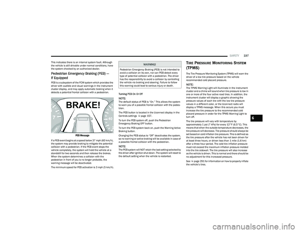
detects a potential frontal collision with a pedestrian.
PEB Message
If a PEB event begins at a speed below 37 mph (60 km/h),
the system may provide braking to mitigate the potential
collision with a pedestrian. If the PEB event stops the
vehicle completely, the system will hold the vehicle at a
standstill for two seconds and then release the brakes.
When the system determines a collision with the
pedestrian in front of you is no longer probable, the
warning message will be deactivated.
The minimum speed for PEB activation is 3 mph (5 km/h). Turning PEB On Or Off
NOTE:The default status of PEB is “On.” This allows the system
to warn you of a possible frontal collision with the pedes
-
trian.
The PEB button is located in the Uconnect display in the
Controls settings
Úpage 157.
To turn the PEB system off, push the Pedestrian
Emergency Braking OFF button.
To turn the PEB system back on, push the Warning Active
Braking button.
Changing the PEB status to “Off” deactivates the system,
so no warning or active braking will be available in case of
a possible frontal collision with the pedestrian.
NOTE:The PEB system will NOT retain the last setting selected by
the driver after ignition shut down. The system will reset to
the default setting when the vehicle is restarted.
TIRE PRESSURE MONITORING SYSTEM
(TPMS)
The Tire Pressure Monitoring System (TPMS) will warn the
driver of a low tire pressure based on the vehicle
recommended cold placard pressure.
NOTE:The TPMS Warning Light will illuminate in the instrument
cluster and a chime will sound when tire pressure is low in
one or more of the four active road tires. In addition, the
instrument cluster will display a graphic showing the
pressure values of each tire with the low tire pressure
values in a different color, or the Uconnect radio will
display a TPMS message. When this occurs you must
increase the tire pressure to the recommended cold
placard pressure in order for the TPMS Warning Light to
turn off.
The tire pressure will vary with temperature by
approximately 1 psi (7 kPa) for every 12°F (6.5°C). This
means that when the outside temperature decreases, the
tire pressure will decrease. Tire pressure should always be
set based on cold inflation tire pressure. This is defined as
the tire pressure after the vehicle has not been driven for
at least three hours, or driven less than 1 mile (1.6 km)
after a three hour period. The cold tire inflation pressure
must not exceed the maximum inflation pressure molded
into the tire sidewall. The tire pressure will also increase
as the vehicle is driven. This is normal and there should be
no adjustment for this increased pressure.
See
Úpage 291 for information on how to properly inflate
the vehicle’s tires.
WARNING!
Pedestrian Emergency Braking (PEB) is not intended to
avoid a collision on its own, nor can PEB detect every
type of potential collision with a pedestrian. The driver
has the responsibility to avoid a collision by controlling
the vehicle via braking and steering. Failure to follow
this warning could lead to serious injury or death.
6
23_RUP_OM_EN_USC_t.book Page 197
Page 200 of 328
198SAFETY
The TPMS will warn the driver of a low tire pressure if the
tire pressure falls below the low-pressure warning limit for
any reason, including low temperature effects and natural
pressure loss through the tire.
The TPMS will continue to warn the driver of low tire
pressure as long as the condition exists, and will not turn
off until the tire pressure is at or above the recommended
cold placard pressure. Once the low tire pressure warning
(TPMS Warning Light) illuminates, you must increase the
tire pressure to the recommended cold placard pressure
in order for the TPMS Warning Light to turn off.
The system will automatically update and the TPMS
Warning Light will turn off once the system receives the
updated tire pressures. The vehicle may need to be driven
for up to 20 minutes above 15 mph (24 km/h) in order for
the TPMS to receive this information.
For example, your vehicle may have a recommended cold
(parked for more than three hours) placard pressure of
33 psi (227 kPa). If the ambient temperature is 68°F
(20°C) and the measured tire pressure is 28 psi
(193 kPa), a temperature drop to 20°F (-7°C) will
decrease the tire pressure to approximately 24 psi
(165 kPa). This tire pressure is low enough to turn on the
TPMS Warning Light. Driving the vehicle may cause the tire
pressure to rise to approximately 28 psi (193 kPa), but the
TPMS Warning Light will still be on. In this situation, the
TPMS Warning Light will turn off only after the tires are
inflated to the vehicle’s recommended cold placard
pressure value
Úpage 312.
NOTE:When filling warm tires, the tire pressure may need to be
increased up to an additional 4 psi (28 kPa) above the
recommended cold placard pressure in order to turn the
TPMS Warning Light off.NOTE:
The TPMS is not intended to replace normal tire care
and maintenance, or to provide warning of a tire failure
or condition.
The TPMS should not be used as a tire pressure gauge
while adjusting your tire pressure.
Driving on a significantly underinflated tire causes the
tire to overheat and can lead to tire failure. Underinfla -
tion also reduces fuel efficiency and tire tread life, and
may affect the vehicle’s handling and stopping ability.
The TPMS is not a substitute for proper tire mainte -
nance, and it is the driver’s responsibility to maintain
correct tire pressure using an accurate tire pressure
gauge, even if underinflation has not reached the level
to trigger illumination of the TPMS Warning Light.
Seasonal temperature changes will affect tire pres -
sure, and the TPMS will monitor the actual tire pres -
sure in the tire.
Premium System
The Tire Pressure Monitoring System (TPMS) uses wireless
technology with wheel rim mounted electronic sensors to
monitor tire pressure levels. Sensors, mounted to each
wheel as part of the valve stem, transmit tire pressure
readings to the receiver module.
NOTE:It is particularly important for you to check the tire
pressure in all of the tires on your vehicle monthly and to
maintain the proper pressure.
CAUTION!
The TPMS has been optimized for the original equip -
ment tires and wheels. TPMS pressures and warning
have been established for the tire size equipped on
your vehicle. Undesirable system operation or sensor
damage may result when using replacement equip -
ment that is not of the same size, type, and/or style.
The TPMS sensor is not designed for use on after -
market wheels and may contribute to a poor overall
system performance or sensor damage. Customers
are encouraged to use Original Equipment Manufac -
turer (OEM) wheels to ensure proper TPMS feature
operation.
Using aftermarket tire sealants may cause the Tire
Pressure Monitoring System (TPMS) sensor to
become inoperable. After using an aftermarket tire
sealant it is recommended that you take your vehicle
to an authorized dealer to have your sensor function
checked.
After inspecting or adjusting the tire pressure always
reinstall the valve stem cap. This will prevent mois -
ture and dirt from entering the valve stem, which
could damage the TPMS sensor.
23_RUP_OM_EN_USC_t.book Page 198
Page 236 of 328

234SAFETY
(Continued)
(Continued)
Defroster
Check operation by selecting the defrost mode and place
the blower control on high speed. You should be able to
feel the air directed against the windshield. See an
authorized dealer for service if your defroster is
inoperable.
Floor Mat Safety Information
Always use floor mats designed to fit your vehicle. Only use
a floor mat that does not interfere with the operation of the
accelerator, brake or clutch pedals. Only use a floor mat
that is securely attached using the floor mat fasteners so
it cannot slip out of position and interfere with the
accelerator, brake or clutch pedals or impair safe
operation of your vehicle in other ways.
PERIODIC SAFETY CHECKS YOU SHOULD
M
AKE OUTSIDE THE VEHICLE
Tires
Examine tires for excessive tread wear and uneven wear
patterns. Check for stones, nails, glass, or other objects
lodged in the tread or sidewall. Inspect the tread for cuts
and cracks. Inspect sidewalls for cuts, cracks, and bulges.
Check the lug nut/bolt torque for tightness. Check the
tires (including spare) for proper cold inflation pressure.
WARNING!
An improperly attached, damaged, folded, or stacked
floor mat, or damaged floor mat fasteners may cause
your floor mat to interfere with the accelerator, brake, or
clutch pedals and cause a loss of vehicle control. To
prevent SERIOUS INJURY or DEATH:
ALWAYS securely attach your floor mat
using the floor mat fasteners. DO NOT
install your floor mat upside down or turn
your floor mat over. Lightly pull to confirm
mat is secured using the floor mat
fasteners on a regular basis.
ALWAYS REMOVE THE EXISTING FLOOR
MAT FROM THE VEHICLE before installing
any other floor mat. NEVER install or stack
an additional floor mat on top of an existing
floor mat.
ONLY install floor mats designed to fit your vehicle.
NEVER install a floor mat that cannot be properly
attached and secured to your vehicle. If a floor mat
needs to be replaced, only use a FCA US LLC
approved floor mat for the specific make, model, and
year of your vehicle.
ONLY use the driver’s side floor mat on the driver’s
side floor area. To check for interference, with the
vehicle properly parked with the engine off, fully
depress the accelerator, the brake, and the clutch
pedal (if present) to check for interference. If your
floor mat interferes with the operation of any pedal,
or is not secure to the floor, remove the floor mat
from the vehicle and place the floor mat in your
trunk.
ONLY use the passenger’s side floor mat on the
passenger’s side floor area.
ALWAYS make sure objects cannot fall or slide into
the driver’s side floor area when the vehicle is
moving. Objects can become trapped under acceler -
ator, brake, or clutch pedals and could cause a loss
of vehicle control.
WARNING!
NEVER place any objects under the floor mat (e.g.,
towels, keys, etc.). These objects could change the
position of the floor mat and may cause interference
with the accelerator, brake, or clutch pedals.
If the vehicle carpet has been removed and
re-installed, always properly attach carpet to the floor
and check the floor mat fasteners are secure to the
vehicle carpet. Fully depress each pedal to check for
interference with the accelerator, brake, or clutch
pedals then re-install the floor mats.
It is recommended to only use mild soap and water
to clean your floor mats. After cleaning, always check
your floor mat has been properly installed and is
secured to your vehicle using the floor mat fasteners
by lightly pulling mat.
WARNING!
23_RUP_OM_EN_USC_t.book Page 234
Page 245 of 328
IN CASE OF EMERGENCY243
Mounting Inflatable Spare Tire
NOTE:
Do not install the wheel cover on the inflatable spare tire.
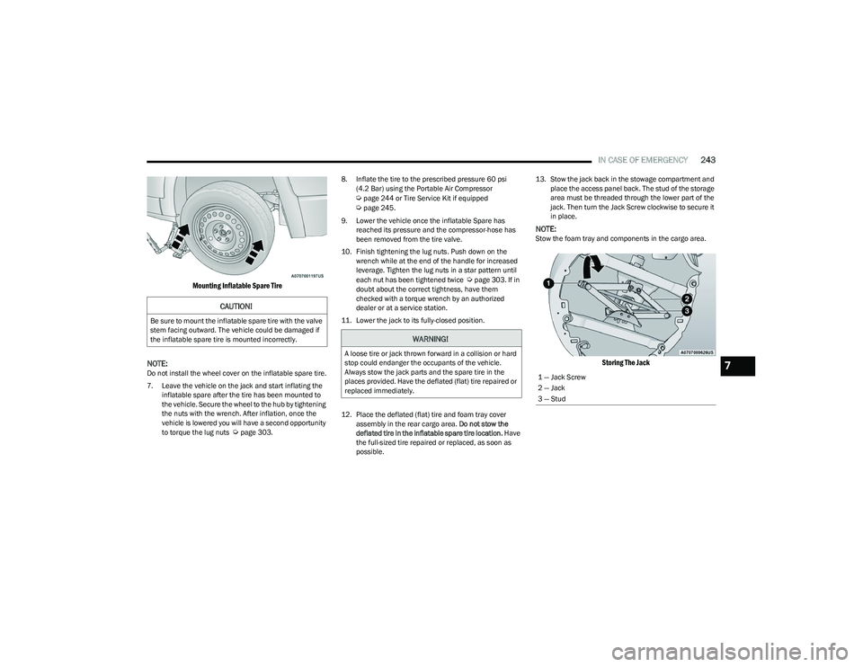
7. Leave the vehicle on the jack and start inflating the inflatable spare after the tire has been mounted to
the vehicle. Secure the wheel to the hub by tightening
the nuts with the wrench. After inflation, once the
vehicle is lowered you will have a second opportunity
to torque the lug nuts
Úpage 303. 8. Inflate the tire to the prescribed pressure 60 psi
(4.2 Bar) using the Portable Air Compressor
Úpage 244 or Tire Service Kit if equipped Úpage 245.
9. Lower the vehicle once the inflatable Spare has reached its pressure and the compressor-hose has
been removed from the tire valve.
10. Finish tightening the lug nuts. Push down on the wrench while at the end of the handle for increased
leverage. Tighten the lug nuts in a star pattern until
each nut has been tightened twice
Úpage 303. If in
doubt about the correct tightness, have them
checked with a torque wrench by an authorized
dealer or at a service station.
11. Lower the jack to its fully-closed position.
12. Place the deflated (flat) tire and foam tray cover assembly in the rear cargo area. Do not stow the
deflated tire in the inflatable spare tire location. Have
the full-sized tire repaired or replaced, as soon as
possible. 13. Stow the jack back in the stowage compartment and
place the access panel back. The stud of the storage
area must be threaded through the lower part of the
jack. Then turn the Jack Screw clockwise to secure it
in place.
NOTE:Stow the foam tray and components in the cargo area.
Storing The Jack
CAUTION!
Be sure to mount the inflatable spare tire with the valve
stem facing outward. The vehicle could be damaged if
the inflatable spare tire is mounted incorrectly.
WARNING!
A loose tire or jack thrown forward in a collision or hard
stop could endanger the occupants of the vehicle.
Always stow the jack parts and the spare tire in the
places provided. Have the deflated (flat) tire repaired or
replaced immediately.
1 — Jack Screw
2 — Jack
3 — Stud7
23_RUP_OM_EN_USC_t.book Page 243
Page 251 of 328
IN CASE OF EMERGENCY249
2. The pump will start to inject air into the
tire immediately after the Sealant Bottle
is empty. Continue to operate the pump
and inflate the tire to the cold tire
inflation pressure found on the tire and
loading information label located in the driver-side
door opening. Check the tire pressure by looking at
the Pressure Gauge.
If the tire does not inflate to at least 26 psi (1.8 bar) within
15 minutes:
The tire is too badly damaged. Do not attempt to drive
the vehicle further. Call for assistance.
If the tire inflates to the recommended pressure or is at
least 26 psi (1.8 bar) within 15 minutes:
NOTE:If the tire becomes overinflated, push the Deflation Button
to reduce the tire pressure to the recommended inflation
pressure before continuing.
1. Push the Power Button to turn the Tire
Service Kit off.
2. Remove the speed limit label from the
Tire Service Kit and place sticker on the
steering wheel.
3. Immediately disconnect the Sealant Hose from the valve stem, reinstall the cap on the fitting at the end
of the hose, and place the Tire Service Kit in the
vehicle storage location. Drive Vehicle:
Immediately after injecting sealant and
inflating the tire, drive the vehicle 5 miles
(8 km) or 10 minutes to ensure distribution of
the Tire Service Kit Sealant within the tire. Do
not exceed 50 mph (80 km/h).
After Driving:
Pull over to a safe location and turn on the vehicle’s
Hazard Warning Flashers.
Verify that the valve stem (on the wheel with the
deflated tire) is in a position that is near to the ground.
This will allow the Tire Service Kit Hose to reach the
valve stem and keep the Tire Service Kit flat on the
ground. This will provide the best positioning of the kit
when injecting the sealant into the deflated tire and
running the air pump. Move the vehicle as necessary to
place the valve stem in this position before proceeding.
Place the transmission in PARK (P) and cycle the igni -
tion in the OFF position.
Apply the parking brake.
NOTE:If tire has improper inflation follow these next steps:
1. Uncoil the Sealant Hose, and then remove the cap
from the fitting at the end of the hose.
2. Place the Tire Service Kit flat on the
ground next to the deflated tire.
3. Remove the cap from the valve stem, and then screw the fitting at the end of the Sealant Hose onto the
valve stem.
4. Uncoil the Power Plug and insert the
plug into the vehicle's 12 Volt power
outlet.
5. Uncoil the Hose and screw the fitting at
the end of the hose onto the valve stem.
6. Turn the Mode Select Knob and turn to
the Air Mode position.
7. Check the pressure in the tire by reading the Pressure Gauge.
If tire pressure is less than 19 psi (1.3 bar):
The tire is too badly damaged. Do not attempt to drive the
vehicle further. Call for assistance.
WARNING!
The Tire Service Kit is not a permanent flat tire repair.
Have the tire inspected and repaired or replaced after
using the Tire Service Kit. Do not exceed 50 mph
(80 km/h) until the tire is repaired or replaced. Failure
to follow this warning can result in injuries that are
serious or fatal to you, your passengers, and others
around you. Have the tire checked as soon as possible
at an authorized dealer.
7
23_RUP_OM_EN_USC_t.book Page 249
Page 252 of 328
250IN CASE OF EMERGENCY
If the tire pressure is 19 psi (1.3 bar) or higher:
1. Push the Power Button to turn on Tire
Service Kit and inflate the tire to the cold
tire inflation pressure found on the tire
and loading information label located in
the driver-side door opening.
NOTE:If the tire becomes overinflated, push the Deflation Button
to reduce the tire pressure to the recommended inflation
pressure before continuing.
2. Disconnect the Tire Service Kit from the valve stem, reinstall the cap on the valve stem and unplug from
12 Volt outlet.
3. Place the Tire Service Kit in its proper storage area in the vehicle.
4. Have the tire inspected and repaired or replaced at the earliest opportunity at an authorized dealer or tire
service center.
5. Remove the Speed Limit sticker from the steering wheel after the tire has been repaired.
6. Replace the Sealant Bottle at an authorized dealer as soon as possible.
NOTE:When having the tire serviced, advise the authorized
dealer or service center that the tire has been sealed
using the Tire Service Kit.
Sealant Bottle Replacement:
1. Unwrap the power cord.
2. Unwrap the hose.
Hose Location
3. Remove the bottle cover.
Remove The Bottle Cover
4. Rotate the bottle up beyond vertical to release.
Rotate The Bottle Up
5. Pull the bottle away from the Compressor.
Remove The Bottle
NOTE:
For sealant bottle installation, follow these steps
reverse order.
Replacement sealant bottles are available at autho -
rized service centers.
23_RUP_OM_EN_USC_t.book Page 250
Page 287 of 328
SERVICING AND MAINTENANCE285
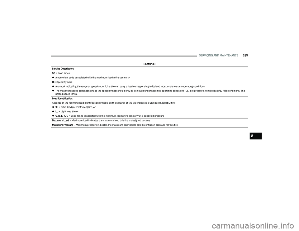
Service Description:
95 = Load Index
A numerical code associated with the maximum load a tire can carry
H = Speed Symbol
A symbol indicating the range of speeds at which a tire can carry a load corresponding to its load index under certain operating conditions
The maximum speed corresponding to the speed symbol should only be achieved under specified operating conditions (i.e., tire pressure, vehicle loading, road conditions, and
posted speed limits)
Load Identification:
Absence of the following load identification symbols on the sidewall of the tire indicates a Standard Load (SL) tire:
XL = Extra load (or reinforced) tire, or
LL = Light load tire or
C, D, E, F, G = Load range associated with the maximum load a tire can carry at a specified pressure
Maximum Load – Maximum load indicates the maximum load this tire is designed to carry
Maximum Pressure – Maximum pressure indicates the maximum permissible cold tire inflation pressure for this tire
EXAMPLE:
8
23_RUP_OM_EN_USC_t.book Page 285