length CHRYSLER PACIFICA HYBRID 2017 2.G Owners Manual
[x] Cancel search | Manufacturer: CHRYSLER, Model Year: 2017, Model line: PACIFICA HYBRID, Model: CHRYSLER PACIFICA HYBRID 2017 2.GPages: 592, PDF Size: 6.73 MB
Page 89 of 592
NOTE:
•The head restraints must be raised manually when
occupying the third row.
• Do not fold if there are passengers seated in the third
row seats.
The head restraint in the center position can be raised and
lowered for tether routing or height adjustment. Refer to
“Occupant Restraint Systems” in “Safety” for further infor-
mation.
STEERING WHEEL
Tilt/Telescoping Steering Column
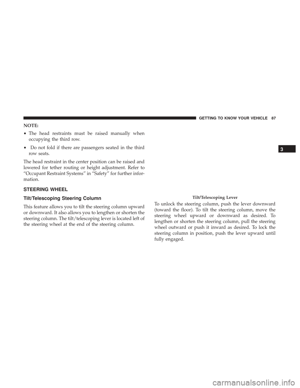
This feature allows you to tilt the steering column upward
or downward. It also allows you to lengthen or shorten the
steering column. The tilt/telescoping lever is located left of
the steering wheel at the end of the steering column. To unlock the steering column, push the lever downward
(toward the floor). To tilt the steering column, move the
steering wheel upward or downward as desired. To
lengthen or shorten the steering column, pull the steering
wheel outward or push it inward as desired. To lock the
steering column in position, push the lever upward until
fully engaged.
Tilt/Telescoping Lever
3
GETTING TO KNOW YOUR VEHICLE 87
Page 143 of 592
WARNING!
To avoid serious injury or death:
•Only devices designed for use in this type of outlet
should be inserted into any 12 Volt outlet.
• Do not touch with wet hands.
(Continued)
WARNING! (Continued)
•Close the lid when not in use and while driving the
vehicle.
• If this outlet is mishandled, it may cause an electric
shock and failure.
CAUTION!
• Many accessories that can be plugged in draw power
from the vehicle’s battery, even when not in use (i.e.,
cellular phones, etc.). Eventually, if plugged in long
enough, the vehicle’s battery will discharge suffi-
ciently to degrade battery life and/or prevent the
vehicle from starting.
• Accessories that draw higher power (i.e., coolers,
vacuum cleaners, lights, etc.) will degrade the battery
even more quickly. Only use these intermittently and
with greater caution.
• After the use of high power draw accessories, or long
periods of the vehicle not being started (with acces-
sories still plugged in), the vehicle must be driven a
sufficient length of time to allow the generator to
recharge the vehicle’s battery or plug the vehicle in
with EVSE charger.
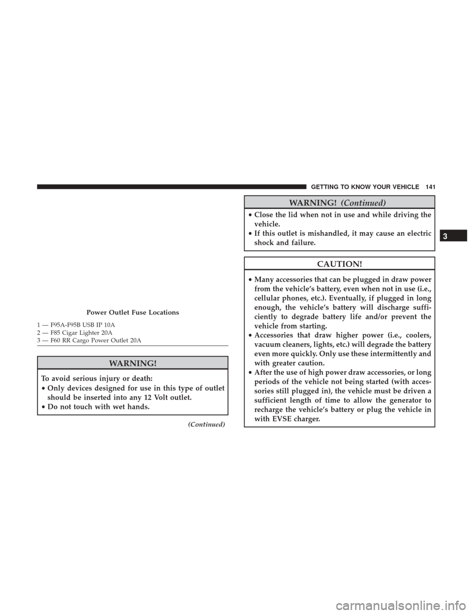
Power Outlet Fuse Locations
1 — F95A-F95B USB IP 10A
2 — F85 Cigar Lighter 20A
3 — F60 RR Cargo Power Outlet 20A
3
GETTING TO KNOW YOUR VEHICLE 141
Page 205 of 592
AUXILIARY DRIVING SYSTEMS
Blind Spot Monitoring (BSM) — If Equipped
The Blind Spot Monitoring (BSM) system uses two radar-
based sensors, located inside the rear bumper fascia, to
detect highway licensable vehicles (automobiles, trucks,
motorcycles, etc.) that enter the blind spot zones from the
rear/front/side of the vehicle.
When the vehicle is started, the BSM warning light will
momentarily illuminate in both outside rear view mirrors
to let the driver know that the system is operational. TheBSM system sensors operate when the vehicle is in any
forward gear or REVERSE and enters stand-by mode when
the vehicle is in PARK.
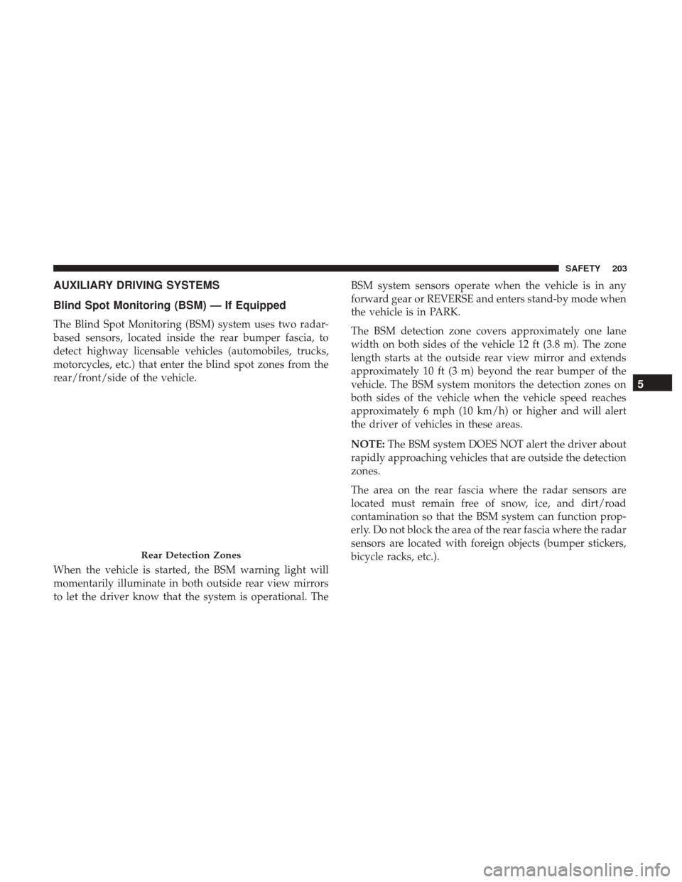
The BSM detection zone covers approximately one lane
width on both sides of the vehicle 12 ft (3.8 m). The zone
length starts at the outside rear view mirror and extends
approximately 10 ft (3 m) beyond the rear bumper of the
vehicle. The BSM system monitors the detection zones on
both sides of the vehicle when the vehicle speed reaches
approximately 6 mph (10 km/h) or higher and will alert
the driver of vehicles in these areas.
NOTE:
The BSM system DOES NOT alert the driver about
rapidly approaching vehicles that are outside the detection
zones.
The area on the rear fascia where the radar sensors are
located must remain free of snow, ice, and dirt/road
contamination so that the BSM system can function prop-
erly. Do not block the area of the rear fascia where the radar
sensors are located with foreign objects (bumper stickers,
bicycle racks, etc.).
Rear Detection Zones
5
SAFETY 203
Page 427 of 592
CAUTION!
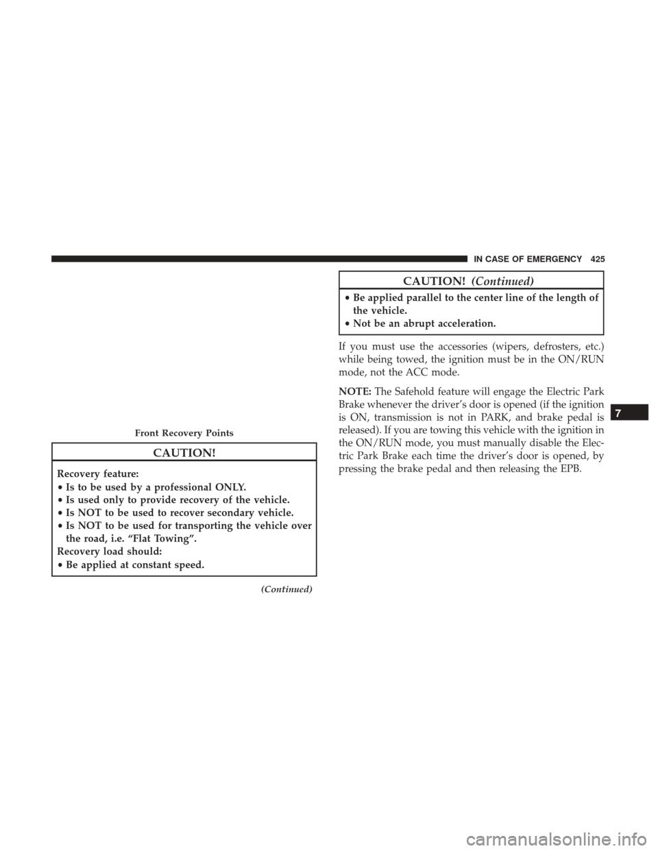
Recovery feature:
•Is to be used by a professional ONLY.
• Is used only to provide recovery of the vehicle.
• Is NOT to be used to recover secondary vehicle.
• Is NOT to be used for transporting the vehicle over
the road, i.e. “Flat Towing”.
Recovery load should:
• Be applied at constant speed.
(Continued)
CAUTION! (Continued)
•Be applied parallel to the center line of the length of
the vehicle.
• Not be an abrupt acceleration.
If you must use the accessories (wipers, defrosters, etc.)
while being towed, the ignition must be in the ON/RUN
mode, not the ACC mode.
NOTE: The Safehold feature will engage the Electric Park
Brake whenever the driver’s door is opened (if the ignition
is ON, transmission is not in PARK, and brake pedal is
released). If you are towing this vehicle with the ignition in
the ON/RUN mode, you must manually disable the Elec-
tric Park Brake each time the driver’s door is opened, by
pressing the brake pedal and then releasing the EPB.
Front Recovery Points
7
IN CASE OF EMERGENCY 425
Page 505 of 592
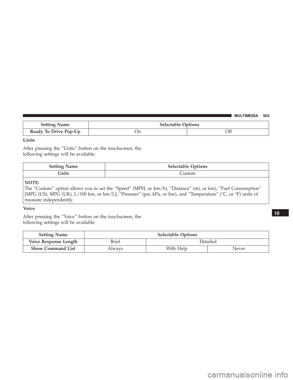
Setting NameSelectable Options
Ready To Drive Pop-Up OnOff
Units
After pressing the “Units” button on the touchscreen, the
following settings will be available:
Setting Name Selectable Options
Units Custom
NOTE:
The “Custom” option allows you to set the “Speed” (MPH, or km/h), “Distance” (mi, or km), “Fuel Consumption”
[MPG (US), MPG (UK), L/100 km, or km/L], “Pressure” (psi, kPa, or bar), and “Temperature” (°C, or °F) units of
measure independently.
Voice
After pressing the “Voice” button on the touchscreen, the
following settings will be available:
Setting Name Selectable Options
Voice Response Length Brief Detailed
Show Command List AlwaysWith Help Never
10
MULTIMEDIA 503