warning light CHRYSLER PACIFICA HYBRID 2018 Owners Manual
[x] Cancel search | Manufacturer: CHRYSLER, Model Year: 2018, Model line: PACIFICA HYBRID, Model: CHRYSLER PACIFICA HYBRID 2018Pages: 614, PDF Size: 7.08 MB
Page 20 of 614
HIGH VOLTAGE BATTERY
Your vehicle is equipped with a Lithium-ion high voltage
battery that is used to power the electric powertrain
systems and the 12 volt vehicle electrical system.
The high voltage battery is located under the middle
section of the vehicle, below and in front of the second row
seating. The high voltage battery is maintenance free and
designed to last for the life of the vehicle.
Lithium-ion batteries provide the following benefits:
•Lithium-ion batteries are much lighter than other types
of rechargeable batteries of the same size.
• Lithium-ion batteries hold their charge; they only lose
approximately 3 percent of their charge per month.
• Lithium-ion batteries have no memory, which means
that you do not have to completely discharge them
before recharging, as with some other batteries.
• Lithium-ion batteries can be recharged and discharged
thousands of times. High Voltage Battery Service Disconnect
The High Voltage Battery Service Disconnect is located
under the access panel, in front of the second row passen-
ger seating.
If your vehicle requires high voltage battery service, see
your authorized dealer.
WARNING!
Never try to remove the high voltage service discon-
nect. The high voltage service disconnect is used when
your vehicle requires service by a trained technician at
an authorized dealer. Failure to follow this warning
can cause severe burns or electrical shock that may
result in serious injury or death.
Disposal of the High Voltage Battery
Your vehicle’s high voltage battery is designed to last the
life of your vehicle. See your authorized dealer for infor-
mation on the disposal of the battery if it should require
replacement.
18 GETTING TO KNOW YOUR VEHICLE
Page 26 of 614
Charging Cordset Operation
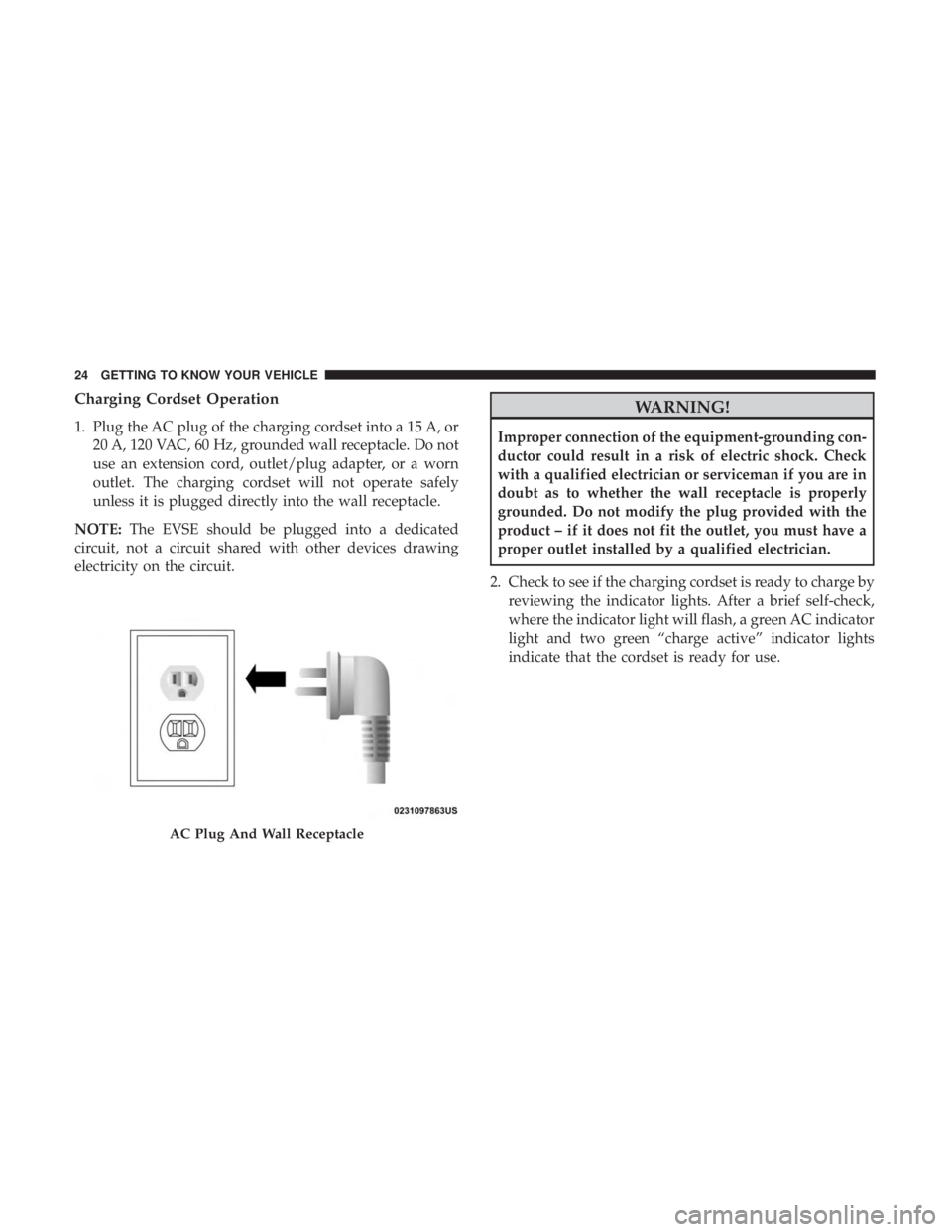
1. Plug the AC plug of the charging cordset into a 15 A, or20 A, 120 VAC, 60 Hz, grounded wall receptacle. Do not
use an extension cord, outlet/plug adapter, or a worn
outlet. The charging cordset will not operate safely
unless it is plugged directly into the wall receptacle.
NOTE: The EVSE should be plugged into a dedicated
circuit, not a circuit shared with other devices drawing
electricity on the circuit.
WARNING!
Improper connection of the equipment-grounding con-
ductor could result in a risk of electric shock. Check
with a qualified electrician or serviceman if you are in
doubt as to whether the wall receptacle is properly
grounded. Do not modify the plug provided with the
product – if it does not fit the outlet, you must have a
proper outlet installed by a qualified electrician.
2. Check to see if the charging cordset is ready to charge by reviewing the indicator lights. After a brief self-check,
where the indicator light will flash, a green AC indicator
light and two green “charge active” indicator lights
indicate that the cordset is ready for use.
AC Plug And Wall Receptacle
24 GETTING TO KNOW YOUR VEHICLE
Page 72 of 614
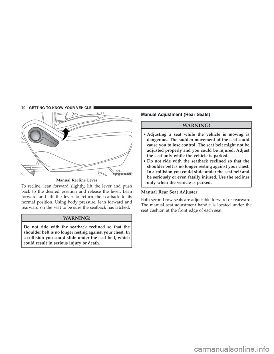
To recline, lean forward slightly, lift the lever and push
back to the desired position and release the lever. Lean
forward and lift the lever to return the seatback to its
normal position. Using body pressure, lean forward and
rearward on the seat to be sure the seatback has latched.
WARNING!
Do not ride with the seatback reclined so that the
shoulder belt is no longer resting against your chest. In
a collision you could slide under the seat belt, which
could result in serious injury or death.
Manual Adjustment (Rear Seats)
WARNING!
•Adjusting a seat while the vehicle is moving is
dangerous. The sudden movement of the seat could
cause you to lose control. The seat belt might not be
adjusted properly and you could be injured. Adjust
the seat only while the vehicle is parked.
• Do not ride with the seatback reclined so that the
shoulder belt is no longer resting against your chest.
In a collision you could slide under the seat belt and
be seriously or even fatally injured. Use the recliner
only when the vehicle is parked.
Manual Rear Seat Adjuster
Both second row seats are adjustable forward or rearward.
The manual seat adjustment handle is located under the
seat cushion at the front edge of each seat.
Manual Recline Lever
70 GETTING TO KNOW YOUR VEHICLE
Page 73 of 614
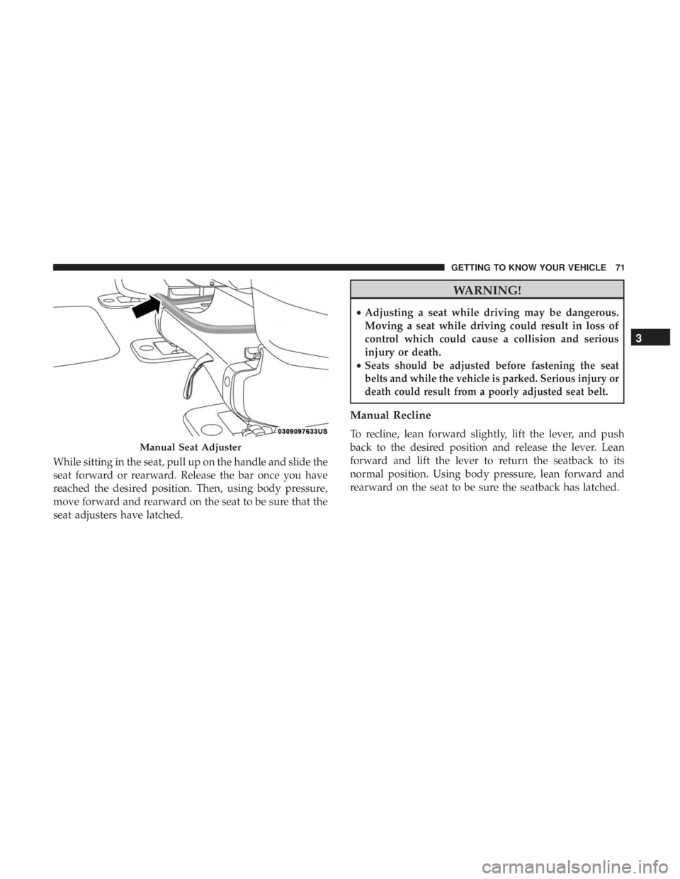
While sitting in the seat, pull up on the handle and slide the
seat forward or rearward. Release the bar once you have
reached the desired position. Then, using body pressure,
move forward and rearward on the seat to be sure that the
seat adjusters have latched.
WARNING!
•Adjusting a seat while driving may be dangerous.
Moving a seat while driving could result in loss of
control which could cause a collision and serious
injury or death.
•
Seats should be adjusted before fastening the seat
belts and while the vehicle is parked. Serious injury or
death could result from a poorly adjusted seat belt.
Manual Recline
To recline, lean forward slightly, lift the lever, and push
back to the desired position and release the lever. Lean
forward and lift the lever to return the seatback to its
normal position. Using body pressure, lean forward and
rearward on the seat to be sure the seatback has latched.
Manual Seat Adjuster
3
GETTING TO KNOW YOUR VEHICLE 71
Page 76 of 614
WARNING!
•Adjusting a seat while driving may be dangerous.
Moving a seat while driving could result in loss of
control which could cause a collision and serious
injury or death.
• Seats should be adjusted before fastening the seat
belts and while the vehicle is parked. Serious injury
or death could result from a poorly adjusted seat belt.
• Do not ride with the seatback reclined so that the
shoulder belt is no longer resting against your chest.
In a collision you could slide under the seat belt,
which could result in serious injury or death.
CAUTION!
Do not place any article under a power seat or impede
its ability to move as it may cause damage to the seat
controls. Seat travel may become limited if movement
is stopped by an obstruction in the seat’s path.
Power Lumbar — If Equipped
Vehicles equipped with power driver or passenger seats
may be equipped with power lumbar. The power lumbar
switch is located on the outboard side of the power seat. Push the switch forward or rearward to increase or de-
crease the lumbar support. Push the switch upward or
downward to raise or lower the lumbar support.
Heated Seats
Front Heated Seats — If Equipped
The front heated seats control buttons are located within
the climate or controls screen of the touchscreen.
You can choose from HI, LO, or OFF heat settings. The
indicator lights in each switch indicate the level of heat in
use. Two indicator lights will illuminate for HI, one for LO
and none for OFF.
•
Press the heated seat button
once to turn the HI
setting ON.
• Press the heated seat buttona second time to turn
the LO setting ON.
• Press the heated seat buttona third time to turn the
heating elements OFF.
If the HI-level setting is selected, the system will automati-
cally switch to LO-level after approximately 60 minutes of
continuous operation. At that time, the display will change
from HI to LO, indicating the change. The LO-level setting
will turn OFF automatically after approximately 45 minutes.
74 GETTING TO KNOW YOUR VEHICLE
Page 91 of 614
WARNING!(Continued)
•Do not place anything on the steering wheel that
insulates against heat, such as a blanket or steering
wheel covers of any type and material. This may
cause the steering wheel heater to overheat.
MIRRORS
Inside Day/Night Mirror — If Equipped
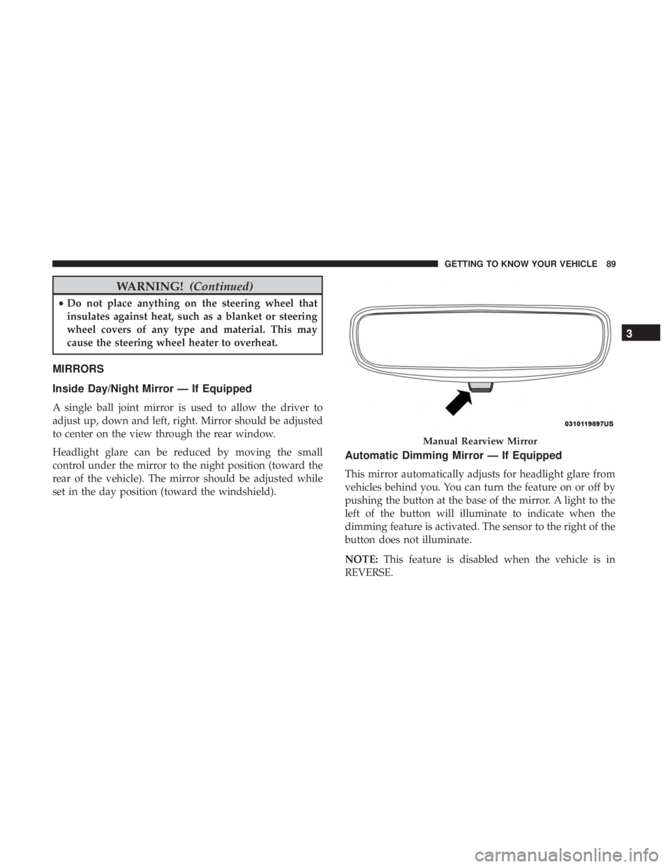
A single ball joint mirror is used to allow the driver to
adjust up, down and left, right. Mirror should be adjusted
to center on the view through the rear window.
Headlight glare can be reduced by moving the small
control under the mirror to the night position (toward the
rear of the vehicle). The mirror should be adjusted while
set in the day position (toward the windshield).
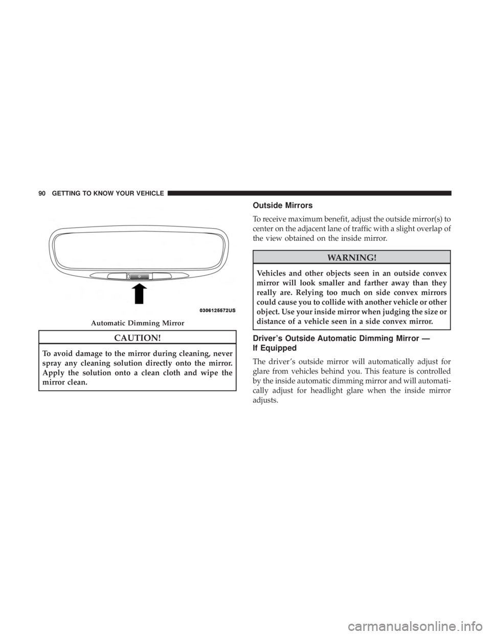
Automatic Dimming Mirror — If Equipped
This mirror automatically adjusts for headlight glare from
vehicles behind you. You can turn the feature on or off by
pushing the button at the base of the mirror. A light to the
left of the button will illuminate to indicate when the
dimming feature is activated. The sensor to the right of the
button does not illuminate.
NOTE: This feature is disabled when the vehicle is in
REVERSE.
Manual Rearview Mirror
3
GETTING TO KNOW YOUR VEHICLE 89
Page 92 of 614
CAUTION!
To avoid damage to the mirror during cleaning, never
spray any cleaning solution directly onto the mirror.
Apply the solution onto a clean cloth and wipe the
mirror clean.
Outside Mirrors
To receive maximum benefit, adjust the outside mirror(s) to
center on the adjacent lane of traffic with a slight overlap of
the view obtained on the inside mirror.
WARNING!
Vehicles and other objects seen in an outside convex
mirror will look smaller and farther away than they
really are. Relying too much on side convex mirrors
could cause you to collide with another vehicle or other
object. Use your inside mirror when judging the size or
distance of a vehicle seen in a side convex mirror.
Driver’s Outside Automatic Dimming Mirror —
If Equipped
The driver ’s outside mirror will automatically adjust for
glare from vehicles behind you. This feature is controlled
by the inside automatic dimming mirror and will automati-
cally adjust for headlight glare when the inside mirror
adjusts.
Automatic Dimming Mirror
90 GETTING TO KNOW YOUR VEHICLE
Page 99 of 614
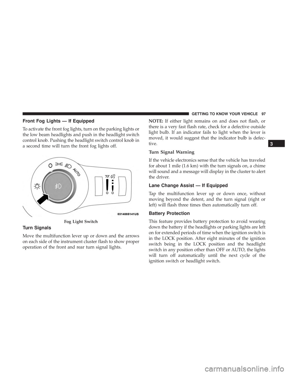
Front Fog Lights — If Equipped
To activate the front fog lights, turn on the parking lights or
the low beam headlights and push in the headlight switch
control knob. Pushing the headlight switch control knob in
a second time will turn the front fog lights off.
Turn Signals
Move the multifunction lever up or down and the arrows
on each side of the instrument cluster flash to show proper
operation of the front and rear turn signal lights.NOTE:
If either light remains on and does not flash, or
there is a very fast flash rate, check for a defective outside
light bulb. If an indicator fails to light when the lever is
moved, it would suggest that the indicator bulb is defec-
tive.
Turn Signal Warning
If the vehicle electronics sense that the vehicle has traveled
for about 1 mile (1.6 km) with the turn signals on, a chime
will sound and a message will display in the cluster to alert
the driver.
Lane Change Assist — If Equipped
Tap the multifunction lever up or down once, without
moving beyond the detent, and the turn signal (right or
left) will flash three times then automatically turn off.
Battery Protection
This feature provides battery protection to avoid wearing
down the battery if the headlights or parking lights are left
on for extended periods of time when the ignition switch is
in the LOCK position. After eight minutes of the ignition
switch being in the LOCK position and the headlight
switch in any position other than OFF or AUTO, the lights
will turn off automatically until the next cycle of the
ignition switch or headlight switch.Fog Light Switch
3
GETTING TO KNOW YOUR VEHICLE 97
Page 135 of 614
NOTE:To open the Hands-Free Liftgate requires a valid
Passive Entry key fob within 5 ft (1.5 m) of the door handle.
If a valid Passive Entry key fob is not within 5 ft (1.5 m), the
liftgate will not respond to any kicks.
CAUTION!
The Hands-Free Liftgate feature may be turned on or
off in Uconnect Settings. Refer to “Uconnect Settings”
in “Multimedia” for further information. The Hands-
Free Liftgate feature should be turned off during
Jacking, Tire Changing, and Vehicle Service.
NOTE:
• The Hands-Free Liftgate will only operate when the
transmission is in Park.
• If anything obstructs the Hands-Free liftgate while it is
opening, the liftgate will automatically reverse to the
closed position, provided it meets sufficient resistance.
• There are pinch sensors attached to the side of the
liftgate opening. Light pressure anywhere along these
strips will cause the liftgate to return to the open
position. •
If the power liftgate encounters multiple obstructions
within the same cycle, the system will automatically
stop. If this occurs, the liftgate must be operated manu-
ally.
• The power liftgate will release, but not power open, in
temperatures below �12° F (�24° C). Be sure to remove
any buildup of snow or ice from the liftgate before
opening the liftgate.
• If the liftgate is left open for an extended period of time,
the liftgate may need to be closed manually to reset
power liftgate functionality.
WARNING!
• Driving with the liftgate open can allow poisonous
exhaust gases into your vehicle. You and your pas-
sengers could be injured by these fumes. Keep the
liftgate closed when you are operating the vehicle.
• If you are required to drive with the liftgate open,
make sure that all windows are closed, and the
climate control blower switch is set at high speed. Do
not use the recirculation mode.
3
GETTING TO KNOW YOUR VEHICLE 133
Page 136 of 614
Gas props support the liftgate in the open position. How-
ever, because the gas pressure drops with temperature, it
may be necessary to assist the props when opening the
liftgate in cold weather.
NOTE:Allow the power system to open the liftgate.
Manually pushing or pulling the liftgate may activate the
liftgate obstacle detection feature and stop the power
operation or reverse its direction.
WARNING!
During power operation, personal injury or cargo
damage may occur. Ensure the liftgate travel path is
clear. Make sure the liftgate is closed and latched
before driving away.
Cargo Area Features
Cargo Area Storage
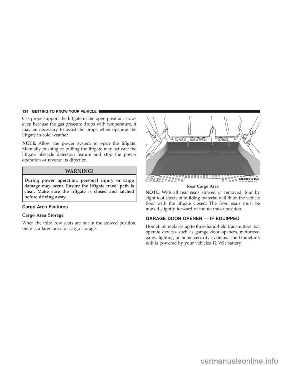
When the third row seats are not in the stowed position,
there is a large area for cargo storage. NOTE:
With all rear seats stowed or removed, four by
eight foot sheets of building material will fit on the vehicle
floor with the liftgate closed. The front seats must be
moved slightly forward of the rearmost position.GARAGE DOOR OPENER — IF EQUIPPED
HomeLink replaces up to three hand-held transmitters that
operate devices such as garage door openers, motorized
gates, lighting or home security systems. The HomeLink
unit is powered by your vehicles 12 Volt battery.
Rear Cargo Area
134 GETTING TO KNOW YOUR VEHICLE