tow bar CHRYSLER PACIFICA HYBRID 2022 Owners Manual
[x] Cancel search | Manufacturer: CHRYSLER, Model Year: 2022, Model line: PACIFICA HYBRID, Model: CHRYSLER PACIFICA HYBRID 2022Pages: 384, PDF Size: 23.92 MB
Page 5 of 384
3
UNIVERSAL GARAGE DOOR OPENER
(HOMELINK®) ....................................................... 61 Before You Begin Programming
HomeLink®.......................................................61
Erasing All The HomeLink® Channels ............61
Identifying Whether You Have A Rolling
Code Or Non-Rolling Code Device ...................62
Programming HomeLink® To A Garage
Door Opener .....................................................62
Programming HomeLink® To A
Miscellaneous Device ......................................63
Reprogramming A Single HomeLink®
Button ...............................................................63
Canadian/Gate Operator Programming .........63
Security .............................................................64
Troubleshooting Tips ........................................64
EXTERIOR LIGHTS.................................................. 65
Multifunction Lever ..........................................65
Headlight Switch...............................................65
Daytime Running Lights (DRLs) —
If Equipped........................................................66
High/Low Beam Switch....................................66
Automatic High Beam — If Equipped .............66
Flash-To-Pass ...................................................67
Automatic Headlights — If Equipped ..............67
Headlights On With Wipers —
If Equipped........................................................67
Headlight Time Delay — If Equipped ...............67
Lights-On Reminder..........................................67 Front Fog Lights — If Equipped .......................68
Turn Signals ......................................................68
Lane Change Assist — If Equipped ..................68
Battery Saver ...................................................68
INTERIOR LIGHTS ..................................................69
Interior Courtesy Lights ...................................69
WINDSHIELD WIPER AND WASHERS .................70
Windshield Wiper Operation ............................70
Rain Sensing Wipers — If Equipped ................71
Rear Wiper And Washer...................................71
CLIMATE CONTROLS .............................................72
Automatic Climate Control Descriptions
And Functions ...................................................72
Manual Climate Control Descriptions
And Functions ...................................................77
Automatic Temperature Control (ATC) —
If Equipped .......................................................82
Climate Voice Commands................................83
Operating Tips .................................................83
INTERIOR STORAGE AND EQUIPMENT ............... 84
Storage..............................................................84
Sun Screens — If Equipped..............................87
USB/AUX Control ..............................................87
Power Outlets ...................................................89
Power Inverter — If Equipped .........................91
Wireless Charging Pad — If Equipped .............91 WINDOWS .............................................................. 92
Power Windows ................................................ 92
Automatic Window Features ........................... 93
Reset Auto-Up................................................... 93
Wind Buffeting.................................................. 94
PANORAMIC SUNROOF — IF EQUIPPED ............. 94
Opening And Closing The Sunroof .................. 94
Opening And Closing The Power
Sunshade — If Equipped .................................. 95
Pinch Protect Feature ...................................... 95
Venting Sunroof................................................ 95
Ignition Off Operation....................................... 96
Sunroof Maintenance ...................................... 96
HOOD....................................................................... 96
Opening............................................................. 96
Closing ..............................................................96
LIFTGATE ................................................................. 97
To Unlock/Open The Liftgate .......................... 97
To Lock/Close The Liftgate.............................. 97
Power Liftgate — If Equipped........................... 97
Hands-Free Liftgate — If Equipped.................. 99
Cargo Area Features ................................. 100
STOW ‘N PLACE ROOF RACK —
IF EQUIPPED ........................................................ 106
Deploying The Crossbars .............................. 106
Stowing The Crossbars ................................. 108
22_RUP_OM_EN_USC_t.book Page 3
Page 42 of 384
40GETTING TO KNOW YOUR VEHICLE
Second Row Removable Quad Seat
The second row quad seats, not equipped with the
Stow ‘n Go feature, are removable for added cargo
space.
Removing Seat
1. Adjust seat to the full rearward position.
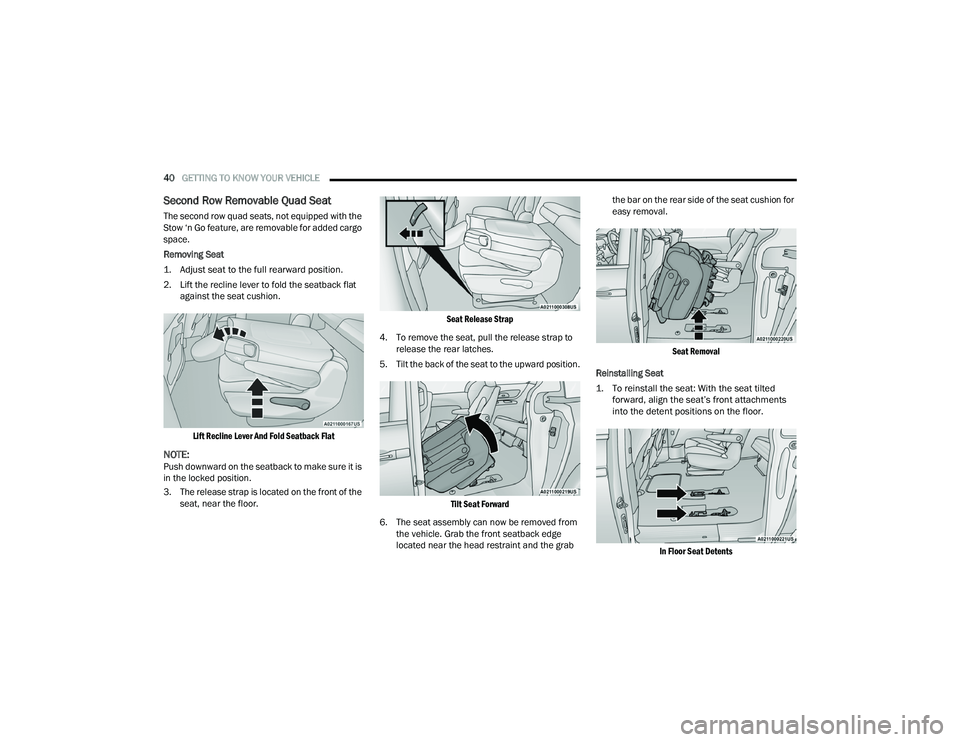
2. Lift the recline lever to fold the seatback flat
against the seat cushion.
Lift Recline Lever And Fold Seatback Flat
NOTE:Push downward on the seatback to make sure it is
in the locked position.
3. The release strap is located on the front of the seat, near the floor.
Seat Release Strap
4. To remove the seat, pull the release strap to release the rear latches.
5. Tilt the back of the seat to the upward position.
Tilt Seat Forward
6. The seat assembly can now be removed from the vehicle. Grab the front seatback edge
located near the head restraint and the grab the bar on the rear side of the seat cushion for
easy removal.
Seat Removal
Reinstalling Seat
1. To reinstall the seat: With the seat tilted forward, align the seat’s front attachments
into the detent positions on the floor.
In Floor Seat Detents
22_RUP_OM_EN_USC_t.book Page 40
Page 45 of 384
GETTING TO KNOW YOUR VEHICLE43
Using the Auto Advance ‘n Return Feature
NOTE:
The button is only functional when the power
sliding door is open and the vehicle is in PARK.
If the door is not open or the vehicle is not in
PARK when the button is pushed, the front seat
will not move and a message will be displayed in
the instrument cluster display.
If the power sliding door is closing when the
button is pushed, the front seat will not move
and a message will be displayed in the instru -
ment cluster display.
The Auto Advance ‘n Return feature will not
function if the front doors are open.
1. Push and release the Auto Advance ‘n Return button.
2. Perform the second row Stow ‘n Go seat movement Ú page 43.
3. Push and release the Auto Advance ‘n Return button a second time. The front seat cushion
and seatback will return to the original starting
location.
NOTE:
To abort seat operation while seat is in motion,
push the Auto Advance ‘n Return button, or
push the front power seat button to stop the seat movement. Pushing the Auto Advance ‘n
Return button again will return the front seat to
the original starting location.
The Auto Advance ‘n Return system includes
obstacle detection. When the system detects an
obstacle, the seat will stop, reverse direction,
and return to the previous location. A message
will be displayed in the instrument cluster indi
-
cating that an obstacle has been detected.
If the front seat is already in a location that will
allow space for Stow ‘n Go of the second row
seat, the front seat will not move and a message
will be displayed in the instrument cluster.
If calibration of the front seat is lost, the seat will
automatically recalibrate when the Auto
Advance ‘n Return button is pushed. This may
result in the seat cushion moving forward and
downward, before moving to the location that
will allow space for the second row Stow ‘n Go
seat movement.
SECOND ROW STOW 'N GO
For Manual Seats: To stow the seat in the floor, move
the front seat all the way forward using the manual
seat adjustment bar. Move the seatback all the way
forward using the recliner handle located on the
outboard side of the cushion. Move the seat height to
at least mid position using the height adjuster handle
in the outboard side of the cushion.
For Power Seats:
Push the Auto Advance ‘n Return
button located on the B-pillar trim (if equipped)
Ú page 42.
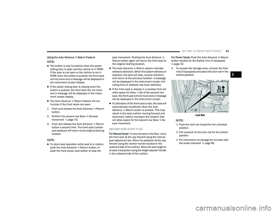
1. To access the storage area, remove the floor mat (if equipped) and place the lock rod in the
locked position.
Lock Rod
NOTE:
Push the lock rod inward for the unlocked
position.
Pull outward on the lock rod for the locked
position.
For information on storage bin function with
the seats rearward Ú page 85.
2
22_RUP_OM_EN_USC_t.book Page 43
Page 47 of 384
GETTING TO KNOW YOUR VEHICLE45
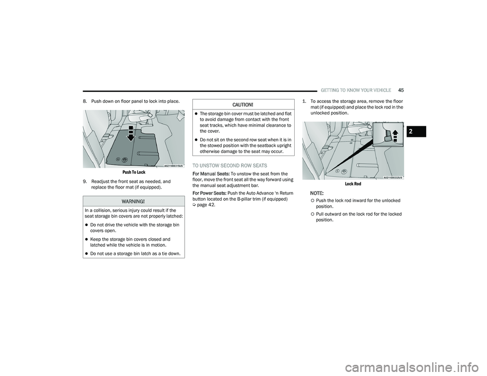
8. Push down on floor panel to lock into place.
Push To Lock
9. Readjust the front seat as needed, and replace the floor mat (if equipped).
TO UNSTOW SECOND ROW SEATS
For Manual Seats: To unstow the seat from the
floor, move the front seat all the way forward using
the manual seat adjustment bar.
For Power Seats: Push the Auto Advance ‘n Return
button located on the B-pillar trim (if equipped)
Ú page 42.
1. To access the storage area, remove the floor
mat (if equipped) and place the lock rod in the
unlocked position.
Lock Rod
NOTE:
Push the lock rod inward for the unlocked
position.
Pull outward on the lock rod for the locked
position.
WARNING!
In a collision, serious injury could result if the
seat storage bin covers are not properly latched:
Do not drive the vehicle with the storage bin
covers open.
Keep the storage bin covers closed and
latched while the vehicle is in motion.
Do not use a storage bin latch as a tie down.
CAUTION!
The storage bin cover must be latched and flat
to avoid damage from contact with the front
seat tracks, which have minimal clearance to
the cover.
Do not sit on the second row seat when it is in
the stowed position with the seatback upright
otherwise damage to the seat may occur.
2
22_RUP_OM_EN_USC_t.book Page 45
Page 68 of 384
66GETTING TO KNOW YOUR VEHICLE
From the O (off) position, rotate the headlight switch
clockwise to the first detent for parking light and
instrument panel light operation. Rotate the
headlight switch to the second detent for headlight,
parking light and instrument panel operation.
NOTE:For vehicles sold in Canada, rotate the headlight
switch clockwise from the parking light and
instrument panel light position to the first detent to
turn on the headlights also. Rotate to the second
detent, AUTO position, to turn on automatic head -
lights, parking lights, and instrument panel lights.
DAYTIME RUNNING LIGHTS (DRLS) —
I
F EQUIPPED
The headlights or LED light bars on your vehicle will
illuminate when the engine is started. This
provides a constant lights on condition until the
ignition is placed in the OFF position. If the parking
brake is applied, the Daytime Running Lights
(DRLs) will turn off.
NOTE:
For vehicles sold in Canada, the Daytime
Running Lights will automatically deactivate
when the front fog lights are turned on.
If allowed by law in the country in which the
vehicle was purchased, the Daytime Running
Lights can be turned on and off using the Ucon -
nect system Ú page 188.
On some vehicles, the Daytime Running Lights
may deactivate, or reduce intensity, on one side
of the vehicle (when a turn signal is activated on
that side), or on both sides of the vehicle (when
the hazard warning lights are activated).
HIGH/LOW BEAM SWITCH
Push the multifunction lever toward the instrument
panel to switch the headlights to high beams.
Pulling the multifunction lever back will turn the
low beams on.
AUTOMATIC HIGH BEAM — IF EQUIPPED
The Automatic High Beam system provides
increased forward lighting at night by automatically
controlling the high beams through the use of a
camera mounted on the windshield. This camera
detects vehicle specific light and automatically
switches from high beams to low beams until the
approaching vehicle is out of view.
NOTE:Broken, muddy, or obstructed headlights and tail -
lights of vehicles in the field of view will cause
headlights to remain on longer (closer to the
vehicle). Also, dirt, film and other obstructions on
the windshield or camera lens will cause the
system to function improperly.
To Activate
1. Select “Auto Dim High Beams” through the Uconnect system to enable the feature
Ú
page 188.
2. Rotate the headlight switch clockwise to the AUTO position.
3. Push the multifunction lever away from you to switch the headlights to the high beam
position. Refer to “Multifunction Lever” in this
section for further information.
NOTE:This system will not activate until the vehicle is at,
or above 16 mph (25 km/h).
To Deactivate
Perform either of the following steps to deactivate
the Automatic High Beam system.
1. Deselect “Auto Dim High Beams” through the Uconnect system
Ú
page 188.
2. Pull the multifunction lever toward you to switch the headlights from the high beam to
the low beam position.
3. Rotate the headlight switch counterclockwise from the AUTO to the on position.
NOTE:Once active, the Automatic High Beam system will
stop functioning below 12 mph (20 km/h).
22_RUP_OM_EN_USC_t.book Page 66
Page 75 of 384
GETTING TO KNOW YOUR VEHICLE73
AUTO Button
Set your desired temperature and press
the AUTO button on the touchscreen, or
push the button on the faceplate. AUTO
will achieve and maintain your desired
temperature by automatically adjusting the blower
speed and air distribution. Air Conditioning (A/C)
may be active during AUTO operation to improve
performance. AUTO mode is highly recommended
for efficiency. You can turn AUTO on in one of two
ways:
Press and release this button on the touch -
screen
Push the button on the faceplate
Toggling this function will cause the system to
switch between manual mode and automatic
mode Ú page 82.
Front Defrost Button
Press and release the Front Defrost
button on the touchscreen, or push the
button on the faceplate to change the
current airflow setting to Defrost mode.
The indicator illuminates when this feature is on.
Air comes from the windshield and side window
demist outlets. When the defrost button is
selected, the blower level may increase. Use
Defrost mode with maximum temperature settings
for best windshield and side window defrosting
and defogging. Performing this function will cause the Automatic Temperature Control (ATC) to switch
into manual mode. If the Front Defrost mode is
turned off the climate system will return to the
previous setting.
Rear Defrost Button
Press and release the Rear Defrost
Control button on the touchscreen or
push and release the button on the
faceplate to turn on the rear window
defroster and the heated outside mirrors (if
equipped). An indicator will illuminate when the
rear window defroster is on. The rear window
defroster automatically turns off after 15 minutes.
Front Temperature Control
These buttons provide the driver and passenger
with independent temperature control.
Push the red button on the faceplate or
touchscreen or press and slide the
temperature bar towards the red arrow
button on the touchscreen for warmer
temperature settings.
Push the blue button on the faceplate or
touchscreen or press and slide the
temperature bar towards the blue arrow
button on the touchscreen for cooler
temperature settings.
NOTE:The temperature can also be adjusted by pressing
the Temperature readout on the top left and right
corners of the status bar.
SYNC Button
Press the SYNC button on the
touchscreen to toggle the SYNC feature
on/off. The SYNC indicator is illuminated
when this feature is enabled. SYNC is
used to synchronize the front and rear passenger
temperature settings with the driver temperature
setting. Changing the front or rear passenger
temperature setting while in SYNC will
automatically exit this feature.
NOTE:
The SYNC setting is only available on the touchscreen.
CAUTION!
Failure to follow these cautions can cause
damage to the heating elements:
Use care when washing the inside of the rear
window. Do not use abrasive window cleaners
on the interior surface of the window. Use a
soft cloth and a mild washing solution, wiping
parallel to the heating elements. Labels can
be peeled off after soaking with warm water.
Do not use scrapers, sharp instruments, or
abrasive window cleaners on the interior
surface of the window.
Keep all objects a safe distance from the
window.
2
22_RUP_OM_EN_USC_t.book Page 73
Page 80 of 384
78GETTING TO KNOW YOUR VEHICLE
Recirculation Button
Press and release this button to change
the system between recirculation mode
and outside air mode. The Recirculation
indicator and the A/C indicator illuminate
when the Recirculation button is pressed.
Recirculation can be used when outside conditions
such as smoke, odors, dust, or high humidity are
present. Recirculation can be used in all modes
except for Defrost. Recirculation may be
unavailable (button on the touchscreen greyed
out) if conditions exist that could create fogging on
the inside of the windshield. The A/C (Air
Conditioning) can be deselected manually without
disturbing the mode control selection. Continuous
use of the Recirculation mode may make the
inside air stuffy and window fogging may occur.
Extended use of this mode is not recommended.
On systems with Manual Climate Controls, the
Recirculation mode (if equipped) is not allowed in
Defrost mode to improve window clearing
operation. Recirculation is disabled automatically
if this mode is selected. Attempting to use
Recirculation while in this mode causes the LED on
the control button to blink and then turn off.
Front Defrost Button
Press and release the Front Defrost
button to change the current airflow
setting to Defrost mode. The indicator
illuminates when this feature is on.
Air comes from the windshield and side window
demist outlets. When the defrost button is
selected, the blower level may increase. Use
Defrost mode with maximum temperature settings
for best windshield and side window defrosting
and defogging. Performing this function will cause
the Automatic Temperature Control (ATC) to switch
into manual mode. If the Front Defrost mode is
turned off the climate system will return the
previous setting.
Rear Defrost Button
Push and release the Rear Defrost
Control button to turn on the rear window
defroster and the heated outside mirrors
(if equipped). An indicator will illuminate
when the rear window defroster is on. The rear
window defroster automatically turns off after
15 minutes.Front Temperature Control
These buttons provide the driver and passenger
with independent temperature control.
Push the red button on the faceplate or
touchscreen or press and slide the
temperature bar towards the red arrow
button on the touchscreen for warmer
temperature settings.
CAUTION!
Failure to follow these cautions can cause
damage to the heating elements:
Use care when washing the inside of the rear
window. Do not use abrasive window cleaners
on the interior surface of the window. Use a
soft cloth and a mild washing solution, wiping
parallel to the heating elements. Labels can
be peeled off after soaking with warm water.
Do not use scrapers, sharp instruments, or
abrasive window cleaners on the interior
surface of the window.
Keep all objects a safe distance from the
window.
22_RUP_OM_EN_USC_t.book Page 78
Page 81 of 384
GETTING TO KNOW YOUR VEHICLE79
Push the blue button on the faceplate or
touchscreen or press and slide the
temperature bar towards the blue arrow
button on the touchscreen for cooler
temperature settings.
SYNC Button
Press the SYNC button on the
touchscreen to toggle the Sync feature
on/off. The SYNC indicator is illuminated
when this feature is enabled. SYNC is
used to synchronize the front and rear passenger
temperature settings with the driver temperature
setting. Changing the front or rear passenger
temperature setting while in SYNC will
automatically exit this feature. Pressing SYNC on
the touchscreen while in the Front Climate screen
synchronizes the driver and passenger
temperatures only. In order to SYNC rear
temperature to driver temperature, the
touchscreen must be on the Rear Climate screen.
NOTE:The SYNC setting is only available on the touch -
screen.
Blower Control
Blower Control is used to regulate the
amount of air forced through the Climate
Control system. There are seven blower
speeds available. The speeds can be
selected using either the blower control knob on
the faceplate or the buttons on the touchscreen.
Faceplate: The blower speed increases as you
turn the blower control knob clockwise from the
lowest blower setting. The blower speed
decreases as you turn the blower control knob
counterclockwise.
Touchscreen: Use the small blower icon to
reduce the blower setting and the large blower
icon to increase the blower setting. Blower
speed can also be selected by pressing the
blower bar area between the icons.
Mode Control
The airflow distribution mode can be
adjusted so air comes from the
instrument panel outlets, floor outlets,
defrost outlets and demist outlets.
Faceplate: Push the button in the center of the
knob to change the airflow distribution mode.
Touchscreen: Select Mode by pressing one of the
Mode Buttons on the touchscreen.
Panel Mode
Air comes from the outlets in the
instrument panel. Each of these outlets
can be individually adjusted to direct the
flow of air. The air vanes of the center
outlets and outboard outlets can be moved up and
down or side to side to regulate airflow direction.
There is a shut-off wheel located below the air
vanes to shut off or adjust the amount of airflow
from these outlets.
Bi-Level Mode
Air comes from the instrument panel
outlets and floor outlets. A slight amount
of air is directed through the defrost and
side window demister outlets.
NOTE:Bi-Level mode is designed under comfort condi -
tions to provide cooler air out of the panel outlets
and warmer air from the floor outlets.
Floor Mode
Air comes from the floor outlets. A slight
amount of air is directed through the
defrost and side window demister
outlets.
2
22_RUP_OM_EN_USC_t.book Page 79
Page 108 of 384
106GETTING TO KNOW YOUR VEHICLE
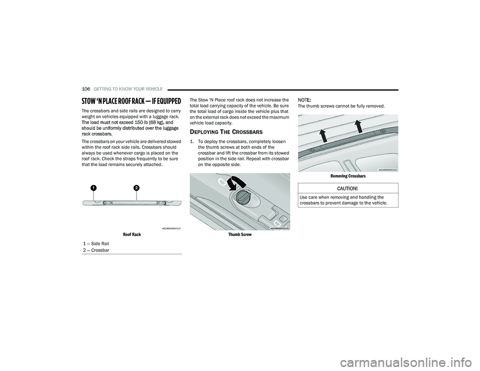
STOW ‘N PLACE ROOF RACK — IF EQUIPPED
The crossbars and side rails are designed to carry
weight on vehicles equipped with a luggage rack.
The load must not exceed 150 lb (68 kg), and
should be uniformly distributed over the luggage
rack crossbars.
The crossbars on your vehicle are delivered stowed
within the roof rack side rails. Crossbars should
always be used whenever cargo is placed on the
roof rack. Check the straps frequently to be sure
that the load remains securely attached.
Roof Rack
The Stow ‘N Place roof rack does not increase the
total load carrying capacity of the vehicle. Be sure
the total load of cargo inside the vehicle plus that
on the external rack does not exceed the maximum
vehicle load capacity.
DEPLOYING THE CROSSBARS
1. To deploy the crossbars, completely loosen
the thumb screws at both ends of the
crossbar and lift the crossbar from its stowed
position in the side rail. Repeat with crossbar
on the opposite side.
Thumb Screw
NOTE:The thumb screws cannot be fully removed.
Removing Crossbars
1 — Side Rail
2 — Crossbar
CAUTION!
Use care when removing and handling the
crossbars to prevent damage to the vehicle.
22_RUP_OM_EN_USC_t.book Page 106
Page 110 of 384

108GETTING TO KNOW YOUR VEHICLE
STOWING THE CROSSBARS
1. Starting with one crossbar, completely loosen
the thumb screws at both ends. Lift the
crossbar away from the matching letter to
remove it from the deployed position.
Repeat with the other crossbar.
2. Starting with the one crossbar, bend up the pivot supports at each end.
Crossbar Pivot
3. Then, position the crossbar along the correct
side rail. Make sure the letters on the crossbar
align with the matching letters on the side rail.
Stowing Crossbars
4. The crossbar will nest fully within the side rail.
Crossbar To Side Rail
5. Once the driver’s side crossbar is in place,
tighten the thumb screws completely.
Tightening Crossbar
6. Repeat the procedure to stow the second crossbar on the opposite side.
Stowed Crossbars
CAUTION!
Use care when removing and handling the
crossbars to prevent damage to the vehicle.
22_RUP_OM_EN_USC_t.book Page 108