wheel torque CHRYSLER PACIFICA HYBRID 2022 Owners Manual
[x] Cancel search | Manufacturer: CHRYSLER, Model Year: 2022, Model line: PACIFICA HYBRID, Model: CHRYSLER PACIFICA HYBRID 2022Pages: 384, PDF Size: 23.92 MB
Page 9 of 384
7
JUMP STARTING................................................... 300 Preparations For Jump Start......................... 301Jump Starting Procedure .............................. 301
REFUELING IN EMERGENCY –
IF EQUIPPED ......................................................... 302
IF YOUR ENGINE OVERHEATS ............................ 303
MANUAL PARK RELEASE .................................. 304
FREEING A STUCK VEHICLE .............................. 305
TOWING A DISABLED VEHICLE .......................... 306
All Wheel Drive (AWD) Models ...................... 308
ENHANCED ACCIDENT RESPONSE SYSTEM
(EARS) .................................................................. 308
EVENT DATA RECORDER (EDR) ......................... 308
SERVICING AND MAINTENANCE
SCHEDULED SERVICING ..................................... 309
Maintenance Plan ......................................... 310
ENGINE COMPARTMENT .................................... 313
3.6L Engine.................................................... 313
Checking Oil Level ......................................... 314
Adding Washer Fluid .................................... 314
Maintenance-Free Battery ........................... 314
Pressure Washing ......................................... 315 VEHICLE MAINTENANCE..................................... 315
Engine Oil ...................................................... 315
Engine Oil Filter ............................................. 316Engine Air Cleaner Filter ............................... 316
Accessory Drive Belt Inspection ................... 317Air Conditioner Maintenance........................ 317
Body Lubrication ........................................... 320Windshield Wiper Blades.............................. 320Exhaust System ............................................ 323
Cooling System .............................................. 324
Brake System ............................................... 327
Automatic Transmission .............................. 328Fuses.............................................................. 329
Bulb Replacement......................................... 337
TIRES ................................................................... 339
Tire Safety Information ................................. 339
Tires — General Information ......................... 346
Tire Types....................................................... 350
Spare Tires — If Equipped ............................ 350
Wheel And Wheel Trim Care ........................ 352
Snow Traction Devices ................................. 353
Tire Rotation Recommendations ................. 355 DEPARTMENT OF TRANSPORTATION
UNIFORM TIRE QUALITY GRADES .................... 355
Treadwear...................................................... 356
Traction Grades ............................................. 356Temperature Grades..................................... 356
STORING THE VEHICLE ....................................... 357
BODYWORK .......................................................... 357
Protection From Atmospheric Agents ......... 357
Body And Underbody Maintenance ............. 357
Preserving The Bodywork ............................. 357
INTERIORS ........................................................... 358
Seats And Fabric Parts ................................. 358
Plastic And Coated Parts .............................. 359
Leather Surfaces........................................... 359
Glass Surfaces ............................................. 359TECHNICAL SPECIFICATIONS
VEHICLE IDENTIFICATION NUMBER
(VIN) ....................................................................... 360
BRAKE SYSTEM ................................................... 360
WHEEL AND TIRE TORQUE
SPECIFICATIONS .................................................. 360Torque Specifications ................................... 360
22_RUP_OM_EN_USC_t.book Page 7
Page 145 of 384
STARTING AND OPERATING143
ALL-WHEEL DRIVE (AWD) — IF EQUIPPED
This feature provides on-demand All-Wheel Drive
(AWD). The system is automatic with no driver
inputs or additional driving skills required. Under
normal driving conditions, the front wheels provide
most of the traction. If the front wheels begin to
lose traction, power is shifted automatically to the
rear wheels. The greater the front wheel traction
loss, the greater the power transfer to the rear
wheels.
Additionally, on dry pavement under heavy throttle
input (where one may have no wheel spin), torque
will be sent to the rear in a preemptive effort to
improve vehicle launch and performance
characteristics.
ACTIVE NOISE CANCELLATION
Your vehicle is equipped with an Active Noise
Cancellation system. This system is designed to
address exhaust and engine noise. The system
relies on four microphones embedded in the
headliner, which monitor exhaust and engine noise, and assists an onboard frequency
generator, which creates counteracting sound
waves in the audio system’s speakers. This helps
keep the vehicle quiet at idle and during drive.
POWER STEERING
The electric power steering system will provide
increased vehicle response and ease of
maneuverability. The power steering system
adapts to different driving conditions.
If the Steering icon is displayed and the “POWER
STEERING SYSTEM OVER TEMP” message is
displayed on the instrument cluster screen, this
indicates an over temperature condition in the
power steering system. Once driving conditions are
safe, pull over and let the vehicle idle for a few
moments until the icon and message turn off
Ú
page 121.
If the “SERVICE POWER STEERING" or
"POWER STEERING ASSIST OFF -
SERVICE SYSTEM” message and a
steering wheel icon are displayed on the
instrument cluster screen, it indicates that the vehicle needs to be taken to an authorized dealer
for service. It is likely the vehicle has lost power
steering assistance Ú
page 121.
NOTE:
Even if the power steering assistance is no
longer operational, it is still possible to steer
the vehicle. Under these conditions there will be
a substantial increase in steering effort,
especially at low speeds and during parking
maneuvers.
The power steering system is fully electric; it
requires no power steering fluid.
If the condition persists, see an authorized
dealer for service.
STOP/START SYSTEM — IF EQUIPPED
The Stop/Start function is developed to reduce
fuel consumption. The system will stop the engine
automatically during a vehicle stop if the required
conditions are met. Releasing the brake pedal,
pressing the accelerator pedal or shifting out of
DRIVE (D) will automatically re-start the engine.
This vehicle has been upgraded with a heavy-duty
starter, enhanced battery, and other upgraded
engine parts to handle the additional engine starts.CAUTION!
All wheels must have the same size and type
tires. Unequal tire sizes must not be used.
Unequal tire size may cause premature wear of
the driveline components.
WARNING!
Continued operation with reduced assist could
pose a safety risk to yourself and others. Service
should be obtained as soon as possible.
4
22_RUP_OM_EN_USC_t.book Page 143
Page 168 of 384

166STARTING AND OPERATING
LANESENSE — IF EQUIPPED
LANESENSE OPERATION
The LaneSense system is operational at speeds
above 37 mph (60 km/h) and below 112 mph
(180 km/h). It uses a forward-looking camera to
detect lane markings and measure vehicle
position within the lane boundaries.
When both lane markings are detected and the
driver drifts out of the lane (no turn signal applied),
the LaneSense system provides a haptic warning
in the form of torque applied to the steering wheel,
as well as a visual warning in the instrument
cluster display, to prompt the driver to remain
within the lane boundaries.
The driver may manually override the haptic
warning by applying force to the steering wheel at
any time.
When only a single lane marking is detected and
the driver unintentionally drifts across that lane
marking (no turn signal applied), the LaneSense
system provides a visual warning through the
instrument cluster display to prompt the driver to
remain within the lane. When only a single lane
marking is detected, a haptic or a torque warning
will not be provided.
NOTE:When operating conditions have been met, the
LaneSense system will monitor if the driver’s
hands are on the steering wheel and provide an
audible and visual warning to the driver when the
driver’s hands are not detected on the steering
wheel. The system will cancel if the driver does not
return their hands to the wheel.
TURNING LANESENSE ON OR OFF
The LaneSense button is located on the
switch panel below the Uconnect display.
To turn the LaneSense system on, push the
LaneSense button (LED turns off). A “LaneSense
On” message is shown in the instrument cluster
display.
To turn the LaneSense system off, push the
LaneSense button again (LED turns on).
NOTE:The LaneSense system will retain the last system
state on or off from the last ignition cycle when the
ignition is changed to the ON/RUN position.
LANESENSE WARNING MESSAGE
The LaneSense system will indicate the current
lane drift condition through the instrument cluster
display.
When the LaneSense system is on, the lane lines
are gray when both of the lane boundaries have
not been detected and the LaneSense telltale
is solid white.
System ON (Gray Lines) With White Telltale
22_RUP_OM_EN_USC_t.book Page 166
Page 169 of 384

STARTING AND OPERATING167
Left Lane Departure — Only Left Lane Detected
When the LaneSense system is on, the Lane -
Sense Telltale is solid white only when the
left lane marking has been detected and the
system is ready to provide visual warnings in the
instrument cluster display if an unintentional
lane departure occurs on the left side.
When the LaneSense system senses the lane
has been approached and is in a lane departure
situation, the visual warning in the instrument
cluster display will show the left inside lane line
flashing yellow (on/off), while the outside lane
line on the left of the display will remain solid
yellow. The LaneSense telltale changes from
solid white to flashing yellow.
Lane Approached With Flashing Yellow Line/ Flashing Yellow Telltale
NOTE:The LaneSense system operates with similar
behavior for a right lane departure when only the
right lane marking has been detected.
Left Lane Departure — Both Lane Lines Detected
When the LaneSense system is on, the lane
lines turn from gray to white. The LaneSense
telltale is solid green when both lane mark -
ings have been detected and the system is
“armed” to provide visual warnings in the instru -
ment cluster display and a torque warning in the
steering wheel if an unintentional lane depar -
ture occurs.
Lanes Sensed (White Lines) With Green Telltale
When the LaneSense system senses a lane drift
situation, the left inside and outside lane lines
turn solid yellow. The LaneSense telltale
changes from solid green to solid yellow. At this
time torque is applied to the steering wheel in
the opposite direction of the lane boundary.
For example: If approaching the left side of the
lane the steering wheel will turn to the right.
Lane Drift With Solid Yellow Line/Solid Yellow Telltale
4
22_RUP_OM_EN_USC_t.book Page 167
Page 170 of 384
168STARTING AND OPERATING
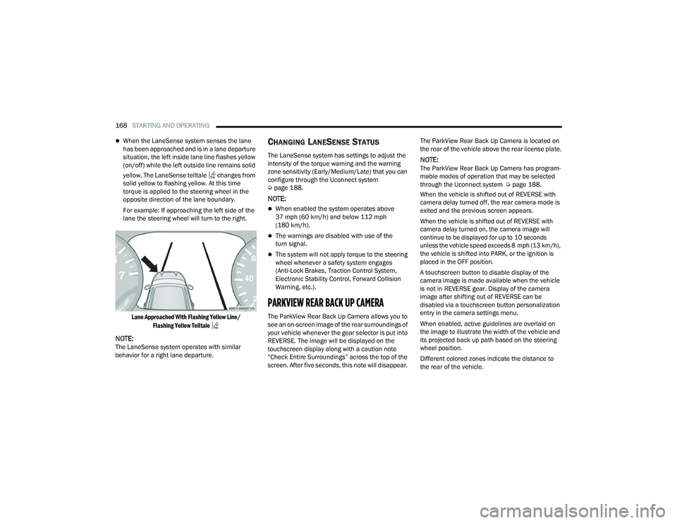
When the LaneSense system senses the lane
has been approached and is in a lane departure
situation, the left inside lane line flashes yellow
(on/off) while the left outside line remains solid
yellow. The LaneSense telltale changes from
solid yellow to flashing yellow. At this time
torque is applied to the steering wheel in the
opposite direction of the lane boundary.
For example: If approaching the left side of the
lane the steering wheel will turn to the right.
Lane Approached With Flashing Yellow Line/ Flashing Yellow Telltale
NOTE:The LaneSense system operates with similar
behavior for a right lane departure.
CHANGING LANESENSE STATUS
The LaneSense system has settings to adjust the
intensity of the torque warning and the warning
zone sensitivity (Early/Medium/Late) that you can
configure through the Uconnect system
Úpage 188.
NOTE:
When enabled the system operates above
37 mph (60 km/h) and below 112 mph
(180 km/h).
The warnings are disabled with use of the
turn signal.
The system will not apply torque to the steering
wheel whenever a safety system engages
(Anti-Lock Brakes, Traction Control System,
Electronic Stability Control, Forward Collision
Warning, etc.).
PARKVIEW REAR BACK UP CAMERA
The ParkView Rear Back Up Camera allows you to
see an on-screen image of the rear surroundings of
your vehicle whenever the gear selector is put into
REVERSE. The image will be displayed on the
touchscreen display along with a caution note
“Check Entire Surroundings” across the top of the
screen. After five seconds, this note will disappear. The ParkView Rear Back Up Camera is located on
the rear of the vehicle above the rear license plate.
NOTE:The ParkView Rear Back Up Camera has program
-
mable modes of operation that may be selected
through the Uconnect system Ú page 188.
When the vehicle is shifted out of REVERSE with
camera delay turned off, the rear camera mode is
exited and the previous screen appears.
When the vehicle is shifted out of REVERSE with
camera delay turned on, the camera image will
continue to be displayed for up to 10 seconds
unless the vehicle speed exceeds 8 mph (13 km/h),
the vehicle is shifted into PARK, or the ignition is
placed in the OFF position.
A touchscreen button to disable display of the
camera image is made available when the vehicle
is not in REVERSE gear. Display of the camera
image after shifting out of REVERSE can be
disabled via a touchscreen button personalization
entry in the camera settings menu.
When enabled, active guidelines are overlaid on
the image to illustrate the width of the vehicle and
its projected back up path based on the steering
wheel position.
Different colored zones indicate the distance to
the rear of the vehicle.
22_RUP_OM_EN_USC_t.book Page 168
Page 227 of 384
SAFETY225
Dynamic Steering Torque (DST)
DST is a feature of the ESC and Electric Power
Steering (EPS) modules that provides torque at the
steering wheel for certain driving conditions in
which the ESC module is detecting vehicle
instability. The torque that the steering wheel
receives is only meant to help the driver
realize optimal steering behavior in order to
reach/maintain vehicle stability. The only
notification the driver receives that the feature is
active, is the torque applied to the steering wheel.
NOTE:The DST feature is only meant to help the driver
realize the correct course of action through small
torques on the steering wheel, which means the
effectiveness of the DST feature is highly
dependent on the driver’s sensitivity and overall
reaction to the applied torque. It is very important
to realize that this feature will not steer the vehicle,
meaning the driver is still responsible for steering
the vehicle.
Electronic Brake Force Distribution (EBD)
The EBD function manages the distribution of the
braking torque between the front and rear axles by
limiting braking pressure to the rear axle. This is
done to prevent overslip of the rear wheels to avoid
vehicle instability, and to prevent the rear axle from
entering the Anti-Lock Brake System (ABS) before
the front axle.
Electronic Roll Mitigation (ERM)
ERM anticipates the potential for wheel lift by
monitoring the driver’s steering wheel input and
the speed of the vehicle. When ERM determines
that the rate of change of the steering wheel angle
and vehicle’s speed are sufficient to potentially
cause wheel lift, it then applies the appropriate
brake and may also reduce engine power to lessen
the chance that wheel lift will occur. ERM can only
reduce the chance of wheel lift occurring during
severe or evasive driving maneuvers; it cannot
prevent wheel lift due to other factors, such as
road conditions, leaving the roadway, striking
objects or other vehicles.
Electronic Stability Control (ESC)
ESC enhances directional control and stability of
the vehicle under various driving conditions. ESC
corrects for oversteering or understeering of the
vehicle by applying the brake of the appropriate
wheel(s) to assist in counteracting the above
conditions. Engine power may also be reduced to
help the vehicle maintain the desired path.
Oversteer — when the vehicle is turning more
than appropriate for the steering wheel position.
Understeer — when the vehicle is turning less
than appropriate for the steering wheel position.
ESC uses sensors in the vehicle to determine the
vehicle path intended by the driver and compares
it to the actual path of the vehicle. When the actual
path does not match the intended path, ESC
applies the brake of the appropriate wheel to
assist in counteracting the oversteer or understeer
condition.
WARNING!
Many factors, such as vehicle loading, road
conditions and driving conditions, influence the
chance that wheel lift or rollover may occur. ERM
cannot prevent all wheel lift or rollovers,
especially those that involve leaving the roadway
or striking objects or other vehicles. The
capabilities of an ERM-equipped vehicle must
never be exploited in a reckless or dangerous
manner which could jeopardize the user's safety
or the safety of others.
6
22_RUP_OM_EN_USC_t.book Page 225
Page 231 of 384

SAFETY229
If one wheel on a driven axle is spinning faster than
the other, the system will apply the brake of the
spinning wheel. This will allow more vehicle torque
to be applied to the wheel that is not spinning. BLD
may remain enabled even if TCS and the Electronic
Stability Control (ESC) are in reduced modes.
Trailer Sway Control (TSC)
TSC uses sensors in the vehicle to recognize an
excessively swaying trailer and will take the
appropriate actions to attempt to stop the sway.
Note that TSC cannot stop all trailers from swaying.
Always use caution when towing a trailer and follow
the trailer tongue weight recommendations
Ú page 174.
When TSC is functioning, the ESC Activation/
Malfunction Indicator Light will flash, the engine
power may be reduced and you may feel the
brakes being applied to individual wheels to
attempt to stop the trailer from swaying. TSC is
disabled when the ESC system is in the “Partial
Off” mode.
AUXILIARY DRIVING SYSTEMS
BLIND SPOT MONITORING (BS M) —
I
F EQUIPPED
The BSM system uses two radar sensors, located
inside the rear fascia/bumper, to detect highway
licensable vehicles (automobiles, trucks,
motorcycles, etc.) that enter the blind spot zones
from the rear/front/side of the vehicle.
Rear Detection Zones
When the vehicle is started, the BSM Warning Light
will momentarily illuminate in both outside
rearview mirrors to let the driver know that the
system is operational. The BSM system sensors
operate when the vehicle is in any forward gear
and enters standby mode when the vehicle is in
PARK (P). The BSM detection zone covers approximately one
lane width on both sides of the vehicle 12 ft
(3.7 m). The zone length starts at the outside
rearview mirror and extends approximately 10 ft
(3 m) beyond the rear fascia/bumper of the
vehicle. The BSM system monitors the detection
zones on both sides of the vehicle when the vehicle
speed reaches approximately 6 mph (10 km/h) or
higher and will alert the driver of vehicles in these
areas.
NOTE:
The BSM system DOES NOT alert the driver
about rapidly approaching vehicles that are
outside the detection zones.
The BSM system detection zone DOES NOT
change if your vehicle is towing a trailer. There
-
fore, visually verify the adjacent lane is clear for
both your vehicle and trailer before making a
lane change. If the trailer or other object
(i.e., bicycle, sports equipment) extends beyond
the side of your vehicle, this may result in false
detections. The BSM Warning Light may even
remain illuminated the entire time the vehicle is
in a forward gear.
WARNING!
If TSC activates while driving, slow the vehicle
down, stop at the nearest safe location, and
adjust the trailer load to eliminate trailer sway.
6
22_RUP_OM_EN_USC_t.book Page 229
Page 293 of 384
IN CASE OF EMERGENCY291
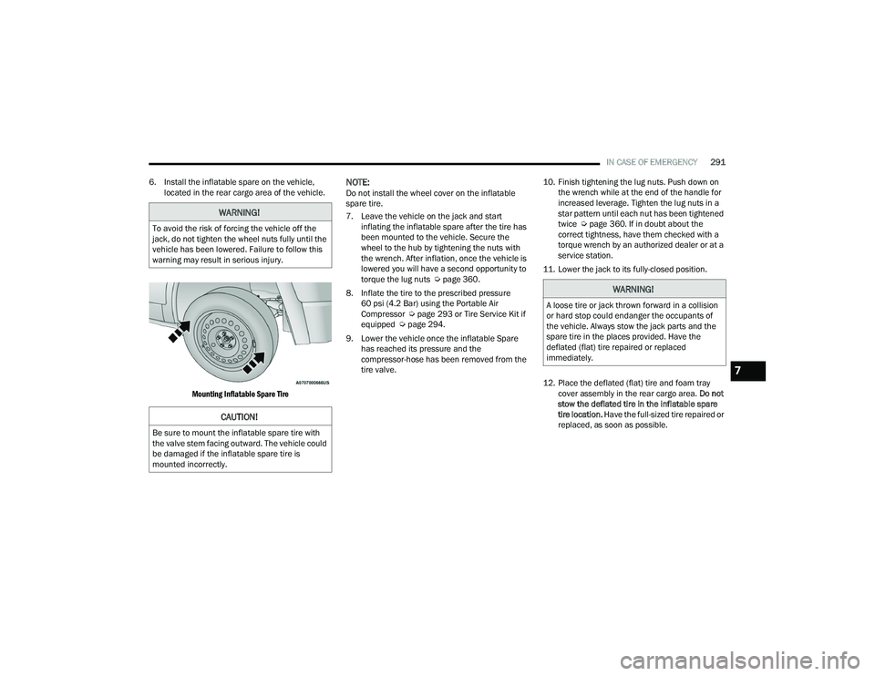
6. Install the inflatable spare on the vehicle, located in the rear cargo area of the vehicle.
Mounting Inflatable Spare Tire
NOTE:Do not install the wheel cover on the inflatable
spare tire.
7. Leave the vehicle on the jack and start inflating the inflatable spare after the tire has
been mounted to the vehicle. Secure the
wheel to the hub by tightening the nuts with
the wrench. After inflation, once the vehicle is
lowered you will have a second opportunity to
torque the lug nuts Ú page 360.
8. Inflate the tire to the prescribed pressure 60 psi (4.2 Bar) using the Portable Air
Compressor Ú page 293 or Tire Service Kit if
equipped Ú page 294.
9. Lower the vehicle once the inflatable Spare has reached its pressure and the
compressor-hose has been removed from the
tire valve. 10. Finish tightening the lug nuts. Push down on
the wrench while at the end of the handle for
increased leverage. Tighten the lug nuts in a
star pattern until each nut has been tightened
twice Ú page 360. If in doubt about the
correct tightness, have them checked with a
torque wrench by an authorized dealer or at a
service station.
11. Lower the jack to its fully-closed position.
12. Place the deflated (flat) tire and foam tray cover assembly in the rear cargo area. Do not
stow the deflated tire in the inflatable spare
tire location. Have the full-sized tire repaired or
replaced, as soon as possible.
WARNING!
To avoid the risk of forcing the vehicle off the
jack, do not tighten the wheel nuts fully until the
vehicle has been lowered. Failure to follow this
warning may result in serious injury.
CAUTION!
Be sure to mount the inflatable spare tire with
the valve stem facing outward. The vehicle could
be damaged if the inflatable spare tire is
mounted incorrectly.
WARNING!
A loose tire or jack thrown forward in a collision
or hard stop could endanger the occupants of
the vehicle. Always stow the jack parts and the
spare tire in the places provided. Have the
deflated (flat) tire repaired or replaced
immediately.
7
22_RUP_OM_EN_USC_t.book Page 291
Page 295 of 384
IN CASE OF EMERGENCY293
5. Lower the vehicle to the ground by turning the jack handle counterclockwise.
6. Finish tightening the lug nuts. Push down on the wrench while at the end of the handle for
increased leverage. Tighten the lug nuts in a
star pattern until each nut has been tightened
twice Ú page 360. If in doubt about the
correct tightness, have them checked with a
torque wrench by an authorized dealer or at a
service station.
7. After 25 miles (40 km) check the lug nut torque with a torque wrench to ensure that all
lug nuts are properly seated against the wheel.
PORTABLE AIR COMPRESSOR —
I
F EQUIPPED
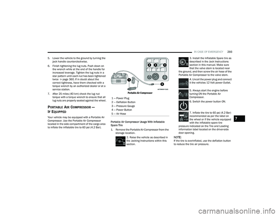
Your vehicle may be equipped with a Portable Air
Compressor. Use the Portable Air Compressor
located in the side compartment of the cargo area
to inflate the inflatable tire to 60 psi (4.2 Bar).
Portable Air Compressor
Portable Air Compressor Usage With Inflatable
Spare Tire
1. Remove the Portable Air Compressor from the storage location.
2. Raise the vehicle as described in
the Jacking Instructions within this
section. 3. Install the Inflatable Spare tire as
described in the Jack Instructions
section in this manual. Make sure
that the valve stem is located near
the ground, and then screw the air hose of the
Portable Air Compressor to the valve stem.
4. Uncoil the power plug and connect
it the vehicles 12 Volt power Outlet.
5. Always start the engine before
turning ON the Portable Air
Compressor.
6. Switch the power button ON.
7. Inflate the tire to 60 psi (4.2 Bar)
recommended as per the label on
the wheel or if the vehicle equipped
with the inflatable spare tire
pressure indicated on the Tire and Loading
information label located on the driver-side
door opening.
NOTE:If the tire is overinflated, use the deflation button
to reduce the tire air pressure.
1 — Power Plug
2 — Deflation Button
3 — Pressure Gauge
4 — Power Button
5 — Air Hose
7
22_RUP_OM_EN_USC_t.book Page 293
Page 362 of 384
360
TECHNICAL SPECIFICATIONS
VEHICLE IDENTIFICATION NUMBER (VIN)
The VIN is on the left front corner of the instrument
panel and is visible from outside of the vehicle
through the windshield.
Vehicle Identification Number
NOTE:It is illegal to remove or alter the VIN.
BRAKE SYSTEM
Your vehicle is equipped with dual hydraulic brake
systems. If either of the two hydraulic systems lose
normal capability, the remaining system will still
function. However, there will be some loss of
overall braking effectiveness. You may notice
increased pedal travel during application, greater
pedal force required to slow or stop, and potential
activation of the Brake Warning Light.
In the event power assist is lost for any reason (i.e.,
repeated brake applications with the engine off)
the brakes will still function. However, the effort
required to brake the vehicle will be much greater
than that required with the power system
operating.
WHEEL AND TIRE TORQUE SPECIFICATIONS
Proper lug nut/bolt torque is very important to
ensure that the wheel is properly mounted to the
vehicle. Any time a wheel has been removed and
reinstalled on the vehicle, the lug nuts/bolts
should be torqued using a properly calibrated
torque wrench using a six-sided (hex) deep wall
socket.
TORQUE SPECIFICATIONS
**Use only authorized dealer recommended lug
nuts/bolts and clean or remove any dirt or oil
before tightening.
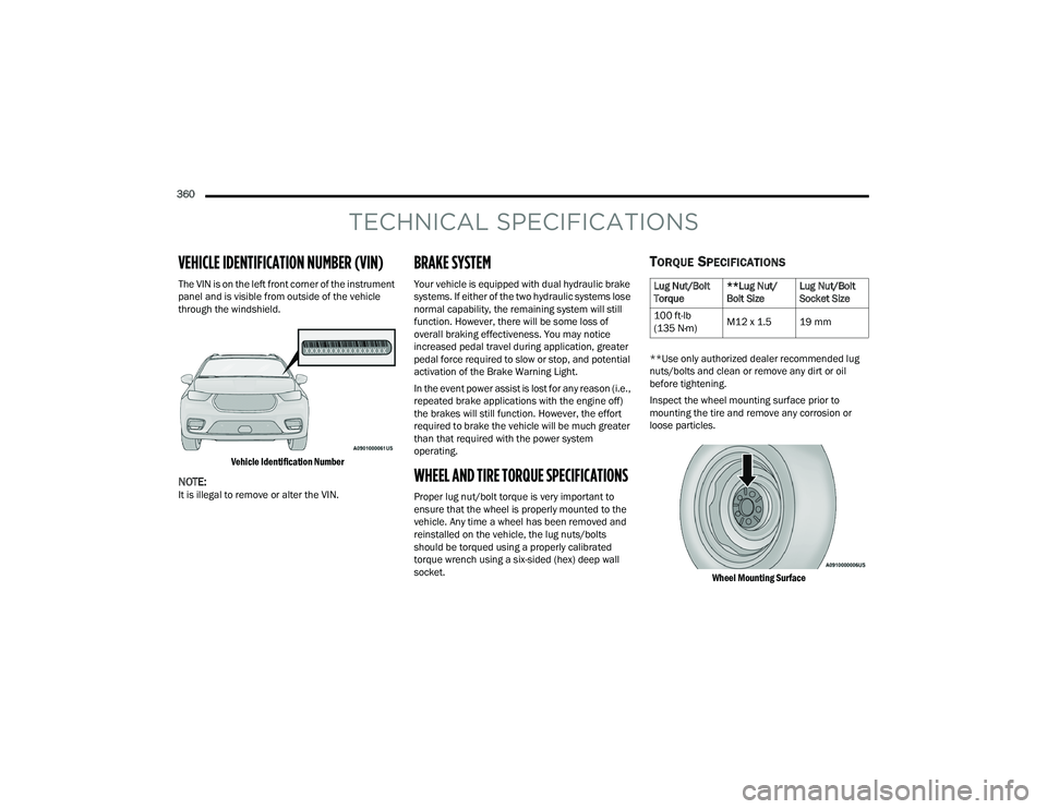
Inspect the wheel mounting surface prior to
mounting the tire and remove any corrosion or
loose particles.
Wheel Mounting Surface
Lug Nut/Bolt
Torque **Lug Nut/
Bolt SizeLug Nut/Bolt
Socket Size
100 ft-lb
(135 N·m) M12 x 1.5 19 mm
22_RUP_OM_EN_USC_t.book Page 360