lug pattern CHRYSLER PACIFICA HYBRID 2023 Owners Manual
[x] Cancel search | Manufacturer: CHRYSLER, Model Year: 2023, Model line: PACIFICA HYBRID, Model: CHRYSLER PACIFICA HYBRID 2023Pages: 328, PDF Size: 16.37 MB
Page 104 of 328
102GETTING TO KNOW YOUR INSTRUMENT PANEL
NOTE:
The charging system is independent from load reduc -
tion. The charging system performs a diagnostic on the
charging system continuously.
If the Battery Charge Warning Light is on it may indicate
a problem with the charging system
Úpage 103.
The electrical loads that may be switched off (if equipped),
and vehicle functions which can be effected by load
reduction:
Heated Seat/Vented Seats/Heated Wheel
Heated/Cooled Cup Holders — If Equipped
Rear Defroster And Heated Mirrors
HVAC System
115 Volts AC Power Inverter System
Audio and Telematics System
Loss of the battery charge may indicate one or more of the
following conditions:
The charging system cannot deliver enough electrical
power to the vehicle system because the electrical
loads are larger than the capability of charging system.
The charging system is still functioning properly.
Turning on all possible vehicle electrical loads (e.g.
HVAC to max settings, exterior and interior lights, over -
loaded power outlets +12 Volts, 150W, USB ports)
during certain driving conditions (city driving, towing,
frequent stopping).
Installing options like additional lights, upfitter elec -
trical accessories, audio systems, alarms and similar
devices.
Unusual driving cycles (short trips separated by long
parking periods).
The vehicle was parked for an extended period of time
(weeks, months).
The battery was recently replaced and was not charged
completely.
The battery was discharged by an electrical load left on
when the vehicle was parked.
The battery was used for an extended period with the
engine not running to supply radio, lights, chargers,
+12 Volt portable appliances like vacuum cleaners,
game consoles and similar devices.
What to do when an electrical load reduction action
message is present (“Battery Saver On” or “Battery Saver
Mode”)
During a trip:
Reduce power to unnecessary loads if possible:
Turn off redundant lights (interior or exterior)
Check what may be plugged in to power outlets
+12 Volts, 150W, USB ports
Check HVAC settings (blower, temperature)
Check the audio settings (volume)
After a trip:
Check if any aftermarket equipment was installed
(additional lights, upfitter electrical accessories, audio
systems, alarms) and review specifications if any (load
and Ignition Off Draw currents).
Evaluate the latest driving cycles (distance, driving
time and parking time).
The vehicle should have service performed if the
message is still present during consecutive trips and
the evaluation of the vehicle and driving pattern did not
help to identify the cause.
WARNING LIGHTS AND MESSAGES
The warning/indicator lights will illuminate in the
instrument panel together with a dedicated message and/
or acoustic signal when applicable. These indications are
indicative and precautionary and as such must not be
considered as exhaustive and/or alternative to the
information contained in the Owner’s Manual, which you
are advised to read carefully in all cases. Always refer to
the information in this chapter in the event of a failure
indication. All active telltales will display first if applicable.
The system check menu may appear different based upon
equipment options and current vehicle status. Some
telltales are optional and may not appear.
RED WARNING LIGHTS
Air Bag Warning Light
This warning light will illuminate to indicate a
fault with the air bag, and will turn on for four to
eight seconds as a bulb check when the ignition
is placed in the ON/RUN or ACC/ON/RUN
position. This light will illuminate with a single chime when a
fault with the air bag has been detected, it will stay on until
the fault is cleared. If the light is either not on during startup,
stays on, or turns on while driving, have the system
inspected at an authorized dealer as soon as possible.
23_RUP_OM_EN_USC_t.book Page 102
Page 236 of 328

234SAFETY
(Continued)
(Continued)
Defroster
Check operation by selecting the defrost mode and place
the blower control on high speed. You should be able to
feel the air directed against the windshield. See an
authorized dealer for service if your defroster is
inoperable.
Floor Mat Safety Information
Always use floor mats designed to fit your vehicle. Only use
a floor mat that does not interfere with the operation of the
accelerator, brake or clutch pedals. Only use a floor mat
that is securely attached using the floor mat fasteners so
it cannot slip out of position and interfere with the
accelerator, brake or clutch pedals or impair safe
operation of your vehicle in other ways.
PERIODIC SAFETY CHECKS YOU SHOULD
M
AKE OUTSIDE THE VEHICLE
Tires
Examine tires for excessive tread wear and uneven wear
patterns. Check for stones, nails, glass, or other objects
lodged in the tread or sidewall. Inspect the tread for cuts
and cracks. Inspect sidewalls for cuts, cracks, and bulges.
Check the lug nut/bolt torque for tightness. Check the
tires (including spare) for proper cold inflation pressure.
WARNING!
An improperly attached, damaged, folded, or stacked
floor mat, or damaged floor mat fasteners may cause
your floor mat to interfere with the accelerator, brake, or
clutch pedals and cause a loss of vehicle control. To
prevent SERIOUS INJURY or DEATH:
ALWAYS securely attach your floor mat
using the floor mat fasteners. DO NOT
install your floor mat upside down or turn
your floor mat over. Lightly pull to confirm
mat is secured using the floor mat
fasteners on a regular basis.
ALWAYS REMOVE THE EXISTING FLOOR
MAT FROM THE VEHICLE before installing
any other floor mat. NEVER install or stack
an additional floor mat on top of an existing
floor mat.
ONLY install floor mats designed to fit your vehicle.
NEVER install a floor mat that cannot be properly
attached and secured to your vehicle. If a floor mat
needs to be replaced, only use a FCA US LLC
approved floor mat for the specific make, model, and
year of your vehicle.
ONLY use the driver’s side floor mat on the driver’s
side floor area. To check for interference, with the
vehicle properly parked with the engine off, fully
depress the accelerator, the brake, and the clutch
pedal (if present) to check for interference. If your
floor mat interferes with the operation of any pedal,
or is not secure to the floor, remove the floor mat
from the vehicle and place the floor mat in your
trunk.
ONLY use the passenger’s side floor mat on the
passenger’s side floor area.
ALWAYS make sure objects cannot fall or slide into
the driver’s side floor area when the vehicle is
moving. Objects can become trapped under acceler -
ator, brake, or clutch pedals and could cause a loss
of vehicle control.
WARNING!
NEVER place any objects under the floor mat (e.g.,
towels, keys, etc.). These objects could change the
position of the floor mat and may cause interference
with the accelerator, brake, or clutch pedals.
If the vehicle carpet has been removed and
re-installed, always properly attach carpet to the floor
and check the floor mat fasteners are secure to the
vehicle carpet. Fully depress each pedal to check for
interference with the accelerator, brake, or clutch
pedals then re-install the floor mats.
It is recommended to only use mild soap and water
to clean your floor mats. After cleaning, always check
your floor mat has been properly installed and is
secured to your vehicle using the floor mat fasteners
by lightly pulling mat.
WARNING!
23_RUP_OM_EN_USC_t.book Page 234
Page 245 of 328
IN CASE OF EMERGENCY243
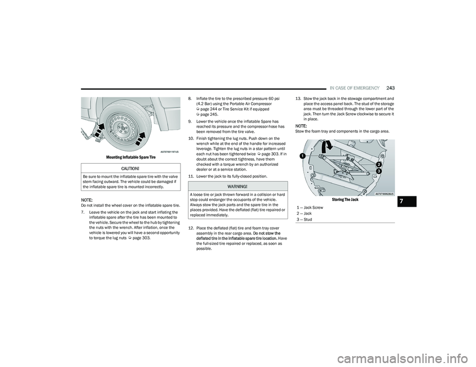
Mounting Inflatable Spare Tire
NOTE:
Do not install the wheel cover on the inflatable spare tire.
7. Leave the vehicle on the jack and start inflating the inflatable spare after the tire has been mounted to
the vehicle. Secure the wheel to the hub by tightening
the nuts with the wrench. After inflation, once the
vehicle is lowered you will have a second opportunity
to torque the lug nuts
Úpage 303. 8. Inflate the tire to the prescribed pressure 60 psi
(4.2 Bar) using the Portable Air Compressor
Úpage 244 or Tire Service Kit if equipped Úpage 245.
9. Lower the vehicle once the inflatable Spare has reached its pressure and the compressor-hose has
been removed from the tire valve.
10. Finish tightening the lug nuts. Push down on the wrench while at the end of the handle for increased
leverage. Tighten the lug nuts in a star pattern until
each nut has been tightened twice
Úpage 303. If in
doubt about the correct tightness, have them
checked with a torque wrench by an authorized
dealer or at a service station.
11. Lower the jack to its fully-closed position.
12. Place the deflated (flat) tire and foam tray cover assembly in the rear cargo area. Do not stow the
deflated tire in the inflatable spare tire location. Have
the full-sized tire repaired or replaced, as soon as
possible. 13. Stow the jack back in the stowage compartment and
place the access panel back. The stud of the storage
area must be threaded through the lower part of the
jack. Then turn the Jack Screw clockwise to secure it
in place.
NOTE:Stow the foam tray and components in the cargo area.
Storing The Jack
CAUTION!
Be sure to mount the inflatable spare tire with the valve
stem facing outward. The vehicle could be damaged if
the inflatable spare tire is mounted incorrectly.
WARNING!
A loose tire or jack thrown forward in a collision or hard
stop could endanger the occupants of the vehicle.
Always stow the jack parts and the spare tire in the
places provided. Have the deflated (flat) tire repaired or
replaced immediately.
1 — Jack Screw
2 — Jack
3 — Stud7
23_RUP_OM_EN_USC_t.book Page 243
Page 246 of 328
244IN CASE OF EMERGENCY
ROAD TIRE INSTALLATION
Vehicles Equipped With Wheel Covers
1. Mount the road tire on the axle.
2. To ease the installation process for steel wheels with
wheel covers, install two lug nuts on the mounting
studs which are on each side of the valve stem. Install
the lug nuts with the cone shaped end of the nut
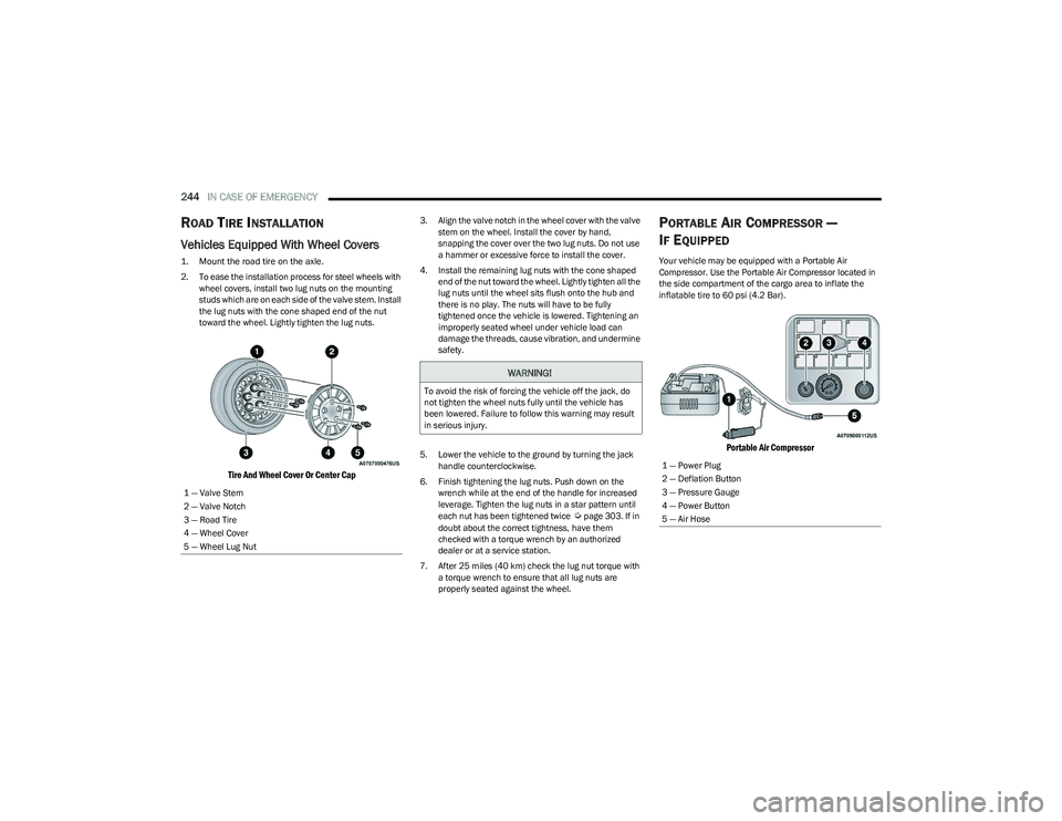
toward the wheel. Lightly tighten the lug nuts.
Tire And Wheel Cover Or Center Cap
3. Align the valve notch in the wheel cover with the valve stem on the wheel. Install the cover by hand,
snapping the cover over the two lug nuts. Do not use
a hammer or excessive force to install the cover.
4. Install the remaining lug nuts with the cone shaped end of the nut toward the wheel. Lightly tighten all the
lug nuts until the wheel sits flush onto the hub and
there is no play. The nuts will have to be fully
tightened once the vehicle is lowered. Tightening an
improperly seated wheel under vehicle load can
damage the threads, cause vibration, and undermine
safety.
5. Lower the vehicle to the ground by turning the jack handle counterclockwise.
6. Finish tightening the lug nuts. Push down on the wrench while at the end of the handle for increased
leverage. Tighten the lug nuts in a star pattern until
each nut has been tightened twice
Úpage 303. If in
doubt about the correct tightness, have them
checked with a torque wrench by an authorized
dealer or at a service station.
7. After 25 miles (40 km) check the lug nut torque with a torque wrench to ensure that all lug nuts are
properly seated against the wheel.
PORTABLE AIR COMPRESSOR —
I
F EQUIPPED
Your vehicle may be equipped with a Portable Air
Compressor. Use the Portable Air Compressor located in
the side compartment of the cargo area to inflate the
inflatable tire to 60 psi (4.2 Bar).
Portable Air Compressor
1 — Valve Stem
2 — Valve Notch
3 — Road Tire
4 — Wheel Cover
5 — Wheel Lug Nut
WARNING!
To avoid the risk of forcing the vehicle off the jack, do
not tighten the wheel nuts fully until the vehicle has
been lowered. Failure to follow this warning may result
in serious injury.
1 — Power Plug
2 — Deflation Button
3 — Pressure Gauge
4 — Power Button
5 — Air Hose
23_RUP_OM_EN_USC_t.book Page 244
Page 293 of 328
SERVICING AND MAINTENANCE291
(Continued)
TIRES — GENERAL INFORMATION
Tire Pressure
Proper tire inflation pressure is essential to the safe and
satisfactory operation of your vehicle. Four primary areas
are affected by improper tire pressure:
Safety
Fuel Economy
Tread Wear
Ride Comfort and Vehicle Stability
Safety Both underinflation and overinflation affect the stability of
the vehicle and can produce a feeling of sluggish response
or over responsiveness in the steering.
NOTE:
Unequal tire pressures from side to side may cause
erratic and unpredictable steering response.
Unequal tire pressure from side to side may cause the
vehicle to drift left or right.
Fuel Economy
Underinflated tires will increase tire rolling resistance
resulting in higher fuel consumption.
Tread Wear
Improper cold tire inflation pressures can cause abnormal
wear patterns and reduced tread life, resulting in the need
for earlier tire replacement. Ride Comfort And Vehicle Stability
Proper tire inflation contributes to a comfortable ride.
Overinflation produces a jarring and uncomfortable ride.
Tire Inflation Pressures
The proper cold tire inflation pressure is listed on the
driver's side B-pillar or rear edge of the driver's side door.
At least once a month:
Check and adjust tire pressure with a good quality
pocket-type pressure gauge. Do not make a visual judg -
ment when determining proper inflation. Tires may look
properly inflated even when they are underinflated.
Inspect tires for signs of tire wear or visible damage.
Inflation pressures specified on the placard are always
“cold tire inflation pressure”. Cold tire inflation pressure is
defined as the tire pressure after the vehicle has not been
driven for at least three hours, or driven less than 1 mile
(1.6 km) after sitting for a minimum of three hours. The
cold tire inflation pressure must not exceed the maximum
inflation pressure molded into the tire sidewall.
WARNING!
Overloading of your tires is dangerous. Overloading can
cause tire failure, affect vehicle handling, and increase
your stopping distance. Use tires of the recommended
load capacity for your vehicle. Never overload them.
WARNING!
Improperly inflated tires are dangerous and can
cause collisions.
Underinflation increases tire flexing and can result in
overheating and tire failure.
Overinflation reduces a tire's ability to cushion shock.
Objects on the road and chuckholes can cause
damage that result in tire failure.
Overinflated or underinflated tires can affect vehicle
handling and can fail suddenly, resulting in loss of
vehicle control.
Unequal tire pressures can cause steering problems.
You could lose control of your vehicle.
Unequal tire pressures from one side of the vehicle
to the other can cause the vehicle to drift to the right
or left.
Always drive with each tire inflated to the recom -
mended cold tire inflation pressure.
WARNING!
CAUTION!
After inspecting or adjusting the tire pressure, always
reinstall the valve stem cap. This will prevent moisture
and dirt from entering the valve stem, which could
damage the valve stem.
8
23_RUP_OM_EN_USC_t.book Page 291
Page 306 of 328
304TECHNICAL SPECIFICATIONS
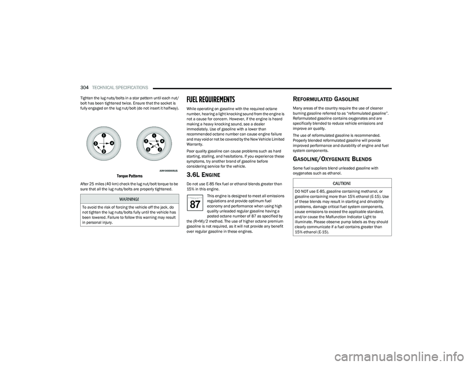
Tighten the lug nuts/bolts in a star pattern until each nut/
bolt has been tightened twice. Ensure that the socket is
fully engaged on the lug nut/bolt (do not insert it halfway).
Torque Patterns
After 25 miles (40 km) check the lug nut/bolt torque to be
sure that all the lug nuts/bolts are properly tightened.
FUEL REQUIREMENTS
While operating on gasoline with the required octane
number, hearing a light knocking sound from the engine is
not a cause for concern. However, if the engine is heard
making a heavy knocking sound, see a dealer
immediately. Use of gasoline with a lower than
recommended octane number can cause engine failure
and may void or not be covered by the New Vehicle Limited
Warranty.
Poor quality gasoline can cause problems such as hard
starting, stalling, and hesitations. If you experience these
symptoms, try another brand of gasoline before
considering service for the vehicle.
3.6L ENGINE
Do not use E-85 flex fuel or ethanol blends greater than
15% in this engine.
This engine is designed to meet all emissions
regulations and provide optimum fuel
economy and performance when using high
quality unleaded regular gasoline having a
posted octane number of 87 as specified by
the (R+M)/2 method. The use of higher octane premium
gasoline is not required, as it will not provide any benefit
over regular gasoline in these engines.
REFORMULATED GASOLINE
Many areas of the country require the use of cleaner
burning gasoline referred to as “reformulated gasoline”.
Reformulated gasoline contains oxygenates and are
specifically blended to reduce vehicle emissions and
improve air quality.
The use of reformulated gasoline is recommended.
Properly blended reformulated gasoline will provide
improved performance and durability of engine and fuel
system components.
GASOLINE/OXYGENATE BLENDS
Some fuel suppliers blend unleaded gasoline with
oxygenates such as ethanol.
WARNING!
To avoid the risk of forcing the vehicle off the jack, do
not tighten the lug nuts/bolts fully until the vehicle has
been lowered. Failure to follow this warning may result
in personal injury.
CAUTION!
DO NOT use E-85, gasoline containing methanol, or
gasoline containing more than 15% ethanol (E-15). Use
of these blends may result in starting and drivability
problems, damage critical fuel system components,
cause emissions to exceed the applicable standard,
and/or cause the Malfunction Indicator Light to
illuminate. Please observe pump labels as they should
clearly communicate if a fuel contains greater than
15% ethanol (E-15).
23_RUP_OM_EN_USC_t.book Page 304