tow CHRYSLER PT CRUISER 2010 1.G Owner's Manual
[x] Cancel search | Manufacturer: CHRYSLER, Model Year: 2010, Model line: PT CRUISER, Model: CHRYSLER PT CRUISER 2010 1.GPages: 60, PDF Size: 6.19 MB
Page 33 of 60
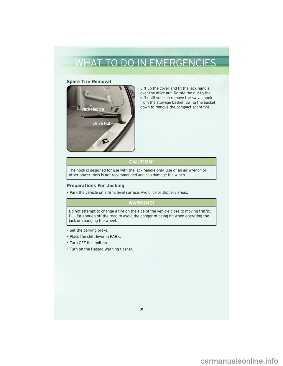
Spare Tire Removal
• Lift up the cover and fit the jack-handleover the drive nut. Rotate the nut to the
left until you can remove the swivel hook
from the stowage basket. Swing the basket
down to remove the compact spare tire.
CAUTION!
The hook is designed for use with the jack handle only. Use of an air wrench or
other power tools is not recommended and can damage the winch.
Preparations For Jacking
• Park the vehicle on a firm, level surface. Avoid ice or slippery areas.
WARNING!
Do not attempt to change a tire on the side of the vehicle close to moving traffic.
Pull far enough off the road to avoid the danger of being hit when operating the
jack or changing the wheel.
• Set the parking brake.
• Place the shift lever in PARK.
• Turn OFF the ignition.
• Turn on the Hazard Warning flasher.
31
WHAT TO DO IN EMERGENCIES
Page 34 of 60
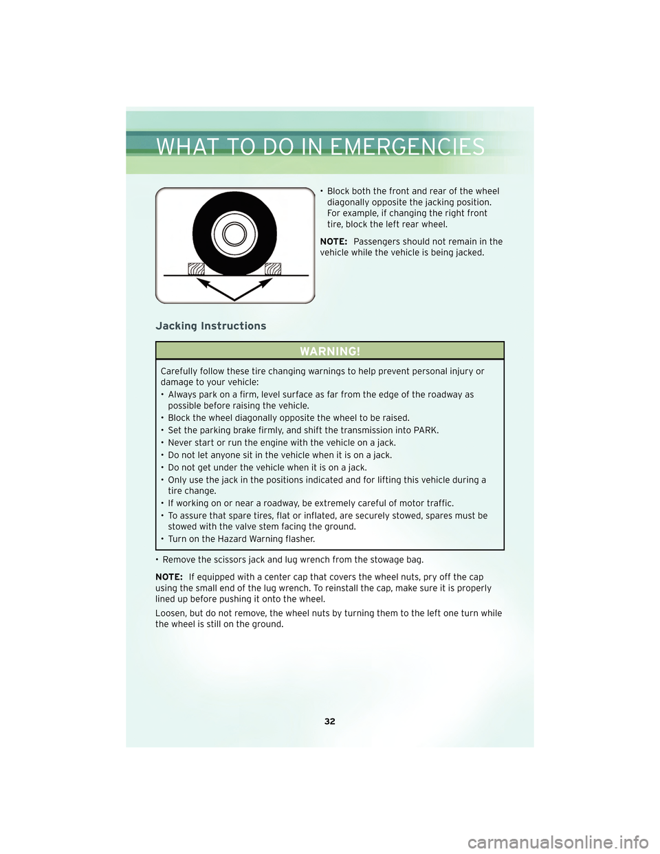
• Block both the front and rear of the wheeldiagonally opposite the jacking position.
For example, if changing the right front
tire, block the left rear wheel.
NOTE: Passengers should not remain in the
vehicle while the vehicle is being jacked.
Jacking Instructions
WARNING!
Carefully follow these tire changing warnings to help prevent personal injury or
damage to your vehicle:
• Always park on a firm, level surface as far from the edge of the roadway as possible before raising the vehicle.
• Block the wheel diagonally opposite the wheel to be raised.
• Set the parking brake firmly, and shift the transmission into PARK.
• Never start or run the engine with the vehicle on a jack.
• Do not let anyone sit in the vehicle when it is on a jack.
• Do not get under the vehicle when it is on a jack.
• Only use the jack in the positions indicated and for lifting this vehicle during a tire change.
• If working on or near a roadway, be extremely careful of motor traffic.
• To assure that spare tires, flat or inflated, are securely stowed, spares must be stowed with the valve stem facing the ground.
• Turn on the Hazard Warning flasher.
• Remove the scissors jack and lug wrench from the stowage bag.
NOTE: If equipped with a center cap that covers the wheel nuts, pry off the cap
using the small end of the lug wrench. To reinstall the cap, make sure it is properly
lined up before pushing it onto the wheel.
Loosen, but do not remove, the wheel nuts by turning them to the left one turn while
the wheel is still on the ground.
WHAT TO DO IN EMERGENCIES
32
Page 35 of 60
CAUTION!
Do not attempt to raise the vehicle by jacking on the cross-member below the
radiator, on the front suspension cross-member, or on the rear axle assembly.
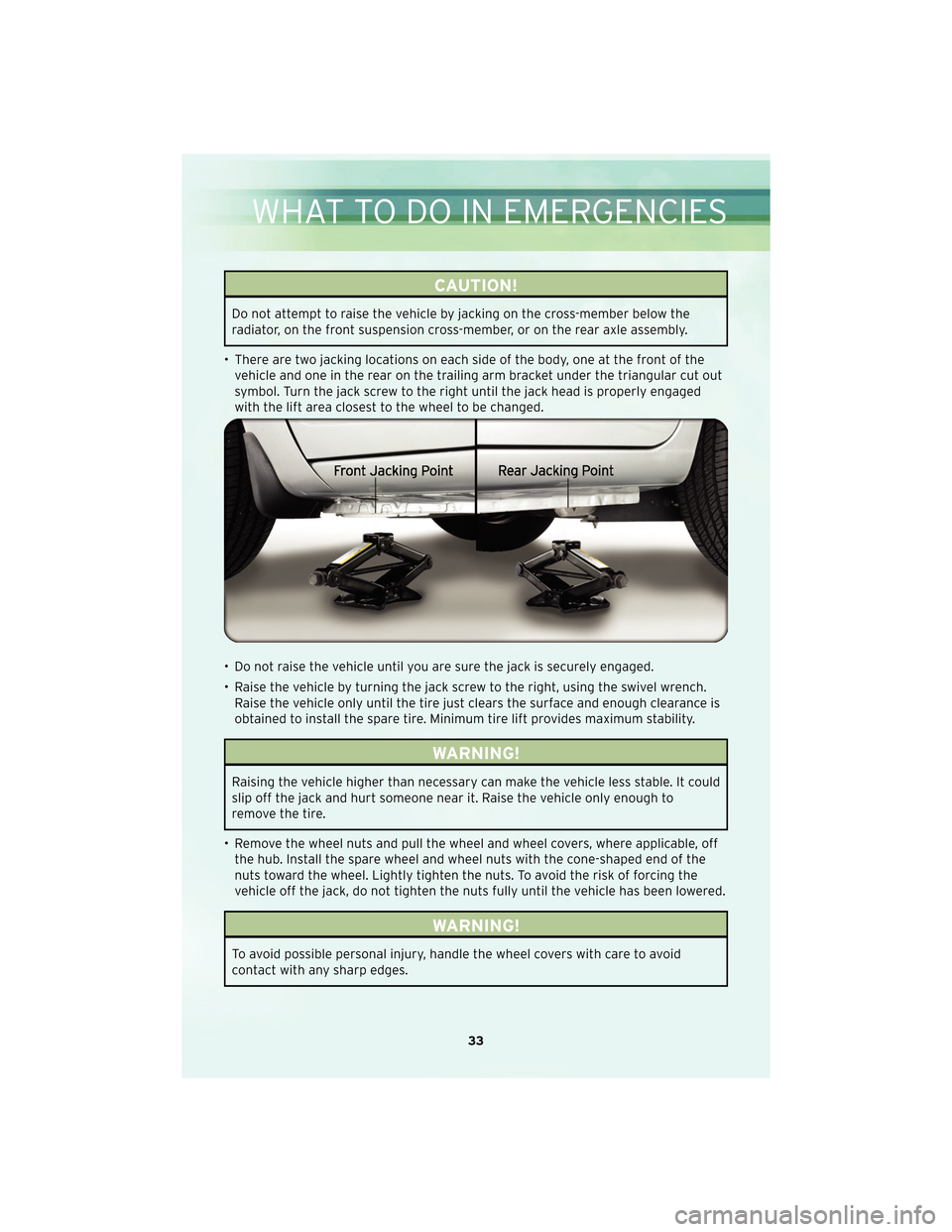
• There are two jacking locations on each side of the body, one at the front of the vehicle and one in the rear on the trailing arm bracket under the triangular cut out
symbol. Turn the jack screw to the right until the jack head is properly engaged
with the lift area closest tothe wheel to be changed.
• Do not raise the vehicle until you are sure the jack is securely engaged.
• Raise the vehicle by turning the jack screw to the right, using the swivel wrench. Raise the vehicle only until the tire just clears the surface and enough clearance is
obtained to install the spare tire. Minimum tire lift provides maximum stability.
WARNING!
Raising the vehicle higher than necessary can make the vehicle less stable. It could
slip off the jack and hurt someone near it. Raise the vehicle only enough to
remove the tire.
• Remove the wheel nuts and pull the wheel and wheel covers, where applicable, off the hub. Install the spare wheel and wheel nuts with the cone-shaped end of the
nuts toward the wheel. Lightly tighten the nuts. To avoid the risk of forcing the
vehicle off the jack, do not tighten the nuts fully until the vehicle has been lowered.
WARNING!
To avoid possible personal injury, handle the wheel covers with care to avoid
contact with any sharp edges.
33
WHAT TO DO IN EMERGENCIES
Page 36 of 60
NOTE:The wheel cover is held on the wheel by the wheel nuts. When reinstalling
original wheel, properly align the wheel cover to the valve stem, place the wheel
cover onto the wheel, then install the wheel nuts.
• Lower the vehicle by turning the jack screw to the left.
• Finish tightening the nuts. Push down on the wrench while tightening the wheel nuts. Alternate nuts until each nut has been tightened twice. The correct wheel nut
torque is 100 ft lbs (135 N m). If you doubt that you have tightened the nuts
correctly, have them checked with a torque wrench by your authorized dealer or at
a qualified service station.
• Remove the wheel blocks and lower the jack until it is free. Stow the lug wrench and jack in their designated location. Secure all parts using the means provided.
WARNING!
A loose tire or jack thrown forward in a collision or hard stop could endanger the
occupants of the vehicle. Always stow the jack parts and the spare tire in the
places provided. Have the deflated (flat) tire repaired or replaced immediately.
• Place the deflated (flat) tire in the cargo area; have the tire repaired or replaced
as soon as possible.
• Check the tire pressure as soon as possible. Correct the pressure as required.
JUMP-STARTING
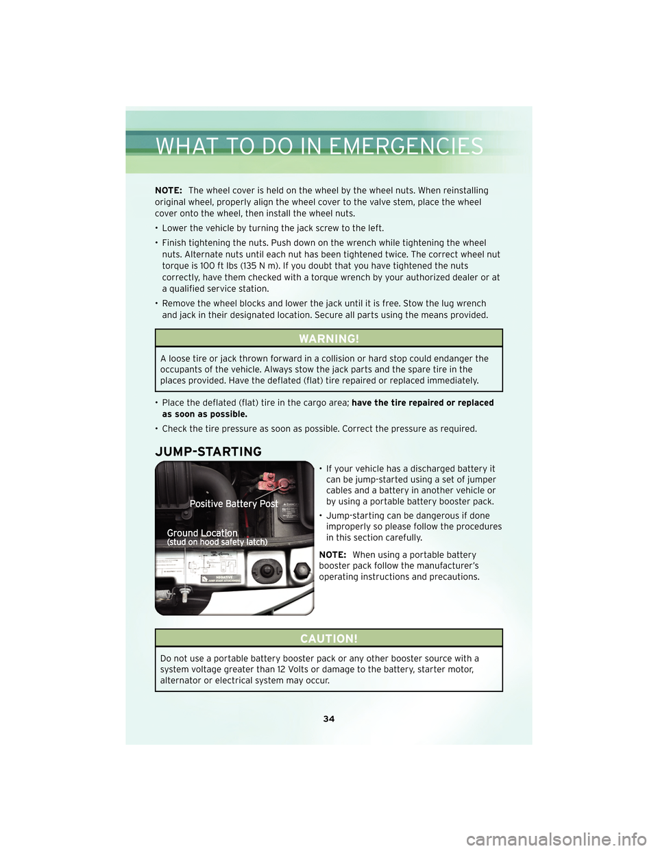
• If your vehicle has a discharged battery it can be jump-started using a set of jumper
cables and a battery in another vehicle or
by using a portable battery booster pack.
• Jump-starting can be dangerous if done improperly so please follow the procedures
in this section carefully.
NOTE: When using a portable battery
booster pack follow the manufacturer’s
operating instructions and precautions.
CAUTION!
Do not use a portable battery booster pack or any other booster source with a
system voltage greater than 12 Volts or damage to the battery, starter motor,
alternator or electrical system may occur.
WHAT TO DO IN EMERGENCIES
34
Page 40 of 60

TOWING A DISABLED VEHICLEModelFlat Towing (all four
wheels on the ground)Flatbed Towing (all
four wheels
suspended OFF the
ground)Front Wheels Raised,
Rear Wheels on the
Ground
Rear Wheels Raised,
Front Wheels on the
Ground
Without a Key NOT Permitted Recommended Method May Be Used
NOT Permitted without
a front end dolly
WithaKey Shift lever must be in
*NEUTRAL. The
distance to be traveled
must not exceed 15 mi
(25 km), and the
towing speed must not
exceed 25 mph
(40 km/h).Recommended Method May Be Used
NOT Permitted without
a front end dolly
38
WHAT TO DO IN EMERGENCIES
Page 46 of 60
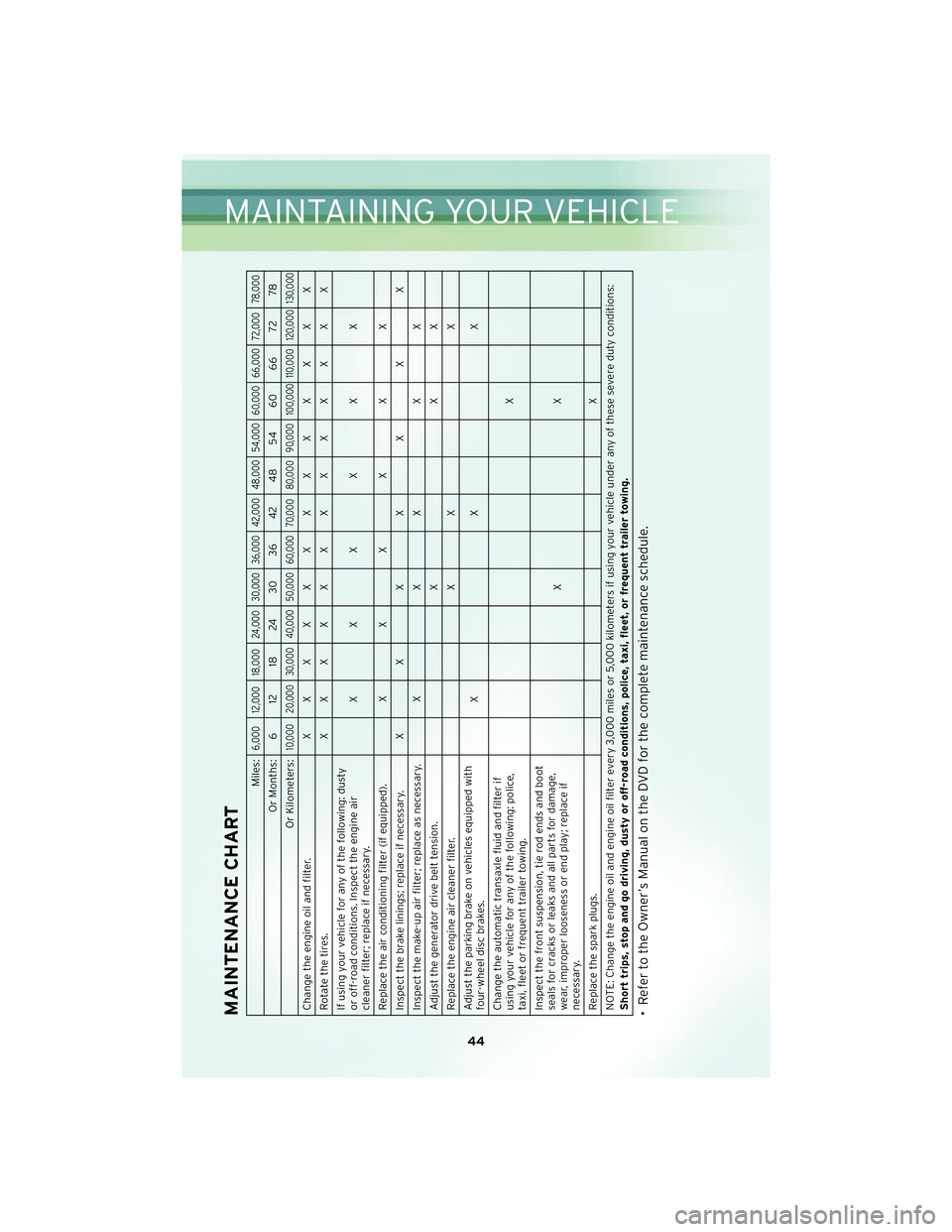
MAINTENANCE CHART
Miles:
6,000 12,000 18,000 24,000 30,000 36,000 42,000 48,000 54,000 60,000 66,000 72,000 78,000
Or Months: 6 12 18 24 30 36 42 48 54 60 66 72 78
Or Kilometers:
10,000 20,000 30,000 40,000 50,000 60,000 70,000 80,000 90,000 100,000 110,000 120,000 130,000
Change the engine oil and filter. XXXXXXXXXXXXX
Rotatethetires. XXXXXXXXXXXXX
If using your vehicle for any of the following: dusty
or off-road conditions. Inspect the engine air
cleaner filter; replace if necessary. XXXXXX
Replace the air conditioning filter (if equipped). X X X X X X
Inspect the brake linings; replace if necessary. X X X X X X X
Inspect the make-up air filter; replace as necessary. X X X X X
Adjust the generator drive belt tension. X X X
Replace the engine air cleaner filter. X X X
Adjust the parking brake on vehicles equipped with
four-wheel disc brakes. XXX
Change the automatic transaxle fluid and filter if
using your vehicle for any of the following: police,
taxi, fleet or frequent trailer towing. X
Inspect the front suspension, tie rod ends and boot
seals for cracks or leaks and all parts for damage,
wear, improper looseness or end play; replace if
necessary. XX
Replace the spark plugs. X
NOTE: Change the engine oil and engine oil filter every 3,000 miles or 5,000 kilometers if using your vehicle under any of these severe duty conditions:
Short trips, stop and go driving, dusty or off-road conditions, police, taxi, fleet, or frequent trailer towing.• Refer to the Owner’s Manual on the DVD for the complete maintenance schedule.
44
MAINTAINING YOUR VEHICLE
Page 48 of 60
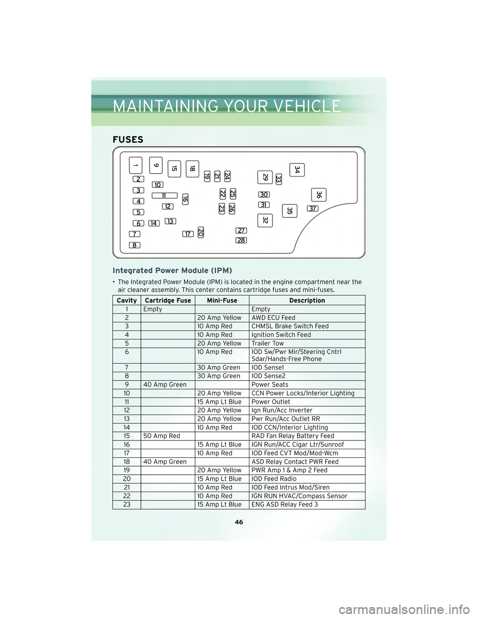
FUSES
Integrated Power Module (IPM)
• The Integrated Power Module (IPM) is located in the engine compartment near theair cleaner assembly. This center contains cartridge fuses and mini-fuses.
Cavity Cartridge Fuse Mini-Fuse Description
1 Empty Empty
2 20 Amp Yellow AWD ECU Feed
3 10 Amp Red CHMSL Brake Switch Feed
4 10 Amp Red Ignition Switch Feed
5 20 Amp Yellow Trailer Tow
6 10 Amp Red IOD Sw/Pwr Mir/Steering Cntrl
Sdar/Hands-Free Phone
7 30 Amp Green IOD Sense1
8 30 Amp Green IOD Sense2
9 40 Amp Green Power Seats
10 20 Amp Yellow CCN Power Locks/Interior Lighting
11 15 Amp Lt Blue Power Outlet
12 20 Amp Yellow Ign Run/Acc Inverter
13 20 Amp Yellow Pwr Run/Acc Outlet RR
14 10 Amp Red IOD CCN/Interior Lighting
15 50 Amp Red RAD Fan Relay Battery Feed
16 15 Amp Lt Blue IGN Run/ACC Cigar Ltr/Sunroof
17 10 Amp Red IOD Feed CVT Mod/Mod-Wcm
18 40 Amp Green ASD Relay Contact PWR Feed
19 20 Amp Yellow PWR Amp1&Amp2Feed
20 15 Amp Lt Blue IOD Feed Radio
21 10 Amp Red IOD Feed Intrus Mod/Siren
22 10 Amp Red IGN RUN HVAC/Compass Sensor
23 15 Amp Lt Blue ENG ASD Relay Feed 3
MAINTAINING YOUR VEHICLE
46