seats CHRYSLER PT CRUISER 2010 1.G User Guide
[x] Cancel search | Manufacturer: CHRYSLER, Model Year: 2010, Model line: PT CRUISER, Model: CHRYSLER PT CRUISER 2010 1.GPages: 60, PDF Size: 6.19 MB
Page 3 of 60
INTRODUCTION/WELCOME
WELCOME FROM
CHRYSLER GROUP LLC......... 2
CONTROLS AT A GLANCE
DRIVER COCKPIT.............4
INSTRUMENT CLUSTER .........6
GETTING STARTED
KEYFOB ..................8
THEFT ALARM..............8
SEATBELT ................9
CHILD RESTRAINTS ...........9
FRONTSEATS...............11
TILT STEERING COLUMN ........13
PROGRAMMABLE FEATURES ......14
OPERATING YOUR VEHICLE
TURN SIGNAL/LIGHTS LEVER .....15
WIPER/WASHER LEVER .........16
SPEED CONTROL LEVER ........17
POWER WINDOWS ............18
SLIDING CENTER ARMREST .......18
TUMBLING REAR SEAT/SEAT
REMOVAL .................19
CLIMATE CONTROLS .......... 20
POWERSUNROOF ........... 20
WIND BUFFETING .............21
ELECTRONICS
NON-TOUCH-SCREEN RADIO ......22
ELECTRONIC VEHICLE INFORMATION
CENTER (EVIC) ..............23
UNIVERSAL GARAGE DOOR OPENER .23
POWER OUTLET ............ 25
UTILITY
TRAILER TOWING WEIGHTS
(MAXIMUM TRAILER WEIGHT
RATINGS)................ 26
RECREATIONAL TOWING (BEHIND
MOTORHOME, ETC.) .......... 26 BRAKE/TRANSMISSION INTERLOCK
SYSTEM ................. 26
WHAT TO DO IN EMERGENCIES
24 HOUR TOWING ASSISTANCE -
U.S. ONLY
.................27
INSTRUMENT CLUSTER WARNING
LIGHTS ...................27
IF YOUR ENGINE OVERHEATS .... 29
JACKING AND TIRE CHANGING .... 30
JUMP-STARTING ............ 34
TOWING A DISABLED VEHICLE .... 38
FREEING A STUCK VEHICLE ...... 39
EVENT DATA RECORDER (EDR) . . . 40
MAINTAINING YOUR VEHICLE
OPENING THE HOOD ...........41
ENGINE COMPARTMENT ....... 42
FLUIDS AND CAPACITIES ....... 43
MAINTENANCE CHART ........ 44
FUSES .................. 46
TIREPRESSURES............ 47
WHEEL AND WHEEL TRIM CARE . . . 48
EXTERIOR BULBS ............ 48
CONSUMER ASSISTANCE
CHRYSLER GROUP LLC CUSTOMER
CENTER ................. 49
CHRYSLER CANADA INC.
CUSTOMER CENTER .......... 49
ASSISTANCE FOR THE HEARING
IMPAIRED ................ 49
PUBLICATIONS ORDERING ...... 49
REPORTING SAFETY DEFECTS IN
THE 50 UNITED STATES AND
WASHINGTON, D.C. ........... 50
TIREWARRANTY ............ 50
MOPAR ACCESSORIES
MOPAR®ACCESSORIES ........ 53
TABLE OF CONTENTS
Page 11 of 60
SEAT BELT
• Be sure everyone in your vehicle is in a seat and using a seat belt properly.
WARNING!
In a collision, you and your passengers can suffer much greater injuries if you are
not properly buckled up. You can strike the interior of your vehicle or other
passengers, or you can be thrown out of the vehicle. Always be sure you and
others in your vehicle are buckled up properly.
CHILD RESTRAINTS
• Every state in the United States and all Canadian provinces require that smallchildren ride in proper restraint systems. This is the law, and you can be prosecuted
for ignoring it.
WARNING!
In a collision, an unrestrained child, even a tiny baby, can become a projectile
inside the vehicle. The force required to hold even an infant on your lap could
become so great that you could not hold the child, no matter how strong you are.
The child and others could be badly injured. Any child riding in your vehicle should
be in a proper restraint for the child’s size.
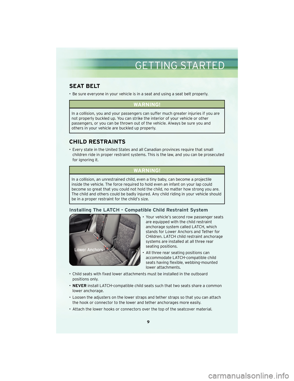
Installing The LATCH - Compatible Child Restraint System
• Your vehicle’s second row passenger seatsare equipped with the child restraint
anchorage system called LATCH, which
stands for Lower Anchors and Tether for
CHildren. LATCH child restraint anchorage
systems are installed at all three rear
seating positions.
• All three rear seating positions can accommodate LATCH-compatible child
seats having flexible, webbing-mounted
lower attachments.
• Child seats with fixed lower attachments must be installed in the outboard positions only.
• NEVER install LATCH-compatible child seats such that two seats share a common
lower anchorage.
• Loosen the adjusters on the lower straps and tether straps so that you can attach the hook or connector to the lower and tether anchorages more easily.
• Attach the lower hooks or connectors over the top of the seatcover material.
9
GETTING STARTED
Page 12 of 60
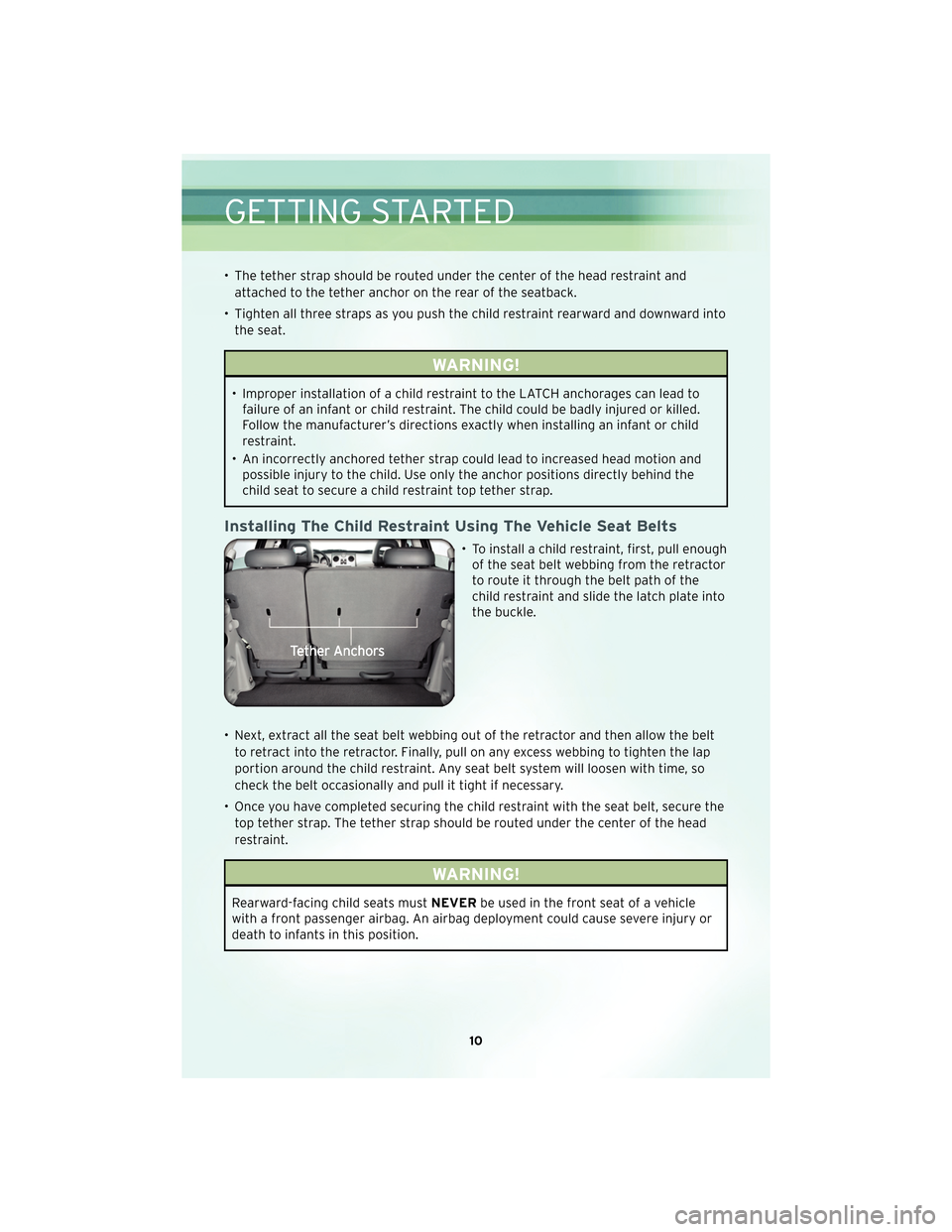
• The tether strap should be routed under the center of the head restraint andattached to the tether anchor on the rear of the seatback.
• Tighten all three straps as you push the child restraint rearward and downward into the seat.
WARNING!
• Improper installation of a child restraint to the LATCH anchorages can lead tofailure of an infant or child restraint. The child could be badly injured or killed.
Follow the manufacturer’s directions exactly when installing an infant or child
restraint.
• An incorrectly anchored tether strap could lead to increased head motion and possible injury to the child. Use only the anchor positions directly behind the
child seat to secure a child restraint top tether strap.
Installing The Child Restraint Using The Vehicle Seat Belts
• To install a child restraint, first, pull enoughof the seat belt webbing from the retractor
to route it through the belt path of the
child restraint and slide the latch plate into
the buckle.
• Next, extract all the seat belt webbing out of the retractor and then allow the belt to retract into the retractor. Finally, pull on any excess webbing to tighten the lap
portion around the child restraint. Any seat belt system will loosen with time, so
check the belt occasionally and pull it tight if necessary.
• Once you have completed securing the child restraint with the seat belt, secure the top tether strap. The tether strap should be routed under the center of the head
restraint.
WARNING!
Rearward-facing child seats must NEVERbe used in the front seat of a vehicle
with a front passenger airbag. An airbag deployment could cause severe injury or
death to infants in this position.
GETTING STARTED
10
Page 13 of 60
FRONT SEATS
WARNING!
Adjusting a seat while the vehicle is moving is dangerous. The sudden movement
of the seat could cause you to lose control. The seat belt might not be properly
adjusted, and you could be injured. Only adjust a seat while the vehicle is parked.
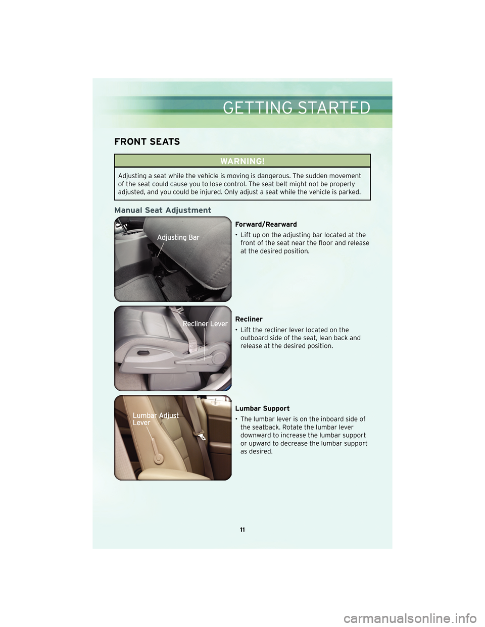
Manual Seat Adjustment
Forward/Rearward
• Lift up on the adjusting bar located at thefront of the seat near the floor and release
at the desired position.
Recliner
• Lift the recliner lever located on theoutboard side of the seat, lean back and
release at the desired position.
Lumbar Support
• The lumbar lever is on the inboard side ofthe seatback. Rotate the lumbar lever
downward to increase the lumbar support
or upward to decrease the lumbar support
as desired.
11
GETTING STARTED
Page 14 of 60

Six-Way Power Seats
• The power seat switch is located on theoutboard side of the seat near the floor.
Use the switch to move the seat up, down,
forward, rearward, or to tilt the seat.
CAUTION!
DO NOT place any article under a power seat or impede its ability to move as it
may cause damage to the seat controls. Seat travel may become limited if
movement is stopped by an obstruction in the seat’s path.
Heated Seats
• The controls for the front heated seats arelocated on the center instrument panel
area.
• Press the switch once to select High-level heating. Press the switch a second time to
select Low-level heating. Press the switch a
third time to shut the heating elements
Off.
WARNING!
• Persons who are unable to feel pain to the skin because of advanced age,chronic illness, diabetes, spinal cord injury, medication, alcohol use, exhaustion
or other physical conditions must exercise care when using the seat heater. It
may cause burns even at low temperatures, especially if used for long periods of
time.
• Do not place anything on the seat that insulates against heat, such as a blanket or cushion. This may cause the seat heater to overheat. Sitting in a seat that has
been overheated could cause serious burns due to the increased surface
temperature of the seat.
GETTING STARTED
12
Page 21 of 60
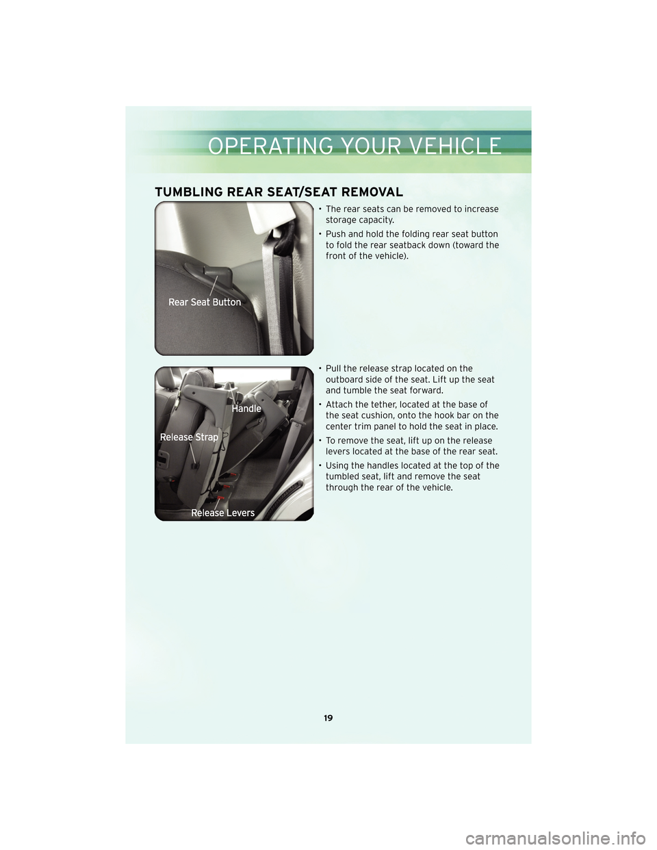
TUMBLING REAR SEAT/SEAT REMOVAL
• The rear seats can be removed to increasestorage capacity.
• Push and hold the folding rear seat button to fold the rear seatback down (toward the
front of the vehicle).
• Pull the release strap located on the outboard side of the seat. Lift up the seat
and tumble the seat forward.
• Attach the tether, located at the base of the seat cushion, onto the hook bar on the
center trim panel to hold the seat in place.
• To remove the seat, lift up on the release levers located at the base of the rear seat.
• Using the handles located at the top of the tumbled seat, lift and remove the seat
through the rear of the vehicle.
19
OPERATING YOUR VEHICLE
Page 48 of 60
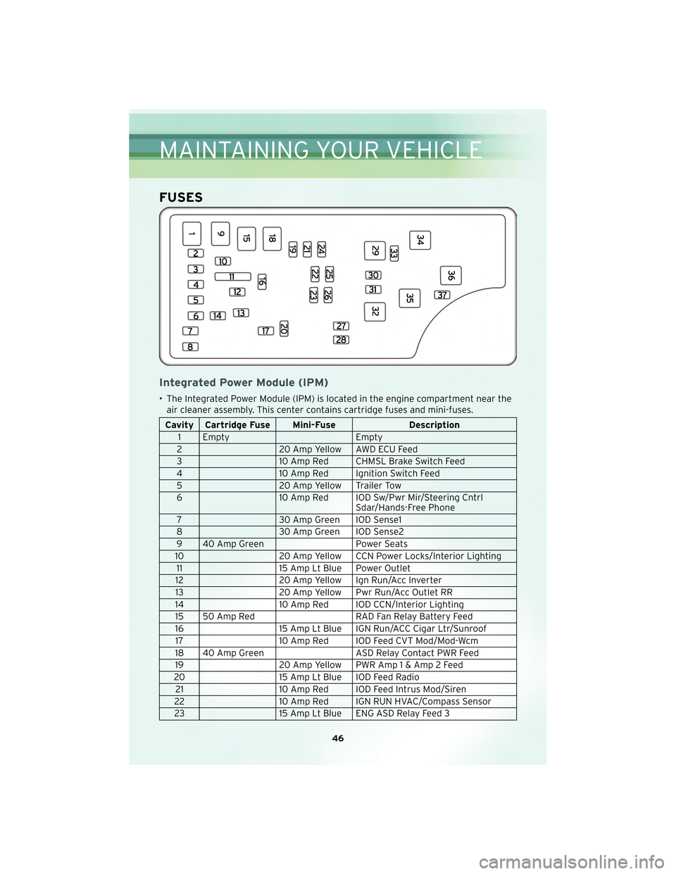
FUSES
Integrated Power Module (IPM)
• The Integrated Power Module (IPM) is located in the engine compartment near theair cleaner assembly. This center contains cartridge fuses and mini-fuses.
Cavity Cartridge Fuse Mini-Fuse Description
1 Empty Empty
2 20 Amp Yellow AWD ECU Feed
3 10 Amp Red CHMSL Brake Switch Feed
4 10 Amp Red Ignition Switch Feed
5 20 Amp Yellow Trailer Tow
6 10 Amp Red IOD Sw/Pwr Mir/Steering Cntrl
Sdar/Hands-Free Phone
7 30 Amp Green IOD Sense1
8 30 Amp Green IOD Sense2
9 40 Amp Green Power Seats
10 20 Amp Yellow CCN Power Locks/Interior Lighting
11 15 Amp Lt Blue Power Outlet
12 20 Amp Yellow Ign Run/Acc Inverter
13 20 Amp Yellow Pwr Run/Acc Outlet RR
14 10 Amp Red IOD CCN/Interior Lighting
15 50 Amp Red RAD Fan Relay Battery Feed
16 15 Amp Lt Blue IGN Run/ACC Cigar Ltr/Sunroof
17 10 Amp Red IOD Feed CVT Mod/Mod-Wcm
18 40 Amp Green ASD Relay Contact PWR Feed
19 20 Amp Yellow PWR Amp1&Amp2Feed
20 15 Amp Lt Blue IOD Feed Radio
21 10 Amp Red IOD Feed Intrus Mod/Siren
22 10 Amp Red IGN RUN HVAC/Compass Sensor
23 15 Amp Lt Blue ENG ASD Relay Feed 3
MAINTAINING YOUR VEHICLE
46