engine CHRYSLER SEBRING 2004 2.G User Guide
[x] Cancel search | Manufacturer: CHRYSLER, Model Year: 2004, Model line: SEBRING, Model: CHRYSLER SEBRING 2004 2.GPages: 273, PDF Size: 4.88 MB
Page 70 of 273

When Climbing A Hill
If vehicle speed drops 3 mph (5 km/h) below the Speed
Control set speed, the transaxle will downshift to third
gear. Under severe conditions the transaxle may down-
shift again to second gear. The transaxle will upshift to
fourth gear after the vehicle has reached the top of the
hill.
When Descending A Hill
If vehicle speed rises 3 mph (5 km/h) over the Speed
Control set speed, the transaxle will downshift to third
gear. This provides engine braking to keep vehicle speed
under control. The transaxle will not downshift below
third gear to control vehicle overspeed. The transaxle will
upshift to fourth gear after the vehicle has reached the
bottom of the hill.
NOTE:On very steep hills, a greater speed loss or gain
may occur. It may be preferable to drive without Speed
Control.
Rolling Hills
The transaxle may downshift into third gear and remain
there as the vehicle travels over rolling hills. The trans-
axle will upshift into fourth gear when the road flattens
out.
The transaxle will resume its normal shift schedule if you
depress the accelerator pedal during any of the above
conditions.
WARNING!
Speed Control can be dangerous where the system
can't maintain a constant speed. Your vehicle could
go too fast for the conditions, and you could lose
control. An accident could be the result. Don't use
Speed Control in heavy traffic or on roads that are
winding, icy, snow-covered, or slippery.
70 UNDERSTANDING THE FEATURES OF YOUR VEHICLE
Page 71 of 273

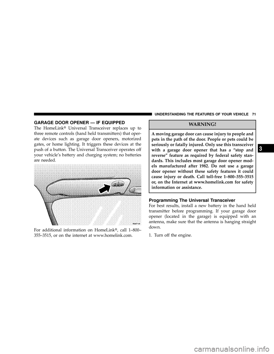
GARAGE DOOR OPENER Ð IF EQUIPPED
The HomeLinktUniversal Transceiver replaces up to
three remote controls (hand held transmitters) that oper-
ate devices such as garage door openers, motorized
gates, or home lighting. It triggers these devices at the
push of a button. The Universal Transceiver operates off
your vehicle's battery and charging system; no batteries
are needed.
For additional information on HomeLinkt, call 1±800±
355±3515, or on the internet at www.homelink.com.WARNING!
A moving garage door can cause injury to people and
pets in the path of the door. People or pets could be
seriously or fatally injured. Only use this transceiver
with a garage door opener that has a ªstop and
reverseº feature as required by federal safety stan-
dards. This includes most garage door opener mod-
els manufactured after 1982. Do not use a garage
door opener without these safety features it could
cause injury or death. Call toll-free 1±800±355±3515
or, on the Internet at www.homelink.com for safety
information or assistance.
Programming The Universal Transceiver
For best results, install a new battery in the hand held
transmitter before programming. If your garage door
opener (located in the garage) is equipped with an
antenna, make sure that the antenna is hanging straight
down.
1. Turn off the engine.
UNDERSTANDING THE FEATURES OF YOUR VEHICLE 71
3
Page 78 of 273

CAUTION!
Electrical Outlet Use With Engine Off
²Many accessories that can be plugged in draw
power from the vehicle's battery, even when not
in use (i.e., cellular phones, etc.). Eventually, if
plugged in long enough, the vehicle's battery will
discharge sufficiently to degrade battery life
and/or prevent engine starting.
²Accessories that draw higher power (i.e., coolers,
vacuum cleaners, lights, etc.) will degrade the
battery even more quickly. Only use these inter-
mittently and with greater caution.
²After the use of high power draw accessories, or
long periods of the vehicle not being started (with
accessories still plugged in), the vehicle must be
driven a sufficient length of time to allow the
alternator to recharge the vehicle's battery.
78 UNDERSTANDING THE FEATURES OF YOUR VEHICLE
Page 87 of 273

5. Tachometer
The red area of the scale shows the maximum permissible
engine revolutions-per-minute (rpm x 1000) for each gear
range. Before reaching the red area (over 6,500 rpm), ease
up on the accelerator to prevent engine over speed.
6. Turn Signal Indicators
The arrows will flash in unison with the exterior turn
signal, when using the turn signal lever.
7. High Beam Indicator
This light shows that the headlights are on high
beam. Pull the turn signal lever toward the
steering wheel to switch the headlights from high or
low beam.
8. Speedometer
Shows the vehicle speed in miles-per-hour and
kilometers-per-hour.
9. Charging System Light
This light shows the status of the electrical
charging system. The light should come on
briefly when the ignition is first turned on and remain
on briefly as a bulb check. If the light stays on orcomes on while driving, turn off some of the vehicle's
electrical devices, such as the Fog Lights or Rear
Defroster. If the Charging System Light remains on, it
means that the vehicle is experiencing a problem with
the charging system. Obtain SERVICE IMMEDI-
ATELY. See your local authorized dealer.
10. Malfunction Indicator Light
This light is part of an onboard diagnostic
system called OBD that monitors engine and
automatic transmission control systems. The
light will illuminate as long as the key is in the ON
position, prior to engine start up. Approximately 15
seconds later the MIL may blink for 10 seconds then
resume to full illumination. (See ªEMISSIONS IN-
SPECTION AND MAINTENANCE PROGRAMSº in
the ªMAINTAINING YOUR VEHICLEº section of
your Owner Manual for more details). If the bulb does
not come on when turning the key from OFF to ON,
have the condition checked promptly.
Certain conditions such as a loose or missing gas cap or
poor fuel quality may illuminate the light after engine
start. The vehicle should be serviced if the light stays on
UNDERSTANDING YOUR INSTRUMENT PANEL 87
4
Page 88 of 273

through several of your typical driving cycles. In most
situations the vehicle will drive normally and will not
require towing.
The Malfunction Indicator Light flashes to alert to serious
conditions that could lead to immediate loss of power or
severe catalytic converter damage. The vehicle should be
serviced as soon as possible if this occurs.
11. Fog Light Indicator Ð If Equipped
This light shows when the fog lights are ON.
12. Temperature Gauge
The temperature gauge shows engine coolant
temperature. Any reading within the normal
range (approximately mid point on the scale)
shows that the cooling system is operating properly.
The gauge pointer may show a higher than normal
temperature when driving in hot weather, up moun-
tain grades, in heavy stop and go traffic, or when
towing a trailer.
If the pointer rises to the ªHº mark, stop the vehicle and
turn off the engine until the problem is corrected.There are steps that you can take to slow down an
impending overheat condition. If your air conditioning is
on, turn it off. The air conditioning system adds heat to
the cooling system and turning off the A/C removes this
heat. You can also turn the Temperature control to
maximum heat, the Mode control to Floor and the Fan
control to High. This allows the heater core to act as a
supplement to the radiator and aids in removing heat
from the cooling system.
13. Engine Temperature Warning Light
This light warns of an overheated engine cool-
ant condition.
14. Transmission Range Indicator
This indicator illuminates to show the automatic trans-
mission gear selection.
An optionalAutoStick Gear Indicatordisplays the current
transaxle gear when in AutoStick mode.
15. Odometer/Trip Odometer
The odometer shows the total distance the vehicle has
been driven.
88 UNDERSTANDING YOUR INSTRUMENT PANEL
Page 89 of 273

U.S. federal regulations require that upon transfer of
vehicle ownership, the seller certify to the purchaser the
correct mileage that the vehicle has been driven. There-
fore, if the odometer reading is changed, during repair or
replacement, be sure to keep a record of the reading
before and after the service so that the correct mileage can
be determined.
The trip odometer shows individual trip mileage. To
switch from odometer to trip odometer, press and release
the Trip Odometer button. Press and release the Trip
button a second time to return to the odometer. While in
trip mode, press and hold the button for at least
1¤2second
to reset the trip odometer.
Door, Deck or Trunk Ajar Warnings
If you move the vehicle and a door is not completely
closed, the word DOOR will replace the odometer dis-
play and a chime will sound once. The odometer display
will reappear when the door is closed. If the trunk is not
completely closed, the work DECK will replace the
odometer display. The odometer display will reappear
when the trunk is closed.
16. Anti-Lock Warning Light Ð If Equipped
This light monitors the Anti-Lock Brake System
described elsewhere in this manual. This light
will come on when the ignition key is turned to the
RUN position and may stay on for several seconds. If
the light does not come on, have the system checked
by an authorized dealer. The warning light should be
checked frequently to assure that it is operating prop-
erly.
If the ABS light remains on or comes on during driving,
it indicates that the Anti-Lock portion of the brake system
is not functioning and that service is required, however,
the conventional brake system will continue to operate
normally provided that the BRAKE warning light is not
on.
17. Oil Pressure Light
Shows low engine oil pressure. The light will
come on and remain on briefly when the igni-
tion is turned on as a bulb check. If the bulb does not
come on during starting, have the bulb repaired
promptly.
UNDERSTANDING YOUR INSTRUMENT PANEL 89
4
Page 90 of 273

If the light comes on and remains on while driving, stop
the vehicle and shut off the engine. Do not operate the
vehicle until the cause is corrected.
The light does not show the quantity of oil in the engine.
This can be determined using the procedure shown in
Section 7.
18. Brake System Warning Light
This light monitors both the brake fluid level
and the parking brake. If the light comes on,
it indicates either that the parking brake is
on or there is a low fluid level in the brake
master cylinder. On vehicles equipped with Anti-lock
brakes (ABS), the brake light may also indicate re-
duced braking performance.
If the parking brake is off and the light remains on, have
the brake system inspected as soon as possible.
WARNING!
Driving a vehicle with the brake light on is danger-
ous. A significant decrease in braking performance
may occur. It will take you longer to stop the vehicle.
You could have an accident. Have the vehicle
checked immediately.
The warning light should be checked frequently to assure
that it is operating properly. Turn the ignition key to the
RUN position. (Refer to ªA Word About Your Keys,
Ignition Key Removalº in this manual for an illustration
of the ignition positions.) The light should come on. If the
light does not come on, have the system checked by an
authorized dealer.
The light will also come on when the parking brake is
applied with the ignition in the RUN position.
NOTE:This light shows only that the parking brake is
on. It does not show the degree of brake application.
90 UNDERSTANDING YOUR INSTRUMENT PANEL
Page 122 of 273

The controls are as follows:
Fan and Air Conditioning Control
Use this control to regulate the
amount of air forced through the sys-
tem in any mode you select. The 0
Setting represents OFF and the 4 Set-
ting is the greatest amount of air flow.
Air Conditioning Operation
To turn on the Air Conditioning,
choose the direction of the air through
the outlets by selecting between the
Air Conditioning Recirculation, Panel-
Air Conditioning, or Bi-Level Air Con-
ditioning modes on the Mode Control.
Air Conditioning modes are indicated
by the snowflake symbol shown above in illustration.
Adjust the Temperature and Fan Controls.Slight changes in engine speed or power may be noticed
when the air conditioning compressor is on. This is a
normal occurrence as the compressor will cycle on and
off to maintain comfort and increase fuel economy.
NOTE:If your air conditioning performance seems
lower than expected, check the front of the air condition-
ing condenser for an accumulation of dirt or insects. The
air conditioning condenser is located in front of the
radiator. Clean with a gentle water spray from behind the
radiator and through the condenser. Fabric front fascia
protectors may reduce air flow to the condenser, reducing
air conditioning performance.
Temperature Control
Use this control to regulate the tem-
perature of the air inside the passenger
compartment. The blue area of the
scale indicates cooler temperatures
while the red area indicates warmer
temperatures.
122 UNDERSTANDING YOUR INSTRUMENT PANEL
Page 125 of 273

Windshield and Side Window Fogging
Interior fogging on the windshield can be quickly
removed by using the defrost position on the mode
control.
Your side windows may fog on the inside in mild
rainy or humid weather. To clear the windows,
select the Panel-Air Conditioning mode on the
Mode Control. Point the panel outlets toward the side
windows.
NOTE:Do not use the recirculation mode as it will not
clear windows under these conditions.
Summer Operation
Air conditioned vehicles must be protected with a high-
quality antifreeze coolant to provide proper corrosion
protection and to raise the boiling point of the coolant for
protection against overheating. A 50 % concentration is
recommended.
Winter Operation
The blower air will heat faster in cold weather if you use
only the low blower speeds for the first 10 minutes of
operation. During engine warm up in cold weather, use
the Defrost mode to direct any cold air away from vehicle
occupants. Use of the Recirculate-Air Conditioning Mode
during winter months is not recommended due to the
possibility of window fogging.
NOTE:See Operating Tips chart (for Manual A/C
Control) at the end of this section for suggested control
settings in different weather conditions.
UNDERSTANDING YOUR INSTRUMENT PANEL 125
4
Page 129 of 273

STARTING AND OPERATING
CONTENTS
mStarting Procedures....................132
NAutomatic Transaxle...................132
NNormal Starting......................132
NExtreme Cold Weather
(Below -20ÉF Or -29ÉC).................133
NIf Engine Fails To Start.................134
NAfter Starting........................134
mBattery And Engine Block Heaters Ð If
Equipped
............................134
mAutomatic Transaxle....................135
NBrake/Transmission Interlock.............135NAutomatic Transaxle Ignition Interlock
System.............................136
NFour Speed Automatic Transaxle..........137
NReset Mode.........................137
NGear Ranges For Four Speed Automatic
Transaxle...........................137
mParking Brake.........................139
mBrake System.........................141
NAnti-Lock Brake System (ABS) Ð If
Equipped...........................141
mPower Steering........................142
mTraction Control Ð If Equipped...........143
5