warning light CHRYSLER SEBRING 2004 2.G User Guide
[x] Cancel search | Manufacturer: CHRYSLER, Model Year: 2004, Model line: SEBRING, Model: CHRYSLER SEBRING 2004 2.GPages: 273, PDF Size: 4.88 MB
Page 68 of 273

NOTE:The Traction Control System is enabled each
time the ignition switch is turned On. This will occur
even if you used the switch to turn the system off before
powering down or turning the ignition to Lock.
ELECTRONIC SPEED CONTROLÐ IF EQUIPPED
When engaged, this device will control the throttle op-
eration to maintain a constant vehicle speed between 30
mph (48 km/h) and 85 mph (137 km/h). The controls are
on the steering wheel.
To Activate:
Press the ON/OFF switch to turn the speed control
system ON. To turn the system OFF, press the ON/OFF
switch again. The system should be turned OFF when not
in use. The CRUISE Indicator in the instrument cluster
will light up when the Speed Control is ON.
NOTE:You must press the ON button to activate the
system each time the engine is started.
WARNING!
Leaving the Electronic Speed Control system ON
when not in use is dangerous. You could accidentally
set the system or cause it to go faster than you want.
You could lose control and have an accident. Always
leave the system OFF when you aren't using it.
To Set At A Desired Speed:
When the vehicle has reached the desired speed and the
system is ON, press and release the SET button. Release
the accelerator and the vehicle will operate at the selected
speed. The speed control is now Engaged.
68 UNDERSTANDING THE FEATURES OF YOUR VEHICLE
Page 71 of 273
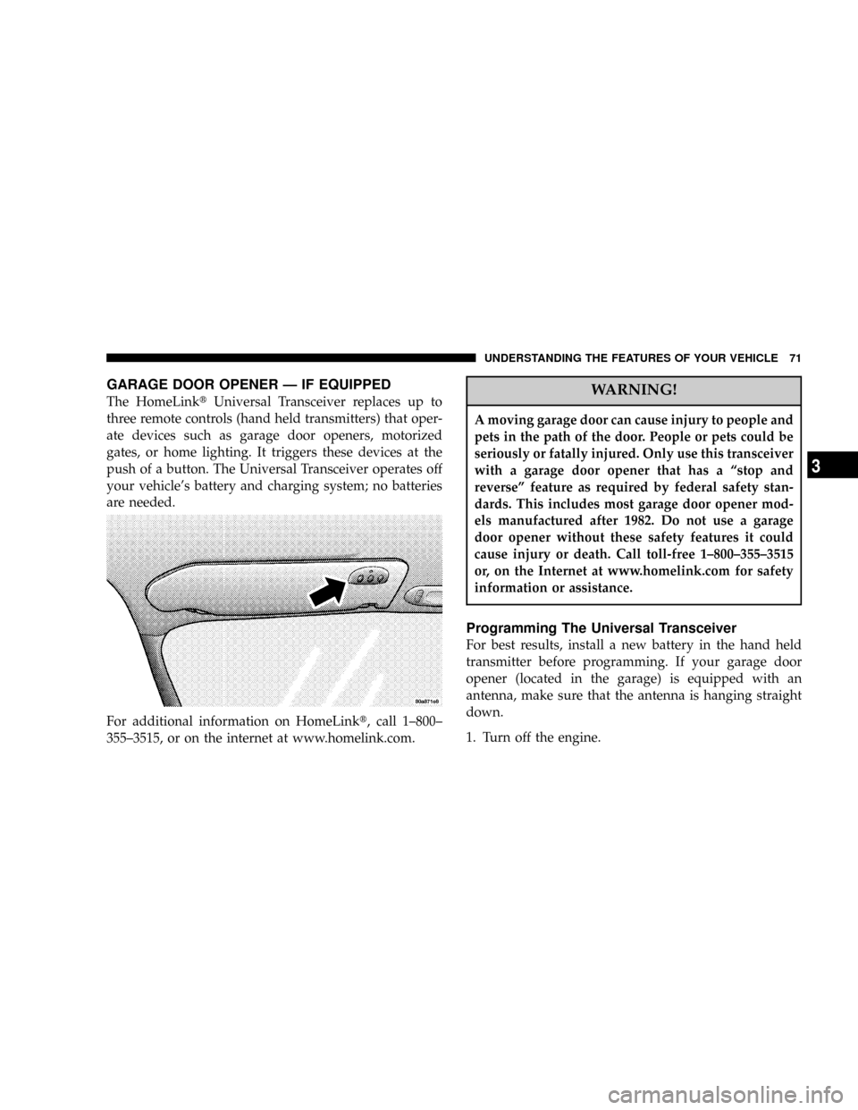
GARAGE DOOR OPENER Ð IF EQUIPPED
The HomeLinktUniversal Transceiver replaces up to
three remote controls (hand held transmitters) that oper-
ate devices such as garage door openers, motorized
gates, or home lighting. It triggers these devices at the
push of a button. The Universal Transceiver operates off
your vehicle's battery and charging system; no batteries
are needed.
For additional information on HomeLinkt, call 1±800±
355±3515, or on the internet at www.homelink.com.WARNING!
A moving garage door can cause injury to people and
pets in the path of the door. People or pets could be
seriously or fatally injured. Only use this transceiver
with a garage door opener that has a ªstop and
reverseº feature as required by federal safety stan-
dards. This includes most garage door opener mod-
els manufactured after 1982. Do not use a garage
door opener without these safety features it could
cause injury or death. Call toll-free 1±800±355±3515
or, on the Internet at www.homelink.com for safety
information or assistance.
Programming The Universal Transceiver
For best results, install a new battery in the hand held
transmitter before programming. If your garage door
opener (located in the garage) is equipped with an
antenna, make sure that the antenna is hanging straight
down.
1. Turn off the engine.
UNDERSTANDING THE FEATURES OF YOUR VEHICLE 71
3
Page 72 of 273
WARNING!
Vehicle exhaust contains carbon monoxide, a danger-
ous gas. Do not run the vehicle's exhaust while
training the transceiver. Exhaust gas can cause seri-
ous injury or death.
WARNING!
Your motorized door or gate will open and close
while you are training the Universal Transceiver. Do
not train the transceiver if people or pets are in the
path of the door or gate. A moving door or gate can
cause serious injury or death to people and pets or
damage to objects.
2. Erase the factory test codes by pressing the two
outside buttons. Release the buttons when the light in the
Universal Transceiver begins to flash (about 20 seconds).
NOTE:Step 2 does not have to be followed to program
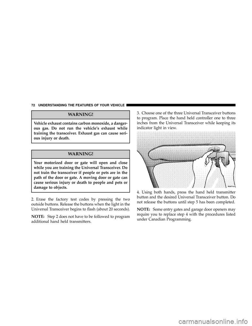
additional hand held transmitters.3. Choose one of the three Universal Transceiver buttons
to program. Place the hand held controller one to three
inches from the Universal Transceiver while keeping its
indicator light in view.
4. Using both hands, press the hand held transmitter
button and the desired Universal Transceiver button. Do
not release the buttons until step 5 has been completed.
NOTE:Some entry gates and garage door openers may
require you to replace step 4 with the procedures listed
under Canadian Programming.
72 UNDERSTANDING THE FEATURES OF YOUR VEHICLE
Page 88 of 273

through several of your typical driving cycles. In most
situations the vehicle will drive normally and will not
require towing.
The Malfunction Indicator Light flashes to alert to serious
conditions that could lead to immediate loss of power or
severe catalytic converter damage. The vehicle should be
serviced as soon as possible if this occurs.
11. Fog Light Indicator Ð If Equipped
This light shows when the fog lights are ON.
12. Temperature Gauge
The temperature gauge shows engine coolant
temperature. Any reading within the normal
range (approximately mid point on the scale)
shows that the cooling system is operating properly.
The gauge pointer may show a higher than normal
temperature when driving in hot weather, up moun-
tain grades, in heavy stop and go traffic, or when
towing a trailer.
If the pointer rises to the ªHº mark, stop the vehicle and
turn off the engine until the problem is corrected.There are steps that you can take to slow down an
impending overheat condition. If your air conditioning is
on, turn it off. The air conditioning system adds heat to
the cooling system and turning off the A/C removes this
heat. You can also turn the Temperature control to
maximum heat, the Mode control to Floor and the Fan
control to High. This allows the heater core to act as a
supplement to the radiator and aids in removing heat
from the cooling system.
13. Engine Temperature Warning Light
This light warns of an overheated engine cool-
ant condition.
14. Transmission Range Indicator
This indicator illuminates to show the automatic trans-
mission gear selection.
An optionalAutoStick Gear Indicatordisplays the current
transaxle gear when in AutoStick mode.
15. Odometer/Trip Odometer
The odometer shows the total distance the vehicle has
been driven.
88 UNDERSTANDING YOUR INSTRUMENT PANEL
Page 89 of 273

U.S. federal regulations require that upon transfer of
vehicle ownership, the seller certify to the purchaser the
correct mileage that the vehicle has been driven. There-
fore, if the odometer reading is changed, during repair or
replacement, be sure to keep a record of the reading
before and after the service so that the correct mileage can
be determined.
The trip odometer shows individual trip mileage. To
switch from odometer to trip odometer, press and release
the Trip Odometer button. Press and release the Trip
button a second time to return to the odometer. While in
trip mode, press and hold the button for at least
1¤2second
to reset the trip odometer.
Door, Deck or Trunk Ajar Warnings
If you move the vehicle and a door is not completely
closed, the word DOOR will replace the odometer dis-
play and a chime will sound once. The odometer display
will reappear when the door is closed. If the trunk is not
completely closed, the work DECK will replace the
odometer display. The odometer display will reappear
when the trunk is closed.
16. Anti-Lock Warning Light Ð If Equipped
This light monitors the Anti-Lock Brake System
described elsewhere in this manual. This light
will come on when the ignition key is turned to the
RUN position and may stay on for several seconds. If
the light does not come on, have the system checked
by an authorized dealer. The warning light should be
checked frequently to assure that it is operating prop-
erly.
If the ABS light remains on or comes on during driving,
it indicates that the Anti-Lock portion of the brake system
is not functioning and that service is required, however,
the conventional brake system will continue to operate
normally provided that the BRAKE warning light is not
on.
17. Oil Pressure Light
Shows low engine oil pressure. The light will
come on and remain on briefly when the igni-
tion is turned on as a bulb check. If the bulb does not
come on during starting, have the bulb repaired
promptly.
UNDERSTANDING YOUR INSTRUMENT PANEL 89
4
Page 90 of 273
If the light comes on and remains on while driving, stop
the vehicle and shut off the engine. Do not operate the
vehicle until the cause is corrected.
The light does not show the quantity of oil in the engine.
This can be determined using the procedure shown in
Section 7.
18. Brake System Warning Light
This light monitors both the brake fluid level
and the parking brake. If the light comes on,
it indicates either that the parking brake is
on or there is a low fluid level in the brake
master cylinder. On vehicles equipped with Anti-lock
brakes (ABS), the brake light may also indicate re-
duced braking performance.
If the parking brake is off and the light remains on, have
the brake system inspected as soon as possible.
WARNING!
Driving a vehicle with the brake light on is danger-
ous. A significant decrease in braking performance
may occur. It will take you longer to stop the vehicle.
You could have an accident. Have the vehicle
checked immediately.
The warning light should be checked frequently to assure
that it is operating properly. Turn the ignition key to the
RUN position. (Refer to ªA Word About Your Keys,
Ignition Key Removalº in this manual for an illustration
of the ignition positions.) The light should come on. If the
light does not come on, have the system checked by an
authorized dealer.
The light will also come on when the parking brake is
applied with the ignition in the RUN position.
NOTE:This light shows only that the parking brake is
on. It does not show the degree of brake application.
90 UNDERSTANDING YOUR INSTRUMENT PANEL
Page 91 of 273

In an ABS equipped vehicle, the Brake System Warning
light will come on if the ABS light is not functioning or if
the ABS system is not communicating.
19. Seat Belt Reminder Light
When the ignition switch is first turned ON, this
light will turn on for 5 to 8 seconds as a bulb
check. During the bulb check, if the driver's seat
belt is unbuckled, a chime will sound. After the bulb
check or when driving, if the driver seat belt remains
unbuckled, the Seat Belt Warning Light will flash or
remain on continuously. Refer to9Enhanced Driver
Seat Belt Reminder System (BeltAlertŸ)9in the Occu-
pant Restraints section for more information.
20. Theft Alarm Light Ð If Equipped
The light in the instrument cluster will flash rapidly for
15 seconds. This shows that the system is arming. If the
light comes on but does not flash, the system is still
armed, but there is a problem in the trunk circuit. After 15
seconds the light will continue to flash slowly. This
shows that the system is fully armed.
21. Low Fuel Light
When the fuel level drops to about 21¤2gallons (91¤2liters), the fuel symbol will light and remain lit
until fuel is added.
COMPASS, TEMPERATURE, AND TRIP
COMPUTER DISPLAY Ð IF EQUIPPED
This feature allows you to choose between a compass /
temperature display and one of five trip conditions being
monitored.
UNDERSTANDING YOUR INSTRUMENT PANEL 91
4
Page 132 of 273
STARTING PROCEDURES
Before starting your vehicle, adjust your seat, adjust both
inside and outside mirrors, and fasten your seat belts.
CAUTION!
Long periods of engine idling, especially at high
engine speeds can cause excessive exhaust tempera-
tures which can damage your vehicle. Do not leave
your vehicle unattended with the engine running.
WARNING!
Do not leave children or animals inside parked
vehicles in hot weather. Interior heat build up may
cause serious injury or death.
Automatic Transaxle
The gear selector must be in the NEUTRAL or PARK
position before you can start the engine. Apply the brakes
before shifting to any driving gear.
Normal Starting
Normal Starting of either a cold or a warm engine does
not require pumping or depressing the accelerator pedal.
Simply turn the key to the ªSTART'º position and release
when the engine starts. If the engine has not started
within 3 seconds, slightly depress the accelerator pedal
while continuing to crank. If the engine fails to start
within 15 seconds, turn the key to the ªOFFº position,
wait 10 to 15 seconds, then repeat the normal starting
procedure.
132 STARTING AND OPERATING
Page 139 of 273
NOTE:Using the ª3º range while operating the vehicle
under heavy operating conditions will improve perfor-
mance, fuel economy, and extend transaxle life by reduc-
ing excessive shifting and heat build up.
Use the ª3º range when descending steep grades to
prevent brake system distress.
ªLº Low
This range should be used for maximum engine braking
when descending steep grades. In this range, up shifts
will occur only to prevent engine over speed while down
shifts occur as early as possible.
WARNING!
Never use Park position on an automatic transmis-
sion as a substitute for the parking brake. Always
apply parking brake fully when parked to guard
against vehicle movement and possible injury or
damage.
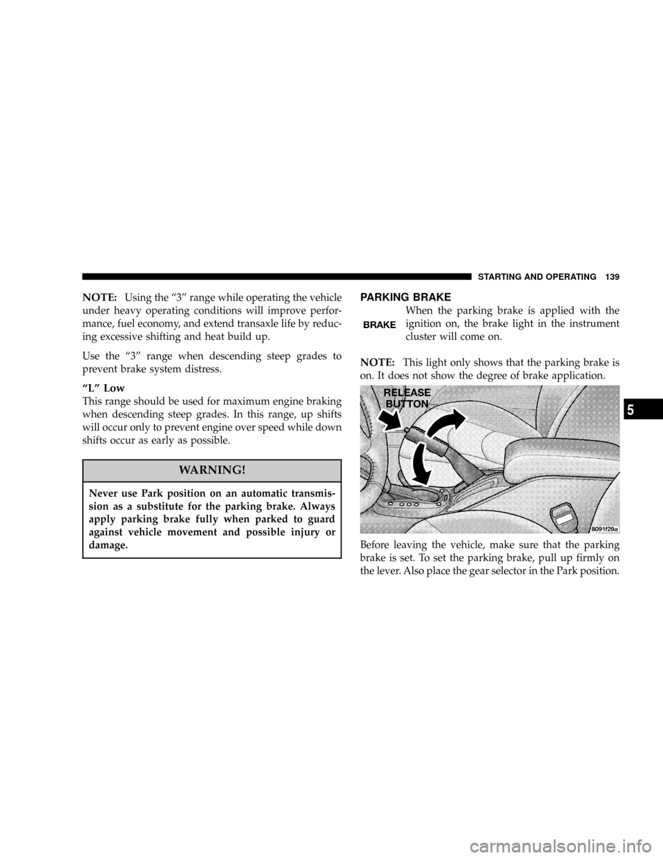
PARKING BRAKE
When the parking brake is applied with the
ignition on, the brake light in the instrument
cluster will come on.
NOTE:This light only shows that the parking brake is
on. It does not show the degree of brake application.
Before leaving the vehicle, make sure that the parking
brake is set. To set the parking brake, pull up firmly on
the lever. Also place the gear selector in the Park position.
STARTING AND OPERATING 139
5
Page 166 of 273

²The weight of any other type of cargo or equipment
put in or on your vehicle.
²Remember that everything put in or on the trailer adds
to the load on your vehicle.
Warranty Requirements
The Manufacturer's Passenger Vehicle Warranty will
apply to vehicles used to tow trailers for non-commercial
use. However the following conditions must be met:
²The maximum trailer load is 1,000 lbs (450 kg).
²The maximum frontal area of the trailer cannot exceed
20 square feet (1.86 square meters).
²If using a manual transaxle vehicle for trailer towing,
all starts must be in FIRST gear to avoid excessive
clutch slippage.
²The trailer tongue load must be considered as part of
the combined weight of occupants and cargo, and
should never exceed the weight referenced on the Tire
and Loading Information placard. Refer to the Tire±
Safety Information Section in this manual.
²The ªDº range can be selected when towing. However,
if frquent shifting occurs while in this range, the ª3º
range must be selected.
NOTE:Using the ª3º range while operating the vehicle
under heavy operating conditions will improve perfor-
mance and extend tranaxle life by reducing excessive
shifting and heat build up.
WARNING!
Connecting trailer brakes to your vehicle's hydraulic
brake lines can overload your brake system and
cause it to fail. You might not have brakes when you
need them and could have an accident.
²Do not attempt to tow a trailer while using a compact
spare tire.
²Whenever you pull a trailer, regardless of the trailer
size, stop lights and turn signals on the trailer are
recommended for motoring safety.
166 STARTING AND OPERATING