service schedule CHRYSLER SEBRING CONVERTIBLE 2008 3.G Owners Manual
[x] Cancel search | Manufacturer: CHRYSLER, Model Year: 2008, Model line: SEBRING CONVERTIBLE, Model: CHRYSLER SEBRING CONVERTIBLE 2008 3.GPages: 454, PDF Size: 5.8 MB
Page 179 of 454

The two trip odometers show individual trip mileage. To
switch from odometer to trip odometers, press and
release the Trip Odometer button. To reset a trip odom-
eter, display the desired trip odometer to be reset then
push and hold the button until the display resets (ap-
proximately 2 seconds). Refer to ªTrip Odometer Buttonº
for additional information.
Vehicle Warning Messages
When the appropriate conditions exist, ªDOOR AJAR,º
ªTRUNK AJAR,º or ªgASCAPº will display in the odom-
eter.
NOTE:If the instrument cluster is equipped with the
optional Electronic Vehicle Information Center (EVIC),
then all warnings including ªDOOR AJARº and
ªTRUNK AJARº will only display in the EVIC. (Refer to
ªElectronic Vehicle Information Center (EVIC)º in this
section for specific messages).gASCAP
If the vehicle diagnostic system detects a leak or change
in the evaporative system, or the fuel filler cap is loose,
improperly installed, or damaged, the words ªgASCAPº
will display in the odometer. If this occurs, tighten the
fuel filler cap properly and press the odometer reset
button to turn off the ªgASCAPº message. (Refer to
ªOnboard Diagnostic System Ð OBDIIº in Section 7 of
this manual for more information). If the problem con-
tinues, the message will appear the next time the vehicle
is started. See your authorized dealer service center as
soon as possible.
Change Oil
Your vehicle is equipped with an engine oil change
indicator system. The ªChange Oilº message will flash in
the instrument cluster odometer for approximately 12
seconds after a single chime has sounded to indicate the
next scheduled oil change interval. The engine oil change
UNDERSTANDING YOUR INSTRUMENT PANEL 179
4
Page 244 of 454

Window Fogging
Interior fogging on the windshield can be quickly re-
moved by turning the mode selector to Defrost. The
Defrost/Floor mode can be used to maintain a clear
windshield and provide sufficient heating. If side win-
dow fogging becomes a problem, increase blower speed.
Vehicle windows tend to fog on the inside in mild but
rainy or humid weather.
NOTE:Recirculate without A/C should not be used for
long periods as fogging may occur.
Side Window Demisters
A side window demister outlet is located at each end of
the instrument panel. These non-adjustable outlets direct
air toward the side windows when the system is in the
FLOOR, MIX, or DEFROST mode. The air is directed at
the area of the windows through which you view the
outside mirrors.
Outside Air Intake
Make sure the air intake, located directly in front of the
windshield, is free of obstructions such as leaves. Leaves
collected in the air intake may reduce airflow, and if they
enter the plenum, they could plug the water drains. In
winter months, make sure the air intake is clear of ice,
slush, and snow.
A/C Air Filter Ð If Equipped
The A/C Air Filter will reduce, but not eliminate, diesel
and agricultural smells. The filter acts on air coming from
outside the vehicle and recirculated air within the pas-
senger compartment. Refer to ªMaintenance Proceduresº
in Section 7 of this manual for A/C Air Filter service
information or see your authorized dealer for service.
Refer to the ªMaintenance Schedulesº in Section 8 of this
manual for filter service intervals.
244 UNDERSTANDING YOUR INSTRUMENT PANEL
Page 360 of 454
vehicle serviced before going to the I/M station. The I/M
station can fail your vehicle because the MIL symbol is on
with the engine running.
REPLACEMENT PARTS
Use of genuine Mopartparts for normal/scheduled
maintenance and repairs is highly recommended to en-
sure the designed performance. Damage or failures
caused by the use of non-Mopartparts for maintenance
and repairs will not be covered by the manufacturer's
warranty.
DEALER SERVICE
Your authorized dealer has the qualified service person-
nel, special tools, and equipment to perform all service
operations in an expert manner. Service Manuals are
available which include detailed service information for
your vehicle. Refer to these manuals before attempting
any procedure yourself.NOTE:Intentional tampering with emissions control
systems can result in civil penalties being assessed
against you.
WARNING!
You can be badly injured working on or around a
motor vehicle. Only do service work for which you
have the knowledge and the proper equipment. If
you have any doubt about your ability to perform a
service job, take your vehicle to a competent
mechanic.
360 MAINTAINING YOUR VEHICLE
Page 365 of 454

Engine Oil Filter
The engine oil filter should be replaced at every engine
oil change.
Engine Oil Filter Selection
All of this manufacturer's engines have a full-flow type
disposable oil filter. Use a filter of this type for replace-
ment. The quality of replacement filters varies consider-
ably. Only high quality filters should be used to assure
most efficient service. MopartEngine Oil Filters are high
quality oil filters and are recommended.
Drive Belt
At the mileage indicated in section 8: ªMaintenance
Scheduleº, replace the drive belt with a new drive belt.
NOTE:The belt must be routed correctly to ensure
proper drive function.
Spark Plugs
Spark plugs must fire properly to assure engine perfor-
mance and emission control. New plugs should be in-
stalled at the specified mileage. The entire set should be
replaced if there is any malfunction due to a faulty spark
plug. Refer to ªFluids, Lubricants, and Genuine Partsº in
this section for the proper type of spark plug for use in
your vehicle.
Engine Air Cleaner Filter
Refer to the ªMaintenance Scheduleº in Section 8 of this
manual for engine air cleaner filter maintenance inter-
vals.
NOTE:Be sure to follow the ªdusty or off-road condi-
tionsº maintenance interval if applicable.
MAINTAINING YOUR VEHICLE 365
7
Page 370 of 454
Refrigerant Recovery and Recycling
R-134a Air Conditioning Refrigerant is a hydrofluorocar-
bon (HFC) that is endorsed by the Environmental Pro-
tection Agency and is an ozone-saving product. How-
ever, the manufacturer recommends that air conditioning
service be performed by dealers or other service facilities
using recovery and recycling equipment.
NOTE:Use only manufacturer approved A/C System
Sealers, Stop Leak Products, Seal Conditioners, Compres-
sor Oil, and Refrigerants.
A/C Air Filter Ð If Equipped
Refer to the ªMaintenance Scheduleº in Section 8 of this
manual for A/C Air Filter service intervals.
WARNING!
Do not remove the A/C Air Filter while the blower is
operating or personal injury may result.The A/C Air Filter is located in the fresh air inlet behind
the glove box. Perform the following procedure to re-
place the filter:
1. Open the glove box and remove all contents.
2. Push in on the sides of the glove box and lower the
door.
3. Disconnect the glove box door dampener from the slot
on the side of the box. This is done by grasping the
dampener connector (on the outside of the box) and the
end of the connector pin (on the inside of the box) with
your thumb and forefinger and pulling outward while
lightly lifting upward on the door with your other hand.
Once disconnected, the dampener will retract under-
neath the instrument panel if you release it.
4. Pivot the glove box downward.
370 MAINTAINING YOUR VEHICLE
Page 381 of 454

Hoses and Vacuum/Vapor Harnesses
Inspect surfaces of hoses and nylon tubing for evidence
of heat and mechanical damage. Hard or soft spots,
brittle rubber, cracking, tears, cuts, abrasions, and exces-
sive swelling indicate deterioration of the rubber
Pay particular attention to the hoses nearest to high heat
sources such as the exhaust manifold. Inspect hose rout-
ing to be sure hoses do not touch any heat source or
moving component that may cause heat damage or
mechanical wear.
Insure nylon tubing in these areas has not melted or
collapsed
Inspect all hose connections such as clamps and cou-
plings to make sure they are secure and no leaks are
present.
Components should be replaced immediately if there is
any evidence of degradation that could cause failure.
Fuel System
Electronic Fuel Injection high-pressure fuel systems are
designed with tubes and special connects, connections,
and clamps which have unique material characteristics to
provide adequate sealing and resist attack by deterio-
rated gasoline.
You are urged to use only the manufactures-specified
tubes, connections and clamps, or their equivalent in
material and specification, in any fuel system servicing.
Brake System
In order to assure brake system performance, all brake
system components should be inspected periodically.
Suggested service intervals can be found in the ªMainte-
nance Scheduleº in this manual.
MAINTAINING YOUR VEHICLE 381
7
Page 382 of 454
WARNING!
Riding the brakes can lead to brake failure and
possibly an accident. Driving with your foot resting
or riding on the brake pedal can result in abnormally
high brake temperatures, excessive lining wear, and
possible brake damage. You wouldn't have your full
braking capacity in an emergency.
Brake And Power Steering Hoses
When servicing the vehicle for scheduled maintenance,
inspect the surface of the hoses and nylon tubing for
evidence of heat and mechanical damage. Hard and brittle
rubber, cracking, tears, cuts, abrasions, and excessive swell-
ing suggest deterioration of the rubber. Particular attention
should be made to examining those hose surfaces nearest
to high heat sources, such as the exhaust manifold.
Insure nylon tubing in these areas has not melted or
collapsed.Inspect all hose clamps and couplings to make sure they
are secure and no leaks are present.
NOTE:
²Often, fluids such as oil, power steering fluid, and
brake fluid are used during assembly plant operations
to ease the assembly of hoses to couplings. Therefore,
oil wetness at the hose-coupling area is not necessarily
an indication of leakage. Actual dripping of hot fluid
when systems are under pressure (during vehicle
operation) should be noted before a hose is replaced
based on leakage.
²Inspect the brake hoses whenever the brake system is
serviced and at every engine oil change. Inspect hy-
draulic brake hoses for surface cracking, scuffing, or
worn spots. If there is any evidence of cracking,
scuffing, or worn spots, the hose should be replaced
immediately! Eventual deterioration of the hose can
take place resulting in a possibility of a burst failure.
382 MAINTAINING YOUR VEHICLE
Page 414 of 454
EMISSION CONTROL SYSTEM MAINTENANCE
The ªScheduledº maintenance services, listed inbold
typemust be done at the times or mileages specified to
assure the continued proper functioning of the emission
control system. These, and all other maintenance services
included in this manual, should be done to provide best
vehicle performance and reliability. More frequent main-
tenance may be needed for vehicles in severe operating
conditions such as dusty areas and very short trip
driving.
Inspection and service also should be done anytime a
malfunction is suspected.
NOTE:Maintenance, replacement, or repair of the emis-
sion control devices and systems on your vehicle may be
performed by any automotive repair establishment or
individual using any automotive part, which has been
certified pursuant to U.S. EPA or, in the State of Califor-
nia, California Air Resources Board regulations.
MAINTENANCE SCHEDULE
The oil change indicator system will remind you that it is
time to take your vehicle in for scheduled maintenance.
On Electronic Vehicle Information Center (EVIC)
equipped vehicles ªOil Change Requiredº will be dis-
played in the EVIC and a single chime will sound,
indicating that an oil change is necessary.
On Non-EVIC equipped vehicles ªChange Oilº will flash
in the instrument cluster odometer and a single chime
will sound, indicating that an oil change is necessary.
Based on engine operation conditions the oil change
indicator message will illuminate, this means that service
is required for your vehicle. Have your vehicle serviced
as soon as possible, within the next 500 miles (805 km).
414 MAINTENANCE SCHEDULES
8
M
A
I
N
T
E
N
A
N
C
E
S
C
H
E
D
U
L
E
S
Page 416 of 454
Once a Month
²Check tire pressure and look for unusual wear or
damage.
²Inspect the battery and clean and tighten the terminals
as required.
²Check the fluid levels of coolant reservoir, brake
master cylinder, power steering, and automatic trans-
axle, and add fluid as needed.
NOTE:Six speed AutoSticktTransaxle Ð if equipped is
sealed, therefore checking the fluid level can only be
done by a certified dealership service center.
²Check all lights and other electrical items for correct
operation.At Each Oil Change
²Change the engine oil filter.
²Inspect the brake hoses and lines.
CAUTION!
Failure to perform the required maintenance items
may result in damage to the vehicle.
416 MAINTENANCE SCHEDULES
8
M
A
I
N
T
E
N
A
N
C
E
S
C
H
E
D
U
L
E
S
Page 419 of 454
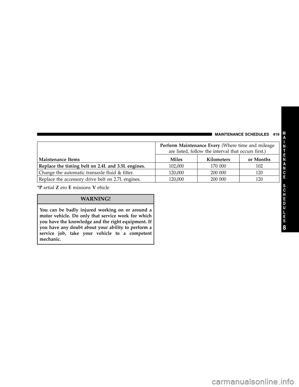
Perform Maintenance Every(Where time and mileage
are listed, follow the interval that occurs first.)
Maintenance Items Miles Kilometers or Months
Replace the timing belt on 2.4L and 3.5L engines.102,000 170 000 102
Change the automatic transaxle fluid & filter. 120,000 200 000 120
Replace the accessory drive belt on 2.7L engines. 120,000 200 000 120
*PartialZeroEmissionsVehicle
WARNING!
You can be badly injured working on or around a
motor vehicle. Do only that service work for which
you have the knowledge and the right equipment. If
you have any doubt about your ability to perform a
service job, take your vehicle to a competent
mechanic.
MAINTENANCE SCHEDULES 419
8
M
A
I
N
T
E
N
A
N
C
E
S
C
H
E
D
U
L
E
S