battery location CHRYSLER TOWN AND COUNTRY 2002 Service Manual
[x] Cancel search | Manufacturer: CHRYSLER, Model Year: 2002, Model line: TOWN AND COUNTRY, Model: CHRYSLER TOWN AND COUNTRY 2002Pages: 2399, PDF Size: 57.96 MB
Page 2277 of 2399
(3) See the fuse and relay layout map molded into
the inner surface of the IPM cover for rear blower
motor relay identification and location.
(4) Remove the rear blower motor relay from the
IPM.
INSTALLATION
(1) See the fuse and relay layout map molded into
the inner surface of the Intelligent Power Module
(IPM) cover for rear blower motor relay identification
and location.
(2) Position the rear blower motor relay to the
proper receptacle in the IPM.
(3) Align the rear blower motor relay terminals
with the terminal cavities in the IPM relay recepta-
cle.
(4) Push down firmly on the rear blower motor
relay until the terminals are fully seated in the ter-
minal cavities in the IPM receptacle.
(5) Install and latch the cover onto the IPM.
(6) Reconnect the battery negative cable.
BLOWER MOTOR RESISTOR
DESCRIPTION
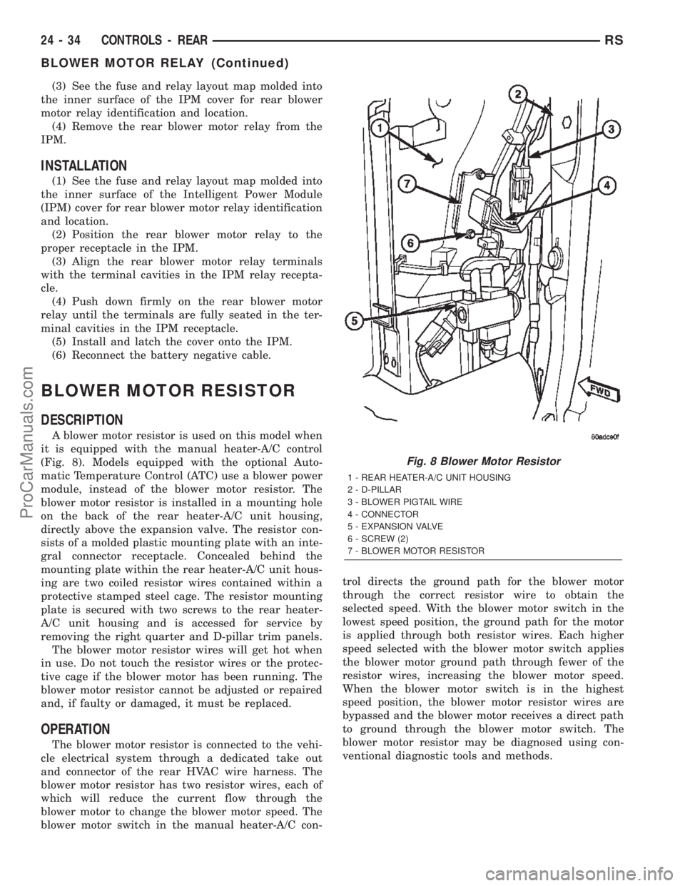
A blower motor resistor is used on this model when
it is equipped with the manual heater-A/C control
(Fig. 8). Models equipped with the optional Auto-
matic Temperature Control (ATC) use a blower power
module, instead of the blower motor resistor. The
blower motor resistor is installed in a mounting hole
on the back of the rear heater-A/C unit housing,
directly above the expansion valve. The resistor con-
sists of a molded plastic mounting plate with an inte-
gral connector receptacle. Concealed behind the
mounting plate within the rear heater-A/C unit hous-
ing are two coiled resistor wires contained within a
protective stamped steel cage. The resistor mounting
plate is secured with two screws to the rear heater-
A/C unit housing and is accessed for service by
removing the right quarter and D-pillar trim panels.
The blower motor resistor wires will get hot when
in use. Do not touch the resistor wires or the protec-
tive cage if the blower motor has been running. The
blower motor resistor cannot be adjusted or repaired
and, if faulty or damaged, it must be replaced.
OPERATION
The blower motor resistor is connected to the vehi-
cle electrical system through a dedicated take out
and connector of the rear HVAC wire harness. The
blower motor resistor has two resistor wires, each of
which will reduce the current flow through the
blower motor to change the blower motor speed. The
blower motor switch in the manual heater-A/C con-trol directs the ground path for the blower motor
through the correct resistor wire to obtain the
selected speed. With the blower motor switch in the
lowest speed position, the ground path for the motor
is applied through both resistor wires. Each higher
speed selected with the blower motor switch applies
the blower motor ground path through fewer of the
resistor wires, increasing the blower motor speed.
When the blower motor switch is in the highest
speed position, the blower motor resistor wires are
bypassed and the blower motor receives a direct path
to ground through the blower motor switch. The
blower motor resistor may be diagnosed using con-
ventional diagnostic tools and methods.
Fig. 8 Blower Motor Resistor
1 - REAR HEATER-A/C UNIT HOUSING
2 - D-PILLAR
3 - BLOWER PIGTAIL WIRE
4 - CONNECTOR
5 - EXPANSION VALVE
6 - SCREW (2)
7 - BLOWER MOTOR RESISTOR
24 - 34 CONTROLS - REARRS
BLOWER MOTOR RELAY (Continued)
ProCarManuals.com
Page 2278 of 2399
DIAGNOSIS AND TESTING - BLOWER MOTOR
RESISTOR
Refer to the appropriate wiring information. The
wiring information includes wiring diagrams, proper
wire and connector repair procedures, details of wire
harness routing and retention, connector pin-out
information and location views for the various wire
harness connectors, splices and grounds.
(1) Disconnect and isolate the battery negative
cable.
(2) Disconnect the rear HVAC wire harness con-
nector for the blower motor resistor from the resistor
connector receptacle.
(3) Check for continuity between each of the
blower motor switch input terminals of the blower
motor resistor and the resistor output terminal. In
each case there should be continuity. If OK, repair
the wire harness circuits between the blower motor
switch and the blower motor resistor or the blower
motor pigtail wires as required. If not OK, replace
the faulty blower motor resistor.
REMOVAL
WARNING: THE BLOWER MOTOR RESISTOR MAY
GET VERY HOT DURING NORMAL OPERATION. IF
THE BLOWER MOTOR WAS TURNED ON, WAIT
FIVE MINUTES TO ALLOW THE BLOWER MOTOR
RESISTOR TO COOL BEFORE PERFORMING DIAG-
NOSIS OR SERVICE. FAILURE TO TAKE THIS PRE-
CAUTION CAN RESULT IN PERSONAL INJURY.
CAUTION: Do not operate the blower motor with the
blower motor resistor removed from the circuit.
Failure to take this precaution can result in vehicle
damage.
(1) Disconnect and isolate the battery negative
cable.
(2) Remove the right quarter trim panel and right
D-pillar trim panel from the quarter inner panel.
(Refer to 23 - BODY/INTERIOR/QUARTER TRIM
PANEL - REMOVAL).
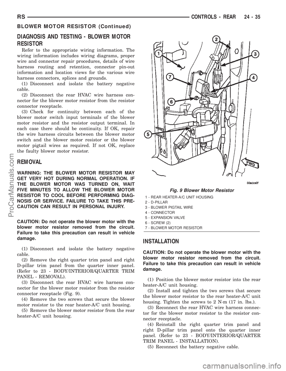
(3) Disconnect the rear HVAC wire harness con-
nector for the blower motor resistor from the resistor
connector receptacle (Fig. 9).
(4) Remove the two screws that secure the blower
motor resistor to the rear heater-A/C unit housing.
(5) Remove the blower motor resistor from the rear
heater-A/C unit housing.
INSTALLATION
CAUTION: Do not operate the blower motor with the
blower motor resistor removed from the circuit.
Failure to take this precaution can result in vehicle
damage.
(1) Position the blower motor resistor into the rear
heater-A/C unit housing.
(2) Install and tighten the two screws that secure
the blower motor resistor to the rear heater-A/C unit
housing. Tighten the screws to 2 N´m (17 in. lbs.).
(3) Reconnect the rear HVAC wire harness connec-
tor for the blower motor resistor to the resistor con-
nector receptacle.
(4) Reinstall the right quarter trim panel and
right D-pillar trim panel onto the quarter inner
panel. (Refer to 23 - BODY/INTERIOR/QUARTER
TRIM PANEL - INSTALLATION).
(5) Reconnect the battery negative cable.
Fig. 9 Blower Motor Resistor
1 - REAR HEATER-A/C UNIT HOUSING
2 - D-PILLAR
3 - BLOWER PIGTAIL WIRE
4 - CONNECTOR
5 - EXPANSION VALVE
6 - SCREW (2)
7 - BLOWER MOTOR RESISTOR
RSCONTROLS - REAR24-35
BLOWER MOTOR RESISTOR (Continued)
ProCarManuals.com
Page 2290 of 2399
(4) Position the upper pivot of the recirculation
door into the opening at the top of the air inlet hous-
ing an dhold in place while the lower air inlet hous-
ing is placed in position.
(5) Install and tighten the three screws (from the
bottom) that secure the lower air intake housing to
the lower half of the evaporator housing. Tighten the
screws to 2 N´m (18 in. lbs.).
(6) Install and tighten the one screw that secures
the upper intake air housing to the lower intake air
housing. Tighten the screws to 2 N´m (18 in. lbs.).
(7) Install the recirculation actuator making cer-
tain that the splines are aligned and secure the
actuator with two screws and torque the to 2 N´m (18
in. lbs.). Route the wiring into the molded inn rout-
ing clips.
(8) Position the carpet into location and install the
lower right trim panel.
(9) Connect the blower motor pigtail wire harness
electrical connector back into either the power mod-
ule or resistor receptacle.
(10) Run the Heater-A/C Calibration procedure(Re-
fer to 24 - HEATING & AIR CONDITIONING/CON-
TROLS/A/C HEATER CONTROL - STANDARD
PROCEDURE).
(11) Run the HVAC Control Cooldown test(Refer to
24 - HEATING & AIR CONDITIONING - DIAGNO-
SIS AND TESTING).
DEFROSTER DUCT
REMOVAL
WARNING: ON VEHICLES EQUIPPED WITH AIR-
BAGS, DISABLE THE AIRBAG SYSTEM BEFORE
ATTEMPTING ANY STEERING WHEEL, STEERING
COLUMN, OR INSTRUMENT PANEL COMPONENT
DIAGNOSIS OR SERVICE. DISCONNECT AND ISO-
LATE THE BATTERY NEGATIVE (GROUND) CABLE,
THEN WAIT TWO MINUTES FOR THE AIRBAG SYS-
TEM CAPACITOR TO DISCHARGE BEFORE PER-
FORMING FURTHER DIAGNOSIS OR SERVICE. THIS
IS THE ONLY SURE WAY TO DISABLE THE AIRBAG
SYSTEM. FAILURE TO TAKE THE PROPER PRE-
CAUTIONS COULD RESULT IN ACCIDENTAL AIR-
BAG DEPLOYMENT AND POSSIBLE PERSONAL
INJURY.
(1) Disconnect and isolate the battery negative
cable.
(2) Remove the instrument panel from the vehicle.
(Refer to 23 - BODY/INSTRUMENT PANEL/IN-
STRUMENT PANEL ASSEMBLY - REMOVAL).
(3) Place the instrument panel face down on a
suitable work surface. Be certain to take the properprecautions to protect the face of the instrument
panel from cosmetic damage.
(4) Remove the fasteners that secure the defroster
duct to the instrument panel armature.
(5) Remove the defroster duct from the instrument
panel.
INSTALLATION
WARNING: ON VEHICLES EQUIPPED WITH AIR-
BAGS, DISABLE THE AIRBAG SYSTEM BEFORE
ATTEMPTING ANY STEERING WHEEL, STEERING
COLUMN, OR INSTRUMENT PANEL COMPONENT
DIAGNOSIS OR SERVICE. DISCONNECT AND ISO-
LATE THE BATTERY NEGATIVE (GROUND) CABLE,
THEN WAIT TWO MINUTES FOR THE AIRBAG SYS-
TEM CAPACITOR TO DISCHARGE BEFORE PER-
FORMING FURTHER DIAGNOSIS OR SERVICE. THIS
IS THE ONLY SURE WAY TO DISABLE THE AIRBAG
SYSTEM. FAILURE TO TAKE THE PROPER PRE-
CAUTIONS COULD RESULT IN ACCIDENTAL AIR-
BAG DEPLOYMENT AND POSSIBLE PERSONAL
INJURY.
(1) Position the defroster duct to the instrument
panel.
(2) Install the fasteners that secure the defroster
duct to the instrument panel armature.
(3) Reinstall the instrument panel in the vehicle.
(Refer to 23 - BODY/INSTRUMENT PANEL/IN-
STRUMENT PANEL ASSEMBLY - INSTALLA-
TION).
(4) Reconnect the battery negative cable.
DEMISTER DUCTS
REMOVAL
WARNING: ON VEHICLES EQUIPPED WITH AIR-
BAGS, DISABLE THE AIRBAG SYSTEM BEFORE
ATTEMPTING ANY STEERING WHEEL, STEERING
COLUMN, OR INSTRUMENT PANEL COMPONENT
DIAGNOSIS OR SERVICE. DISCONNECT AND ISO-
LATE THE BATTERY NEGATIVE (GROUND) CABLE,
THEN WAIT TWO MINUTES FOR THE AIRBAG SYS-
TEM CAPACITOR TO DISCHARGE BEFORE PER-
FORMING FURTHER DIAGNOSIS OR SERVICE. THIS
IS THE ONLY SURE WAY TO DISABLE THE AIRBAG
SYSTEM. FAILURE TO TAKE THE PROPER PRE-
CAUTIONS COULD RESULT IN ACCIDENTAL AIR-
BAG DEPLOYMENT AND POSSIBLE PERSONAL
INJURY.
(1) Disconnect and isolate the battery negative
cable.
RSDISTRIBUTION - FRONT24-47
BLOWER MOTOR (Continued)
ProCarManuals.com
Page 2317 of 2399
REMOVAL
REMOVAL- HEATER CORE EXTENSION TUBES
WARNING: REFER TO THE APPLICABLE WARN-
INGS AND CAUTIONS FOR THIS SYSTEM BEFORE
PERFORMING THE FOLLOWING OPERATION.
(Refer to 24 - HEATING & AIR CONDITIONING/
PLUMBING FRONT - WARNING - HEATER PLUMB-
ING).
WARNING: ON VEHICLES EQUIPPED WITH AIR-
BAGS, DISABLE THE AIRBAG SYSTEM BEFORE
ATTEMPTING ANY STEERING WHEEL, STEERING
COLUMN, OR INSTRUMENT PANEL COMPONENT
DIAGNOSIS OR SERVICE. DISCONNECT AND ISO-
LATE THE BATTERY NEGATIVE (GROUND) CABLE,
THEN WAIT TWO MINUTES FOR THE AIRBAG SYS-
TEM CAPACITOR TO DISCHARGE BEFORE PER-
FORMING FURTHER DIAGNOSIS OR SERVICE. THIS
IS THE ONLY SURE WAY TO DISABLE THE AIRBAG
SYSTEM. FAILURE TO TAKE THE PROPER PRE-
CAUTIONS COULD RESULT IN ACCIDENTAL AIR-
BAG DEPLOYMENT AND POSSIBLE PERSONAL
INJURY.
(1) Drain the engine cooling system. (Refer to 7 -
COOLING - STANDARD PROCEDURE - COOLING
SYSTEM DRAIN).
(2) Disconnect and isolate the battery negative
cable.
(3) Disconnect the heater hoses from the heater
hose tubes. (Refer to 24 - HEATING & AIR CONDI-
TIONING/PLUMBING - FRONT/HEATER HOSE -
REMOVAL).
(4) Remove the silencer from beneath the driver
side end of the instrument panel. (Refer to 23 -
BODY/INSTRUMENT PANEL/INSTRUMENT
PANEL SILENCER - REMOVAL).
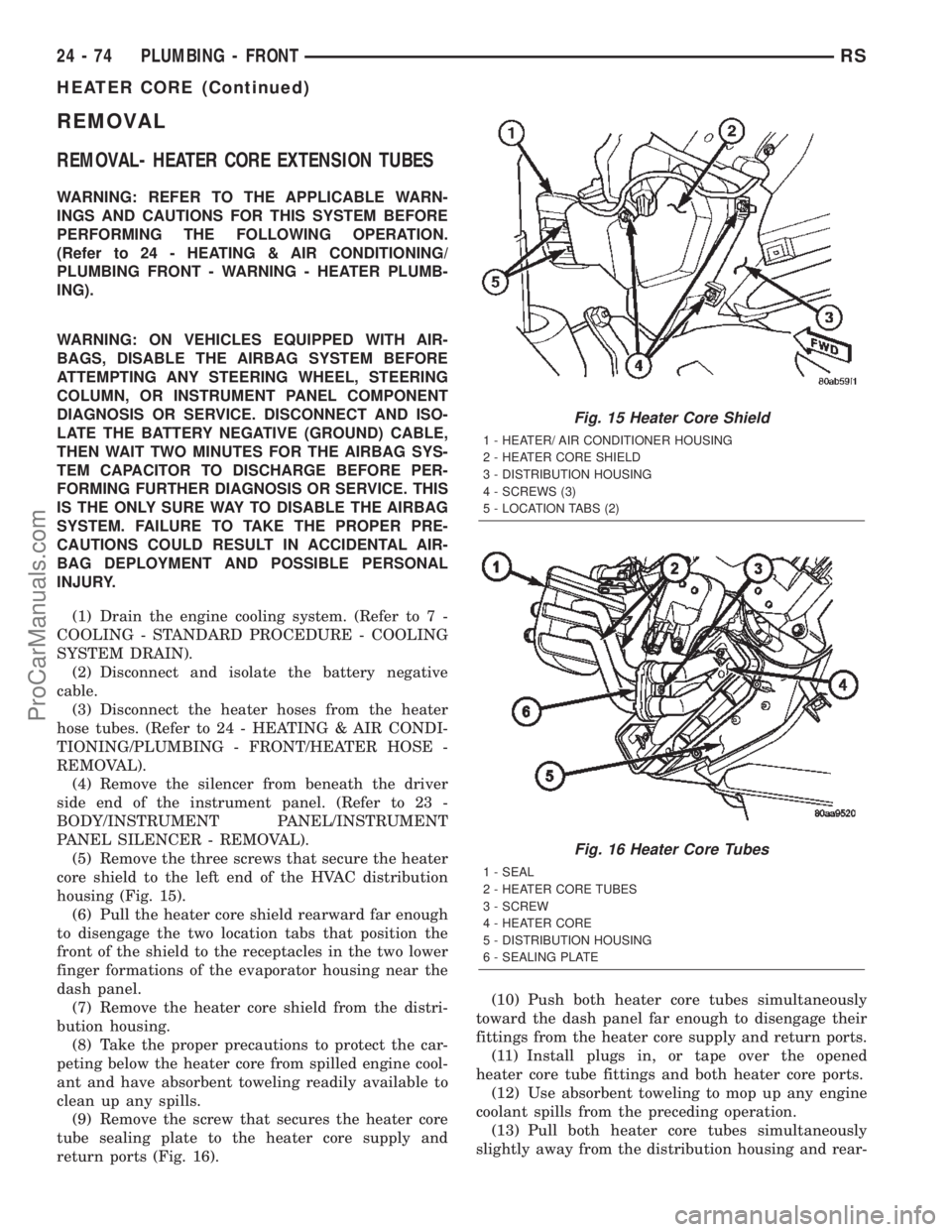
(5) Remove the three screws that secure the heater
core shield to the left end of the HVAC distribution
housing (Fig. 15).
(6) Pull the heater core shield rearward far enough
to disengage the two location tabs that position the
front of the shield to the receptacles in the two lower
finger formations of the evaporator housing near the
dash panel.
(7) Remove the heater core shield from the distri-
bution housing.
(8) Take the proper precautions to protect the car-
peting below the heater core from spilled engine cool-
ant and have absorbent toweling readily available to
clean up any spills.
(9) Remove the screw that secures the heater core
tube sealing plate to the heater core supply and
return ports (Fig. 16).(10) Push both heater core tubes simultaneously
toward the dash panel far enough to disengage their
fittings from the heater core supply and return ports.
(11) Install plugs in, or tape over the opened
heater core tube fittings and both heater core ports.
(12) Use absorbent toweling to mop up any engine
coolant spills from the preceding operation.
(13) Pull both heater core tubes simultaneously
slightly away from the distribution housing and rear-
Fig. 15 Heater Core Shield
1 - HEATER/ AIR CONDITIONER HOUSING
2 - HEATER CORE SHIELD
3 - DISTRIBUTION HOUSING
4 - SCREWS (3)
5 - LOCATION TABS (2)
Fig. 16 Heater Core Tubes
1 - SEAL
2 - HEATER CORE TUBES
3 - SCREW
4 - HEATER CORE
5 - DISTRIBUTION HOUSING
6 - SEALING PLATE
24 - 74 PLUMBING - FRONTRS
HEATER CORE (Continued)
ProCarManuals.com
Page 2318 of 2399
ward far enough to disengage the engine compart-
ment ends of the tubes from the dash panel seal.
(14) Remove the heater core tubes and sealing
plate as a unit from beneath the instrument panel.
(15) Use absorbent toweling to clean up any
engine coolant spills from the preceding operation.
REMOVAL - HEATER CORE
WARNING: REFER TO THE APPLICABLE WARN-
INGS AND CAUTIONS FOR THIS SYSTEM BEFORE
PERFORMING THE FOLLOWING OPERATION.
(Refer to 24 - HEATING & AIR CONDITIONING/
PLUMBING FRONT - WARNING - HEATER PLUMB-
ING).
WARNING: ON VEHICLES EQUIPPED WITH AIR-
BAGS, DISABLE THE AIRBAG SYSTEM BEFORE
ATTEMPTING ANY STEERING WHEEL, STEERING
COLUMN, OR INSTRUMENT PANEL COMPONENT
DIAGNOSIS OR SERVICE. DISCONNECT AND ISO-
LATE THE BATTERY NEGATIVE (GROUND) CABLE,
THEN WAIT TWO MINUTES FOR THE AIRBAG SYS-
TEM CAPACITOR TO DISCHARGE BEFORE PER-
FORMING FURTHER DIAGNOSIS OR SERVICE. THIS
IS THE ONLY SURE WAY TO DISABLE THE AIRBAG
SYSTEM. FAILURE TO TAKE THE PROPER PRE-
CAUTIONS COULD RESULT IN ACCIDENTAL AIR-
BAG DEPLOYMENT AND POSSIBLE PERSONAL
INJURY.
(1) Drain the engine cooling system. (Refer to 7 -
COOLING - STANDARD PROCEDURE - COOLING
SYSTEM DRAIN).
(2) Disconnect and isolate the battery negative
cable.
(3) Remove the silencer boot fasteners located
around the base of the lower steering shaft from the
dash panel so that it may be pushed aside.
(4) Remove the brake lamp switch from its mount-
ing bracket. (Refer to 8 - ELECTRICAL/LAMPS/
LIGHTING - EXTERIOR/BRAKE LAMP SWITCH -
REMOVAL).
(5) Disconnect the power brake booster input rod
(push rod) from the pin on the brake pedal arm.
(Refer to 5 - BRAKES - ABS/HYDRAULIC/ME-
CHANICAL/POWER BRAKE BOOSTER - REMOV-
AL).
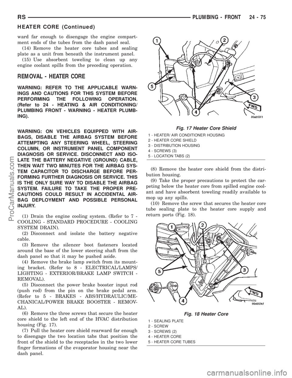
(6) Remove the three screws that secure the heater
core shield to the left end of the HVAC distribution
housing (Fig. 17).
(7) Pull the heater core shield rearward far enough
to disengage the two location tabs that position the
front of the shield to the receptacles in the two lower
finger formations of the evaporator housing near the
dash panel.(8) Remove the heater core shield from the distri-
bution housing.
(9) Take the proper precautions to protect the car-
peting below the heater core from spilled engine cool-
ant and have absorbent toweling readily available to
mop up any spills.
(10) Remove the screw that secures the heater core
tube sealing plate to the heater core supply and
return ports (Fig. 18).
Fig. 17 Heater Core Shield
1 - HEATER/ AIR CONDITIONER HOUSING
2 - HEATER CORE SHIELD
3 - DISTRIBUTION HOUSING
4 - SCREWS (3)
5 - LOCATION TABS (2)
Fig. 18 Heater Core
1 - SEALING PLATE
2 - SCREW
3 - SCREWS (2)
4 - HEATER CORE
5 - HEATER CORE TUBES
RSPLUMBING - FRONT24-75
HEATER CORE (Continued)
ProCarManuals.com
Page 2319 of 2399
(11) Push both heater core tubes simultaneously
toward the dash panel far enough to disengage their
fittings from the heater core supply and return ports.
(12) Install plugs in, or tape over the opened
heater core tube fittings and both heater core ports.
(13) Use absorbent toweling to mop up any engine
coolant spills from the preceding operation.
(14) Remove the two screws that secure the heater
core mounting plate to the distribution housing.
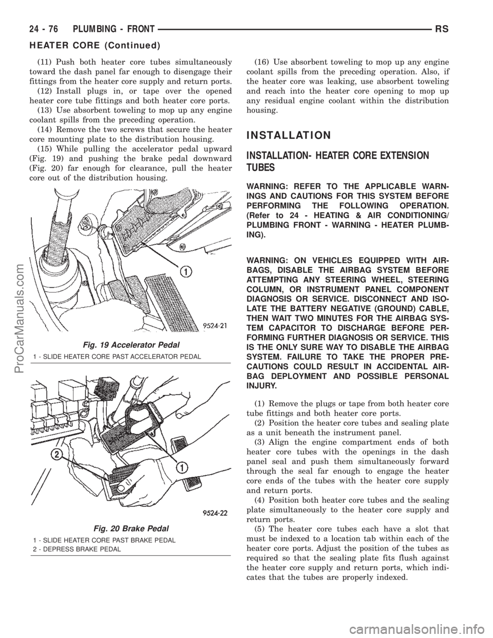
(15) While pulling the accelerator pedal upward
(Fig. 19) and pushing the brake pedal downward
(Fig. 20) far enough for clearance, pull the heater
core out of the distribution housing.(16) Use absorbent toweling to mop up any engine
coolant spills from the preceding operation. Also, if
the heater core was leaking, use absorbent toweling
and reach into the heater core opening to mop up
any residual engine coolant within the distribution
housing.
INSTALLATION
INSTALLATION- HEATER CORE EXTENSION
TUBES
WARNING: REFER TO THE APPLICABLE WARN-
INGS AND CAUTIONS FOR THIS SYSTEM BEFORE
PERFORMING THE FOLLOWING OPERATION.
(Refer to 24 - HEATING & AIR CONDITIONING/
PLUMBING FRONT - WARNING - HEATER PLUMB-
ING).
WARNING: ON VEHICLES EQUIPPED WITH AIR-
BAGS, DISABLE THE AIRBAG SYSTEM BEFORE
ATTEMPTING ANY STEERING WHEEL, STEERING
COLUMN, OR INSTRUMENT PANEL COMPONENT
DIAGNOSIS OR SERVICE. DISCONNECT AND ISO-
LATE THE BATTERY NEGATIVE (GROUND) CABLE,
THEN WAIT TWO MINUTES FOR THE AIRBAG SYS-
TEM CAPACITOR TO DISCHARGE BEFORE PER-
FORMING FURTHER DIAGNOSIS OR SERVICE. THIS
IS THE ONLY SURE WAY TO DISABLE THE AIRBAG
SYSTEM. FAILURE TO TAKE THE PROPER PRE-
CAUTIONS COULD RESULT IN ACCIDENTAL AIR-
BAG DEPLOYMENT AND POSSIBLE PERSONAL
INJURY.
(1) Remove the plugs or tape from both heater core
tube fittings and both heater core ports.
(2) Position the heater core tubes and sealing plate
as a unit beneath the instrument panel.
(3) Align the engine compartment ends of both
heater core tubes with the openings in the dash
panel seal and push them simultaneously forward
through the seal far enough to engage the heater
core ends of the tubes with the heater core supply
and return ports.
(4) Position both heater core tubes and the sealing
plate simultaneously to the heater core supply and
return ports.
(5) The heater core tubes each have a slot that
must be indexed to a location tab within each of the
heater core ports. Adjust the position of the tubes as
required so that the sealing plate fits flush against
the heater core supply and return ports, which indi-
cates that the tubes are properly indexed.
Fig. 19 Accelerator Pedal
1 - SLIDE HEATER CORE PAST ACCELERATOR PEDAL
Fig. 20 Brake Pedal
1 - SLIDE HEATER CORE PAST BRAKE PEDAL
2 - DEPRESS BRAKE PEDAL
24 - 76 PLUMBING - FRONTRS
HEATER CORE (Continued)
ProCarManuals.com
Page 2320 of 2399
(6) Install and tighten the screw that secures the
heater core tube sealing plate to the heater core sup-
ply and return ports. Tighten the screw to 3 N´m (27
in. lbs.).
(7) Position the heater core shield onto the distri-
bution housing. Be certain that the two location tabs
on the front of the shield are engaged in the recepta-
cles in the two lower finger formations of the evapo-
rator housing near the dash panel.
(8) Install and tighten the three screws that secure
the heater core shield to the left end of the HVAC
distribution housing. Tighten the screws to 2 N´m (17
in. lbs.).
(9) Reinstall the silencer under the driver side end
of the instrument panel. (Refer to 23 - BODY/IN-
STRUMENT PANEL/INSTRUMENT PANEL
SILENCER - INSTALLATION).
(10) Reconnect the heater hoses to the heater hose
tubes. (Refer to 24 - HEATING & AIR CONDITION-
ING/PLUMBING - FRONT/HEATER HOSE -
INSTALLATION).
(11) Reconnect the battery negative cable.
(12) Refill the engine cooling system. (Refer to 7 -
COOLING - STANDARD PROCEDURE - COOLING
SYSTEM REFILL).
INSTALLATION - HEATER CORE
WARNING: REFER TO THE APPLICABLE WARN-
INGS AND CAUTIONS FOR THIS SYSTEM BEFORE
PERFORMING THE FOLLOWING OPERATION.
(Refer to 24 - HEATING & AIR CONDITIONING/
PLUMBING FRONT - WARNING - HEATER PLUMB-
ING).
WARNING: ON VEHICLES EQUIPPED WITH AIR-
BAGS, DISABLE THE AIRBAG SYSTEM BEFORE
ATTEMPTING ANY STEERING WHEEL, STEERING
COLUMN, OR INSTRUMENT PANEL COMPONENT
DIAGNOSIS OR SERVICE. DISCONNECT AND ISO-
LATE THE BATTERY NEGATIVE (GROUND) CABLE,
THEN WAIT TWO MINUTES FOR THE AIRBAG SYS-
TEM CAPACITOR TO DISCHARGE BEFORE PER-
FORMING FURTHER DIAGNOSIS OR SERVICE. THIS
IS THE ONLY SURE WAY TO DISABLE THE AIRBAG
SYSTEM. FAILURE TO TAKE THE PROPER PRE-
CAUTIONS COULD RESULT IN ACCIDENTAL AIR-
BAG DEPLOYMENT AND POSSIBLE PERSONAL
INJURY.(1) While pushing the brake pedal downward and
pulling the accelerator pedal upward far enough for
clearance, slide the heater core into the distribution
housing.
(2) Install and tighten the two screws that secure
the heater core mounting plate to the distribution
housing. Tighten the screws to 2 N´m (17 in. lbs.).
(3) Remove the plugs or tape from the heater core
tube fittings and both heater core ports.
(4) Position both heater core tubes and the sealing
plate simultaneously to the heater core supply and
return ports.
(5) The heater core tubes each have a slot that
must be indexed to a location tab within each of the
heater core ports. Adjust the position of the tubes as
required so that the sealing plate fits flush against
the heater core supply and return ports, which indi-
cates that the tubes are properly indexed.
(6) Install and tighten the screw that secures the
heater core tube sealing plate to the heater core sup-
ply and return ports. Tighten the screw to 3 N´m (27
in. lbs.).
(7) Position the heater core shield onto the distri-
bution housing. Be certain that the two location tabs
on the front of the shield are engaged in the recepta-
cles in the two lower finger formations of the evapo-
rator housing near the dash panel.
(8) Install and tighten the three screws that secure
the heater core shield to the left end of the HVAC
distribution housing. Tighten the screws to 2 N´m (17
in. lbs.).
(9) Reconnect the power brake booster input rod
(push rod) to the pin on the brake pedal arm(Refer to
5 - BRAKES/HYDRAULIC/MECHANICAL/POWER
BRAKE BOOSTER - INSTALLATION).
(10) Reinstall the brake lamp switch into its
mounting bracket(Refer to 8 - ELECTRICAL/LAMPS/
LIGHTING - EXTERIOR/BRAKE LAMP SWITCH -
INSTALLATION).
(11) Reinstall the silencer boot around the base of
the lower steering shaft on the dash panel.
(12) Reconnect the battery negative cable.
(13) Refill the engine cooling system. (Refer to 7 -
COOLING - STANDARD PROCEDURE - COOLING
SYSTEM REFILL).
(14) Operate system for two thermostat cycles to
assure elimination of air in the system.
RSPLUMBING - FRONT24-77
HEATER CORE (Continued)
ProCarManuals.com
Page 2373 of 2399
LEAK DETECTION PUMP
REMOVAL
(1) Disconnect the negative battery cable.
(2) Raise and support the vehicle.
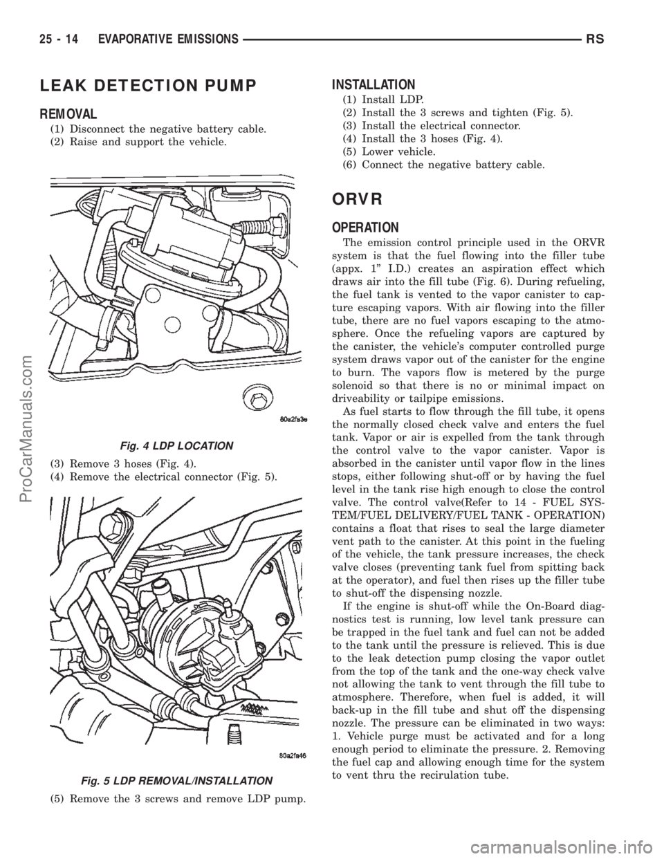
(3) Remove 3 hoses (Fig. 4).
(4) Remove the electrical connector (Fig. 5).
(5) Remove the 3 screws and remove LDP pump.
INSTALLATION
(1) Install LDP.
(2) Install the 3 screws and tighten (Fig. 5).
(3) Install the electrical connector.
(4) Install the 3 hoses (Fig. 4).
(5) Lower vehicle.
(6) Connect the negative battery cable.
ORVR
OPERATION
The emission control principle used in the ORVR
system is that the fuel flowing into the filler tube
(appx. 1º I.D.) creates an aspiration effect which
draws air into the fill tube (Fig. 6). During refueling,
the fuel tank is vented to the vapor canister to cap-
ture escaping vapors. With air flowing into the filler
tube, there are no fuel vapors escaping to the atmo-
sphere. Once the refueling vapors are captured by
the canister, the vehicle's computer controlled purge
system draws vapor out of the canister for the engine
to burn. The vapors flow is metered by the purge
solenoid so that there is no or minimal impact on
driveability or tailpipe emissions.
As fuel starts to flow through the fill tube, it opens
the normally closed check valve and enters the fuel
tank. Vapor or air is expelled from the tank through
the control valve to the vapor canister. Vapor is
absorbed in the canister until vapor flow in the lines
stops, either following shut-off or by having the fuel
level in the tank rise high enough to close the control
valve. The control valve(Refer to 14 - FUEL SYS-
TEM/FUEL DELIVERY/FUEL TANK - OPERATION)
contains a float that rises to seal the large diameter
vent path to the canister. At this point in the fueling
of the vehicle, the tank pressure increases, the check
valve closes (preventing tank fuel from spitting back
at the operator), and fuel then rises up the filler tube
to shut-off the dispensing nozzle.
If the engine is shut-off while the On-Board diag-
nostics test is running, low level tank pressure can
be trapped in the fuel tank and fuel can not be added
to the tank until the pressure is relieved. This is due
to the leak detection pump closing the vapor outlet
from the top of the tank and the one-way check valve
not allowing the tank to vent through the fill tube to
atmosphere. Therefore, when fuel is added, it will
back-up in the fill tube and shut off the dispensing
nozzle. The pressure can be eliminated in two ways:
1. Vehicle purge must be activated and for a long
enough period to eliminate the pressure. 2. Removing
the fuel cap and allowing enough time for the system
to vent thru the recirulation tube.
Fig. 4 LDP LOCATION
Fig. 5 LDP REMOVAL/INSTALLATION
25 - 14 EVAPORATIVE EMISSIONSRS
ProCarManuals.com