blend door actuator CHRYSLER TOWN AND COUNTRY 2002 User Guide
[x] Cancel search | Manufacturer: CHRYSLER, Model Year: 2002, Model line: TOWN AND COUNTRY, Model: CHRYSLER TOWN AND COUNTRY 2002Pages: 2399, PDF Size: 57.96 MB
Page 2254 of 2399

REMOVAL
(1) Disconnect and isolate the battery negative
cable.
(2) Disconnect the headlamp and dash wire har-
ness connector for the A/C pressure transducer from
the transducer connector receptacle (Fig. 3).
(3) Using an open end wrench, unscrew the A/C
pressure transducer from the fitting on the liquid
line between the filter-drier and the expansion valve.
(4) Remove the seal from the A/C pressure trans-
ducer fitting and discard.
INSTALLATION
(1) Lubricate a new rubber O-ring seal with clean
refrigerant oil and install it on the A/C pressure
transducer fitting.
(2) Using an open end wrench, install and tighten
the A/C pressure transducer onto the fitting on the
liquid line between the filter-drier and the expansion
valve.
(3) Reconnect the headlamp and dash wire harness
connector for the A/C pressure transducer to the
transducer connector receptacle.
(4) Reconnect the battery negative cable.
BLEND DOOR ACTUATOR
DESCRIPTION
The blend door actuators are reversible, 12-volt
Direct Current (DC), servo motors. Models with the
single zone heater and air conditioner system have a
single blend air door, which is controlled by a singleblend door actuator. Models with the optional dual
zone front heater and air conditioner system have
dual blend air doors, which are controlled by two
blend door actuators. The single zone blend door
actuator is located on the driver side end of the heat-
er-A/C housing unit, close to the dash panel. In the
dual zone system, the same blend door actuator used
for the single zone system becomes the passenger
blend door actuator, and is mechanically connected to
only the passenger side blend air door. In the dual
zone system, a second separate blend door actuator is
also located on the driver side end of the heater-A/C
housing unit close to the instrument panel, and is
mechanically connected to only the driver side blend
air door.
The blend door actuators are interchangeable with
each other, as well as with the actuators for the
mode door and the recirculation air door. Each actua-
tor is contained within an identical black molded
plastic housing with an integral wire connector
receptacle. Two integral mounting tabs allow the
actuator to be secured with two screws to the heater-
A/C unit housing. Each actuator also has an identical
output shaft with splines that connects it to the link-
age that drives the proper blend air door. The blend
door actuators do not require mechanical indexing to
the blend door linkage, as they are electronically cal-
ibrated by the heater-A/C control module. The blend
door actuators cannot be adjusted or repaired and, if
damaged or faulty, they must be replaced.
OPERATION
Each blend door actuator is connected to the heat-
er-A/C control module through the vehicle electrical
system by a dedicated two-wire take out and connec-
tor of the HVAC wire harness. The blend door actua-
tor can move the blend air door in two directions.
When the heater-A/C control module pulls the volt-
age on one side of the motor connection high and the
other connection low, the blend air door will move in
one direction. When the module reverses the polarity
of the voltage to the motor, the blend air door moves
in the opposite direction. When the module makes
the voltage to both connections high or both connec-
tions low, the blend air door stops and will not move.
These same motor connections also provide a feed-
back signal to the heater-A/C control module. This
feedback signal allows the module to monitor the
operation and relative positions of the blend door
actuator and the blend air door. The heater-A/C con-
trol module learns the blend air door stop positions
during the calibration procedure and will store a
Diagnostic Trouble Code (DTC) for any problems it
detects in the blend door actuator circuits. The blend
door actuator can be diagnosed using a DRBIIItscan
tool. Refer to the appropriate diagnostic information.
Fig. 3 A/C Pressure Transducer
1 - RIGHT FRONT STRUT TOWER
2 - CONNECTOR
3 - A/C PRESSURE TRANSDUCER
4 - RIGHT WIPER MODULE DRAIN TUBE
5 - HIGH SIDE SERVICE PORT
6 - LIQUID LINE
RSCONTROLS - FRONT24-11
A/C PRESSURE TRANSDUCER (Continued)
ProCarManuals.com
Page 2255 of 2399
REMOVAL
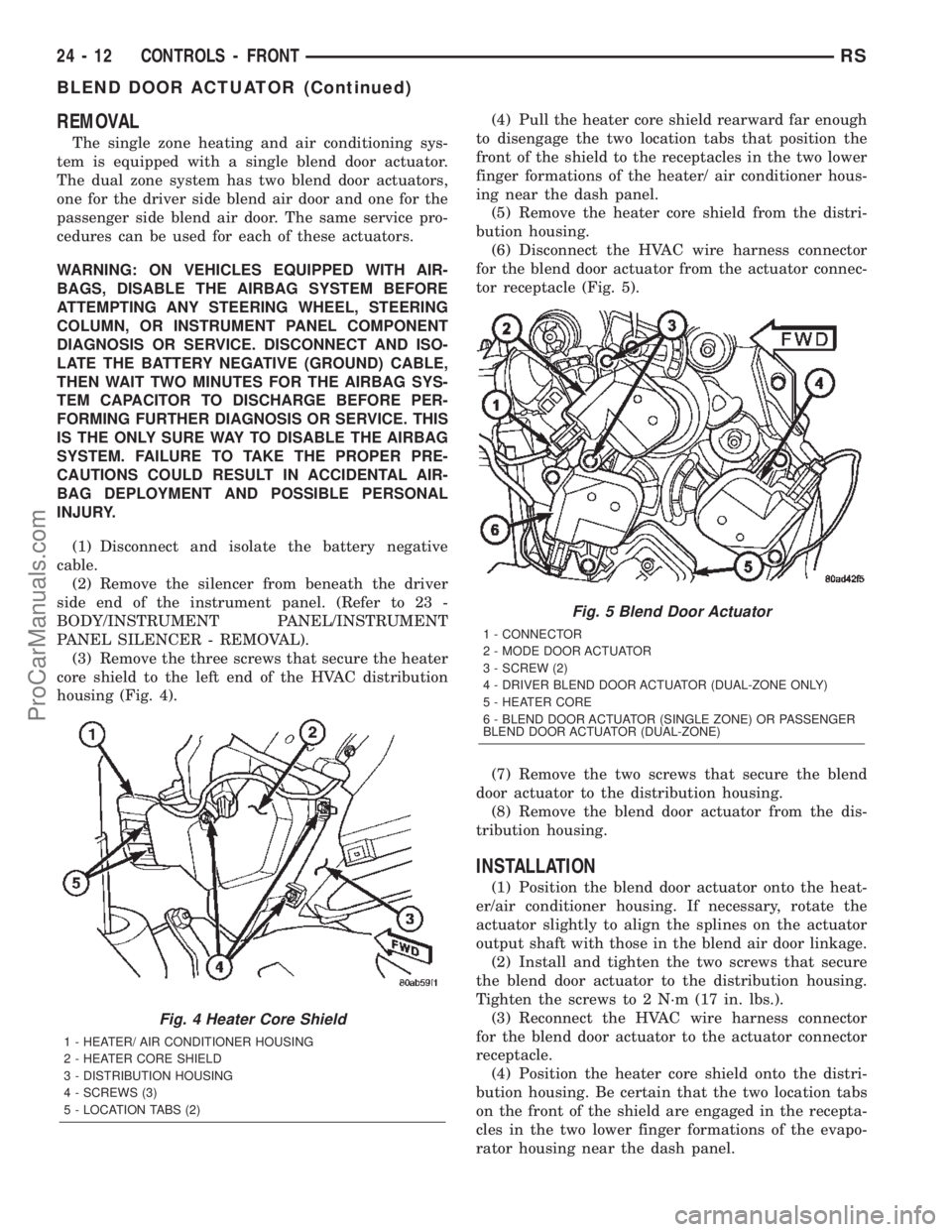
The single zone heating and air conditioning sys-
tem is equipped with a single blend door actuator.
The dual zone system has two blend door actuators,
one for the driver side blend air door and one for the
passenger side blend air door. The same service pro-
cedures can be used for each of these actuators.
WARNING: ON VEHICLES EQUIPPED WITH AIR-
BAGS, DISABLE THE AIRBAG SYSTEM BEFORE
ATTEMPTING ANY STEERING WHEEL, STEERING
COLUMN, OR INSTRUMENT PANEL COMPONENT
DIAGNOSIS OR SERVICE. DISCONNECT AND ISO-
LATE THE BATTERY NEGATIVE (GROUND) CABLE,
THEN WAIT TWO MINUTES FOR THE AIRBAG SYS-
TEM CAPACITOR TO DISCHARGE BEFORE PER-
FORMING FURTHER DIAGNOSIS OR SERVICE. THIS
IS THE ONLY SURE WAY TO DISABLE THE AIRBAG
SYSTEM. FAILURE TO TAKE THE PROPER PRE-
CAUTIONS COULD RESULT IN ACCIDENTAL AIR-
BAG DEPLOYMENT AND POSSIBLE PERSONAL
INJURY.
(1) Disconnect and isolate the battery negative
cable.
(2) Remove the silencer from beneath the driver
side end of the instrument panel. (Refer to 23 -
BODY/INSTRUMENT PANEL/INSTRUMENT
PANEL SILENCER - REMOVAL).
(3) Remove the three screws that secure the heater
core shield to the left end of the HVAC distribution
housing (Fig. 4).(4) Pull the heater core shield rearward far enough
to disengage the two location tabs that position the
front of the shield to the receptacles in the two lower
finger formations of the heater/ air conditioner hous-
ing near the dash panel.
(5) Remove the heater core shield from the distri-
bution housing.
(6) Disconnect the HVAC wire harness connector
for the blend door actuator from the actuator connec-
tor receptacle (Fig. 5).
(7) Remove the two screws that secure the blend
door actuator to the distribution housing.
(8) Remove the blend door actuator from the dis-
tribution housing.
INSTALLATION
(1) Position the blend door actuator onto the heat-
er/air conditioner housing. If necessary, rotate the
actuator slightly to align the splines on the actuator
output shaft with those in the blend air door linkage.
(2) Install and tighten the two screws that secure
the blend door actuator to the distribution housing.
Tighten the screws to 2 N´m (17 in. lbs.).
(3) Reconnect the HVAC wire harness connector
for the blend door actuator to the actuator connector
receptacle.
(4) Position the heater core shield onto the distri-
bution housing. Be certain that the two location tabs
on the front of the shield are engaged in the recepta-
cles in the two lower finger formations of the evapo-
rator housing near the dash panel.
Fig. 4 Heater Core Shield
1 - HEATER/ AIR CONDITIONER HOUSING
2 - HEATER CORE SHIELD
3 - DISTRIBUTION HOUSING
4 - SCREWS (3)
5 - LOCATION TABS (2)
Fig. 5 Blend Door Actuator
1 - CONNECTOR
2 - MODE DOOR ACTUATOR
3 - SCREW (2)
4 - DRIVER BLEND DOOR ACTUATOR (DUAL-ZONE ONLY)
5 - HEATER CORE
6 - BLEND DOOR ACTUATOR (SINGLE ZONE) OR PASSENGER
BLEND DOOR ACTUATOR (DUAL-ZONE)
24 - 12 CONTROLS - FRONTRS
BLEND DOOR ACTUATOR (Continued)
ProCarManuals.com
Page 2256 of 2399
(5) Install and tighten the three screws that secure
the heater core shield to the left end of the heater/air
conditioner housing. Tighten the screws to 2 N´m (17
in. lbs.).
(6) Reinstall the silencer under the driver side end
of the instrument panel. (Refer to 23 - BODY/IN-
STRUMENT PANEL/INSTRUMENT PANEL
SILENCER - INSTALLATION).
(7) Reconnect the battery negative cable.
(8) Perform the heater-A/C control calibration pro-
cedure. (Refer to 24 - HEATING & AIR CONDITION-
ING/CONTROLS - FRONT/A/C-HEATER CONTROL
- STANDARD PROCEDURE - HEATER-A/C CON-
TROL CALIBRATION).
BLOWER MOTOR RELAY
DESCRIPTION
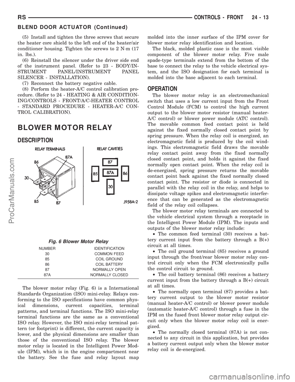
The blower motor relay (Fig. 6) is a International
Standards Organization (ISO) mini-relay. Relays con-
forming to the ISO specifications have common phys-
ical dimensions, current capacities, terminal
patterns, and terminal functions. The ISO mini-relay
terminal functions are the same as a conventional
ISO relay. However, the ISO mini-relay terminal pat-
tern (or footprint) is different, the current capacity is
lower, and the physical dimensions are smaller than
those of the conventional ISO relay. The blower
motor relay is located in the Intelligent Power Mod-
ule (IPM), which is in the engine compartment near
the battery. See the fuse and relay layout mapmolded into the inner surface of the IPM cover for
blower motor relay identification and location.
The black, molded plastic case is the most visible
component of the blower motor relay. Five male
spade-type terminals extend from the bottom of the
base to connect the relay to the vehicle electrical sys-
tem, and the ISO designation for each terminal is
molded into the base adjacent to each terminal.
OPERATION
The blower motor relay is an electromechanical
switch that uses a low current input from the Front
Control Module (FCM) to control the high current
output to the blower motor resistor (manual heater-
A/C control) or blower power module (ATC control).
The movable common feed contact point is held
against the fixed normally closed contact point by
spring pressure. When the relay coil is energized, an
electromagnetic field is produced by the coil wind-
ings. This electromagnetic field draws the movable
relay contact point away from the fixed normally
closed contact point, and holds it against the fixed
normally open contact point. When the relay coil is
de-energized, spring pressure returns the movable
contact point back against the fixed normally closed
contact point. The resistor or diode is connected in
parallel with the relay coil in the relay, and helps to
dissipate voltage spikes and electromagnetic interfer-
ence that can be generated as the electromagnetic
field of the relay coil collapses.
The blower motor relay terminals are connected to
the vehicle electrical system through a receptacle in
the Intelligent Power Module (IPM). The inputs and
outputs of the blower motor relay include:
²The common feed terminal (30) receives a bat-
tery current input from the battery through a B(+)
circuit at all times.
²The coil ground terminal (85) receives a ground
input through the front/rear blower motor relay con-
trol circuit only when the FCM electronically pulls
the control circuit to ground.
²The coil battery terminal (86) receives a battery
current input from the battery through a B(+) circuit
at all times.
²The normally open terminal (87) provides a bat-
tery current output to the blower motor resistor
(manual heater-A/C control) or blower power module
(automatic heater-A/C control) through a fuse in the
IPM on the fused front blower motor relay output cir-
cuit only when the blower motor relay coil is ener-
gized.
²The normally closed terminal (87A) is not con-
nected to any circuit in this application, but provides
a battery current output only when the blower motor
relay coil is de-energized.
Fig. 6 Blower Motor Relay
NUMBER IDENTIFICATION
30 COMMON FEED
85 COIL GROUND
86 COIL BATTERY
87 NORMALLY OPEN
87A NORMALLY CLOSED
RSCONTROLS - FRONT24-13
BLEND DOOR ACTUATOR (Continued)
ProCarManuals.com
Page 2267 of 2399

INFRARED TEMPERATURE
SENSOR
DESCRIPTION
The infrared temperature sensor consists of two
infrared transducers that are concealed behind a
clear lens located near the bottom of the center panel
outlet near the top of the instrument panel center
bezel (Fig. 19). These sensors are used only on mod-
els equipped with the optional Automatic Tempera-
ture Control (ATC) heating and air conditioning
system. A molded plastic connector receptacle on the
bottom of the panel outlet unit is concealed behind
the center bezel. A short, dedicated jumper wire har-
ness routed behind the center bezel connects the sen-
sors directly to the ATC heater-A/C control module
near the bottom of the center bezel. The infrared
temperature sensor is integral to the center bezel
panel outlet unit. The infrared sensors cannot be
adjusted or repaired and, if faulty or damaged, the
center bezel panel outlet unit must be replaced.
OPERATION
The dual infrared temperature sensors provide
independent measurement inputs to the Automatic
Temperature Control (ATC) heater-A/C control mod-
ule that indicates the surface temperature of the
driver seat and front seat passenger seat occupants.
By using a surface temperature measurement, rather
than an air temperature measurement, the ATC sys-
tem is able to adjust itself to the comfort level as per-
ceived by the occupant. This allows the system to
detect and compensate for other ambient conditions
affecting comfort levels, such as solar heat gain orevaporative heat loss. The ATC system logic responds
to the infrared sensor inputs by calculating and
adjusting the air flow temperature and air flow rate
needed to properly obtain and maintain the individ-
ually selected comfort level temperatures of both the
driver and passenger seat occupants. The ATC heat-
er-A/C control module continually monitors the infra-
red sensor circuits, and will store a Diagnostic
Trouble Code (DTC) for any problem it detects. This
DTC information can be retrieved and the infrared
temperature sensor diagnosed using a DRBIIItscan
tool. Refer to the appropriate diagnostic information.
MODE DOOR ACTUATOR
DESCRIPTION
The mode door actuator is a reversible, 12-volt
Direct Current (DC), servo motor (Fig. 20). The sin-
gle mode door actuator is located on the driver side
end of the heater-A/C housing unit, close to the top of
the distribution housing. The mode door actuator is
mechanically connected to the mode door. The mode
door actuator is interchangeable with the actuators
for the blend air door(s) and the recirculation air
door. Each actuator is contained within an identical
black molded plastic housing with an integral wire
connector receptacle. Two integral mounting tabs
allow the actuator to be secured with two screws to
the heater-A/C unit housing. Each actuator also has
an identical output shaft with splines that connects
Fig. 19 Infrared Temperature Sensor
1 - INSTRUMENT PANEL CENTER BEZEL
2 - CENTER BEZEL OUTLETS
3 - INFRARED TEMPERATURE SENSOR
Fig. 20 Mode Door Actuator
1 - CONNECTOR
2 - MODE DOOR ACTUATOR
3 - SCREW (2)
4 - DRIVER BLEND DOOR ACTUATOR (DUAL-ZONE ONLY)
5 - HEATER CORE
6 - BLEND DOOR ACTUATOR (SINGLE ZONE) OR PASSENGER
BLEND DOOR ACTUATOR (DUAL-ZONE)
24 - 24 CONTROLS - FRONTRS
ProCarManuals.com
Page 2268 of 2399
it to the linkage that drives the mode door. The mode
door actuator does not require mechanical indexing
to the mode door linkage, as it is electronically cali-
brated by the heater-A/C control module. The mode
door actuator cannot be adjusted or repaired and, if
damaged or faulty, it must be replaced.
OPERATION
The mode door actuator is connected to the heater-
A/C control module through the vehicle electrical sys-
tem by a dedicated two-wire take out and connector
of the HVAC wire harness. The mode door actuator
can move the mode door in two directions. When the
heater-A/C control module pulls the voltage on one
side of the motor connection high and the other con-
nection low, the mode door will move in one direction.
When the module reverses the polarity of the voltage
to the motor, the mode door moves in the opposite
direction. When the module makes the voltage to
both connections high or both connections low, the
mode door stops and will not move. These same
motor connections also provide a feedback signal to
the heater-A/C control module. This feedback signal
allows the module to monitor the operation and rela-
tive position of the mode door actuator and the mode
door. The heater-A/C control module learns the mode
door stop positions during the calibration procedure
and will store a Diagnostic Trouble Code (DTC) for
any problems it detects in the mode door actuator
circuits. The mode door actuator can be diagnosed
using a DRBIIItscan tool. Refer to the appropriate
diagnostic information.
REMOVAL
WARNING: ON VEHICLES EQUIPPED WITH AIR-
BAGS, DISABLE THE AIRBAG SYSTEM BEFORE
ATTEMPTING ANY STEERING WHEEL, STEERING
COLUMN, OR INSTRUMENT PANEL COMPONENT
DIAGNOSIS OR SERVICE. DISCONNECT AND ISO-
LATE THE BATTERY NEGATIVE (GROUND) CABLE,
THEN WAIT TWO MINUTES FOR THE AIRBAG SYS-
TEM CAPACITOR TO DISCHARGE BEFORE PER-
FORMING FURTHER DIAGNOSIS OR SERVICE. THIS
IS THE ONLY SURE WAY TO DISABLE THE AIRBAG
SYSTEM. FAILURE TO TAKE THE PROPER PRE-
CAUTIONS COULD RESULT IN ACCIDENTAL AIR-
BAG DEPLOYMENT AND POSSIBLE PERSONAL
INJURY.
(1) Disconnect and isolate the battery negative
cable.
(2) Remove the silencer from beneath the driver
side end of the instrument panel. (Refer to 23 -
BODY/INSTRUMENT PANEL/INSTRUMENT
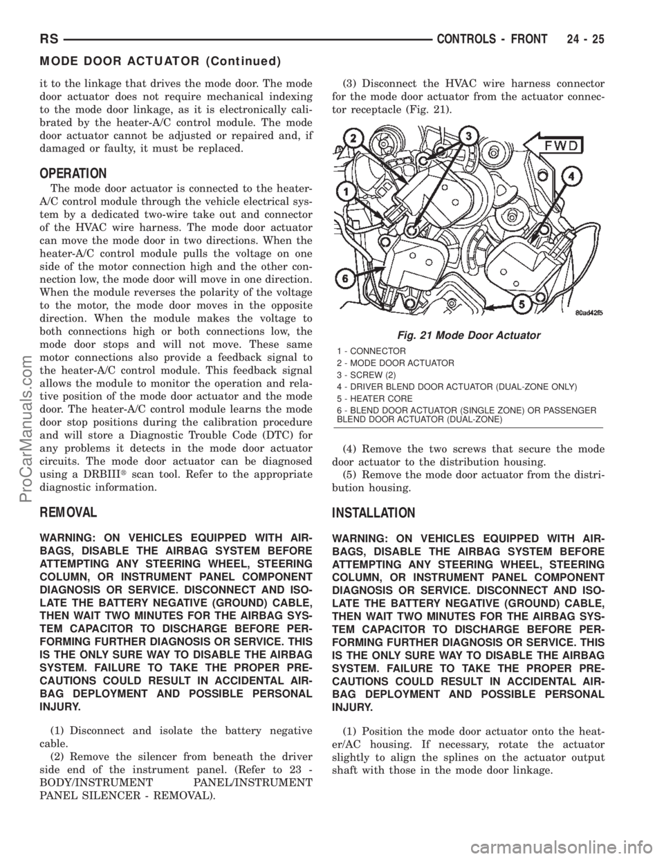
PANEL SILENCER - REMOVAL).(3) Disconnect the HVAC wire harness connector
for the mode door actuator from the actuator connec-
tor receptacle (Fig. 21).
(4) Remove the two screws that secure the mode
door actuator to the distribution housing.
(5) Remove the mode door actuator from the distri-
bution housing.
INSTALLATION
WARNING: ON VEHICLES EQUIPPED WITH AIR-
BAGS, DISABLE THE AIRBAG SYSTEM BEFORE
ATTEMPTING ANY STEERING WHEEL, STEERING
COLUMN, OR INSTRUMENT PANEL COMPONENT
DIAGNOSIS OR SERVICE. DISCONNECT AND ISO-
LATE THE BATTERY NEGATIVE (GROUND) CABLE,
THEN WAIT TWO MINUTES FOR THE AIRBAG SYS-
TEM CAPACITOR TO DISCHARGE BEFORE PER-
FORMING FURTHER DIAGNOSIS OR SERVICE. THIS
IS THE ONLY SURE WAY TO DISABLE THE AIRBAG
SYSTEM. FAILURE TO TAKE THE PROPER PRE-
CAUTIONS COULD RESULT IN ACCIDENTAL AIR-
BAG DEPLOYMENT AND POSSIBLE PERSONAL
INJURY.
(1) Position the mode door actuator onto the heat-
er/AC housing. If necessary, rotate the actuator
slightly to align the splines on the actuator output
shaft with those in the mode door linkage.
Fig. 21 Mode Door Actuator
1 - CONNECTOR
2 - MODE DOOR ACTUATOR
3 - SCREW (2)
4 - DRIVER BLEND DOOR ACTUATOR (DUAL-ZONE ONLY)
5 - HEATER CORE
6 - BLEND DOOR ACTUATOR (SINGLE ZONE) OR PASSENGER
BLEND DOOR ACTUATOR (DUAL-ZONE)
RSCONTROLS - FRONT24-25
MODE DOOR ACTUATOR (Continued)
ProCarManuals.com
Page 2270 of 2399
connector for the power module from the module con-
nector receptacle.
(5) Reach through the glove box opening to access
and disconnect the blower motor pigtail wire connec-
tor from the power module connector receptacle.
(6) Remove the two screws that secure the power
module to the evaporator housing.
(7) Remove the power module from the evaporator
housing.
INSTALLATION
WARNING: ON VEHICLES EQUIPPED WITH AIR-
BAGS, DISABLE THE AIRBAG SYSTEM BEFORE
ATTEMPTING ANY STEERING WHEEL, STEERING
COLUMN, OR INSTRUMENT PANEL COMPONENT
DIAGNOSIS OR SERVICE. DISCONNECT AND ISO-
LATE THE BATTERY NEGATIVE (GROUND) CABLE,
THEN WAIT TWO MINUTES FOR THE AIRBAG SYS-
TEM CAPACITOR TO DISCHARGE BEFORE PER-
FORMING FURTHER DIAGNOSIS OR SERVICE. THIS
IS THE ONLY SURE WAY TO DISABLE THE AIRBAG
SYSTEM. FAILURE TO TAKE THE PROPER PRE-
CAUTIONS COULD RESULT IN ACCIDENTAL AIR-
BAG DEPLOYMENT AND POSSIBLE PERSONAL
INJURY.
(1) Position the power module into the evaporator
housing.
(2) Install and tighten the two screws that secure
the power module to the evaporator housing. Tighten
the screws to 2 N´m (18 in. lbs.).
(3) Reconnect the blower motor pigtail wire con-
nector to the power module connector receptacle.
(4) Reconnect the instrument panel wire harness
connector for the power module to the module con-
nector receptacle.
(5) Flex both sides of the glove box bin inward
near the top far enough for the rubber glove box stop
bumpers to clear the sides of the glove box opening,
then roll the glove box upward.
(6) Close and latch the glove box.
(7) Reconnect the battery negative cable.
RECIRCULATION DOOR
ACTUATOR
DESCRIPTION
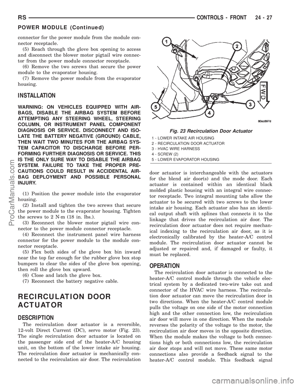
The recirculation door actuator is a reversible,
12-volt Direct Current (DC), servo motor (Fig. 23).
The single recirculation door actuator is located on
the passenger side end of the heater-A/C housing
unit, on the bottom of the lower intake air housing.
The recirculation door actuator is mechanically con-
nected to the recirculation air door. The recirculationdoor actuator is interchangeable with the actuators
for the blend air door(s) and the mode door. Each
actuator is contained within an identical black
molded plastic housing with an integral wire connec-
tor receptacle. Two integral mounting tabs allow the
actuator to be secured with two screws to the lower
intake air housing. Each actuator also has an identi-
cal output shaft with splines that connects it to the
linkage that drives the recirculation air door. The
recirculation door actuator does not require mechan-
ical indexing to the recirculation air door, as it is
electronically calibrated by the heater-A/C control
module. The recirculation door actuator cannot be
adjusted or repaired and, if damaged or faulty, it
must be replaced.
OPERATION
The recirculation door actuator is connected to the
heater-A/C control module through the vehicle elec-
trical system by a dedicated two-wire take out and
connector of the HVAC wire harness. The recircula-
tion door actuator can move the recirculation door in
two directions. When the heater-A/C control module
pulls the voltage on one side of the motor connection
high and the other connection low, the recirculation
air door will move in one direction. When the module
reverses the polarity of the voltage to the motor, the
recirculation air door moves in the opposite direction.
When the module makes the voltage to both connec-
tions high or both connections low, the recirculation
air door stops and will not move. These same motor
connections also provide a feedback signal to the
heater-A/C control module. This feedback signal
Fig. 23 Recirculation Door Actuator
1 - LOWER INTAKE AIR HOUSING
2 - RECIRCULATION DOOR ACTUATOR
3 - HVAC WIRE HARNESS
4 - SCREW (2)
5 - LOWER EVAPORATOR HOUSING
RSCONTROLS - FRONT24-27
POWER MODULE (Continued)
ProCarManuals.com
Page 2272 of 2399

CONTROLS - REAR
TABLE OF CONTENTS
page page
A/C-HEATER CONTROL
REMOVAL.............................29
INSTALLATION.........................29
BLEND DOOR ACTUATOR
DESCRIPTION.........................30
OPERATION...........................30
REMOVAL.............................31
INSTALLATION.........................31
BLOWER MOTOR RELAY
DESCRIPTION.........................32
OPERATION...........................32
DIAGNOSIS AND TESTING - BLOWER
MOTOR RELAY.......................33
REMOVAL.............................33
INSTALLATION.........................34
BLOWER MOTOR RESISTOR
DESCRIPTION.........................34OPERATION...........................34
DIAGNOSIS AND TESTING - BLOWER
MOTOR RESISTOR....................35
REMOVAL.............................35
INSTALLATION.........................35
INFRARED TEMPERATURE SENSOR
DESCRIPTION.........................36
OPERATION...........................36
MODE DOOR ACTUATOR
REMOVAL.............................36
INSTALLATION.........................37
POWER MODULE
DESCRIPTION.........................37
OPERATION...........................37
REMOVAL.............................38
INSTALLATION.........................38
A/C-HEATER CONTROL
REMOVAL
(1) Disconnect and isolate the battery negative
cable.
(2) Using a trim stick or another suitable wide flat
bladed tool, gently pry the top edge of the rear heat-
er-A/C control bezel away from the headliner far
enough to release the two snap clip retainers (Fig. 1).
(3) Pull the rear heater-A/C control and bezel unit
rearward far enough to access the headliner wire
harness connector on the back of the control.
(4) Disconnect the headliner wire harness connec-
tor for the rear heater-A/C control from the control
connector receptacle.
(5) Remove the rear heater-A/C control from the
headliner.
(6) Remove the three screws that secure the rear
heater-A/C control to the bezel (Fig. 2).
(7) Remove the rear heater-A/C control from the
bezel.
INSTALLATION
(1) Position the rear heater-A/C control onto the
bezel.
(2) Install and tighten the three screws that secure
the rear heater-A/C control to the bezel. Tighten the
screws to 2 N´m (17 in. lbs.).
(3) Position the rear heater-A/C control and bezel
unit to the headliner.(4) Reconnect the headliner wire harness connec-
tor for the rear heater-A/C control to the control con-
nector receptacle.
(5) Insert the locator tabs on the back of the rear
heater-A/C control and bezel unit over the forward
edge of the headliner opening for the control.
(6) Slide the rear heater-A/C control and bezel unit
forward far enough to align the snap clips on the
Fig. 1 Heater-A/C Control
1 - TRIM STICK
2 - BEZEL
3 - HEATER-A/C CONTROL
4 - HEADLINER
RSCONTROLS - REAR24-29
ProCarManuals.com
Page 2273 of 2399
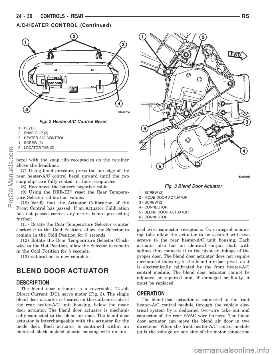
bezel with the snap clip receptacles on the retainer
above the headliner.
(7) Using hand pressure, press the top edge of the
rear heater-A/C control bezel upward until the two
snap clips are fully seated in their receptacles.
(8) Reconnect the battery negative cable.
(9) Using the DRB-IIItreset the Rear Tempera-
ture Selector calibration values.
(10) Verify that the Actuator Calibration of the
Front Control has passed. If an Actuator Calibration
has not passed correct any errors before proceeding
further.
(11) Rotate the Rear Temperature Selector counter
clockwise to the Cold Position, allow the Selector to
remain in the Cold Position for 5 seconds.
(12) Rotate the Rear Temperature Selector Clock-
wise to the Hot Position, allow the Selector to remain
in the Cold Position for 5 seconds.
(13) calibration is now complete.
BLEND DOOR ACTUATOR
DESCRIPTION
The blend door actuator is a reversible, 12-volt
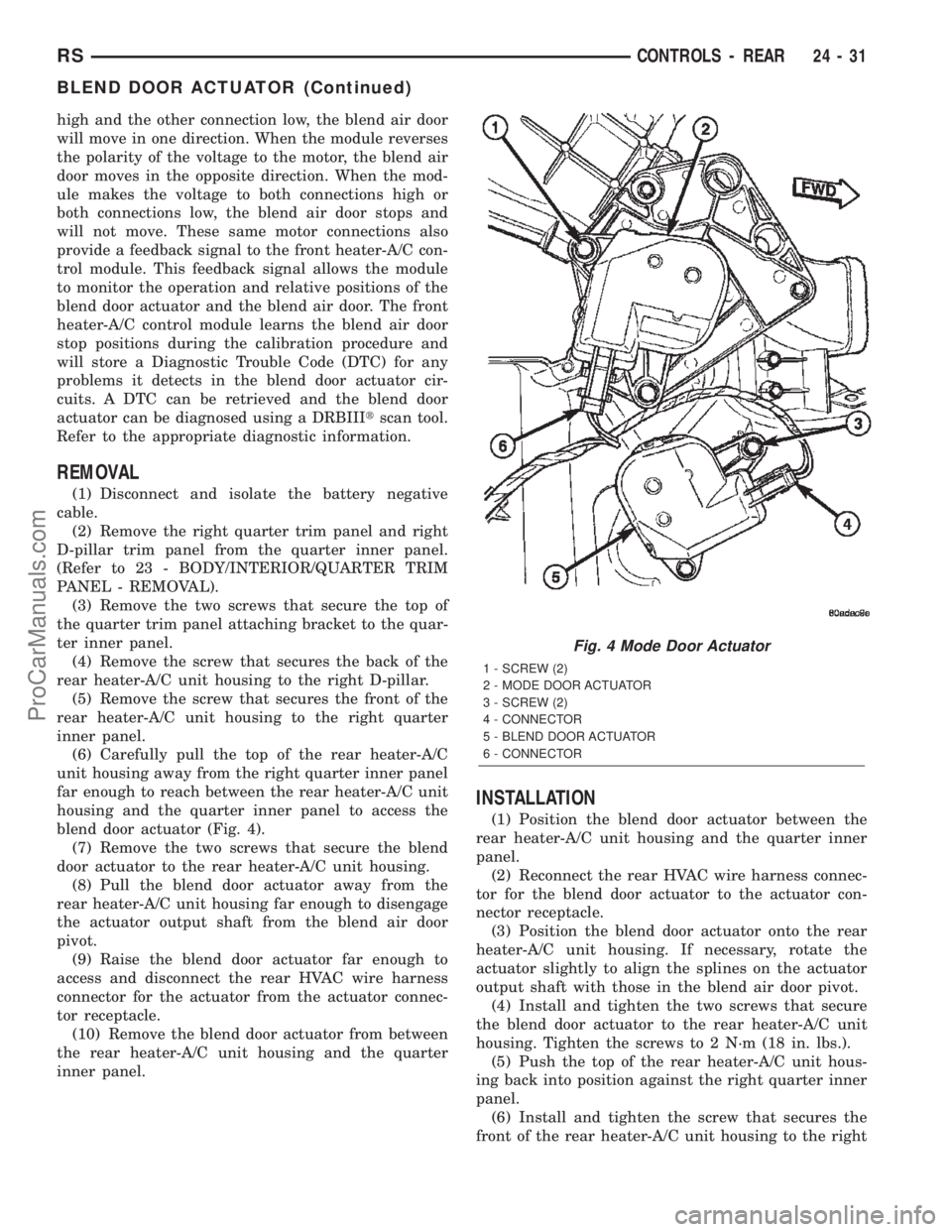
Direct Current (DC), servo motor (Fig. 3). The single
blend door actuator is located on the outboard side of
the rear heater-A/C unit housing, below the mode
door actuator. The blend door actuator is mechani-
cally connected to the blend air door. The blend door
actuator is interchangeable with the actuator for the
mode door. Each actuator is contained within an
identical black molded plastic housing with an inte-gral wire connector receptacle. Two integral mount-
ing tabs allow the actuator to be secured with two
screws to the rear heater-A/C unit housing. Each
actuator also has an identical output shaft with
splines that connects it to the pivot or linkage of the
proper door. The blend door actuator does not require
mechanical indexing to the blend air door pivot, as it
is electronically calibrated by the front heater-A/C
control module. The blend door actuator cannot be
adjusted or repaired and, if damaged or faulty, it
must be replaced.
OPERATION
The blend door actuator is connected to the front
heater-A/C control module through the vehicle elec-
trical system by a dedicated two-wire take out and
connector of the rear HVAC wire harness. The blend
door actuator can move the blend air door in two
directions. When the front heater-A/C control module
pulls the voltage on one side of the motor connection
Fig. 2 Heater-A/C Control Bezel
1 - BEZEL
2 - SNAP CLIP (2)
3 - HEATER-A/C CONTROL
4 - SCREW (3)
5 - LOCATOR TAB (2)
Fig. 3 Blend Door Actuator
1 - SCREW (2)
2 - MODE DOOR ACTUATOR
3 - SCREW (2)
4 - CONNECTOR
5 - BLEND DOOR ACTUATOR
6 - CONNECTOR
24 - 30 CONTROLS - REARRS
A/C-HEATER CONTROL (Continued)
ProCarManuals.com
Page 2274 of 2399
high and the other connection low, the blend air door
will move in one direction. When the module reverses
the polarity of the voltage to the motor, the blend air
door moves in the opposite direction. When the mod-
ule makes the voltage to both connections high or
both connections low, the blend air door stops and
will not move. These same motor connections also
provide a feedback signal to the front heater-A/C con-
trol module. This feedback signal allows the module
to monitor the operation and relative positions of the
blend door actuator and the blend air door. The front
heater-A/C control module learns the blend air door
stop positions during the calibration procedure and
will store a Diagnostic Trouble Code (DTC) for any
problems it detects in the blend door actuator cir-
cuits. A DTC can be retrieved and the blend door
actuator can be diagnosed using a DRBIIItscan tool.
Refer to the appropriate diagnostic information.
REMOVAL
(1) Disconnect and isolate the battery negative
cable.
(2) Remove the right quarter trim panel and right
D-pillar trim panel from the quarter inner panel.
(Refer to 23 - BODY/INTERIOR/QUARTER TRIM
PANEL - REMOVAL).
(3) Remove the two screws that secure the top of
the quarter trim panel attaching bracket to the quar-
ter inner panel.
(4) Remove the screw that secures the back of the
rear heater-A/C unit housing to the right D-pillar.
(5) Remove the screw that secures the front of the
rear heater-A/C unit housing to the right quarter
inner panel.
(6) Carefully pull the top of the rear heater-A/C
unit housing away from the right quarter inner panel
far enough to reach between the rear heater-A/C unit
housing and the quarter inner panel to access the
blend door actuator (Fig. 4).
(7) Remove the two screws that secure the blend
door actuator to the rear heater-A/C unit housing.
(8) Pull the blend door actuator away from the
rear heater-A/C unit housing far enough to disengage
the actuator output shaft from the blend air door
pivot.
(9) Raise the blend door actuator far enough to
access and disconnect the rear HVAC wire harness
connector for the actuator from the actuator connec-
tor receptacle.
(10) Remove the blend door actuator from between
the rear heater-A/C unit housing and the quarter
inner panel.
INSTALLATION
(1) Position the blend door actuator between the
rear heater-A/C unit housing and the quarter inner
panel.
(2) Reconnect the rear HVAC wire harness connec-
tor for the blend door actuator to the actuator con-
nector receptacle.
(3) Position the blend door actuator onto the rear
heater-A/C unit housing. If necessary, rotate the
actuator slightly to align the splines on the actuator
output shaft with those in the blend air door pivot.
(4) Install and tighten the two screws that secure
the blend door actuator to the rear heater-A/C unit
housing. Tighten the screws to 2 N´m (18 in. lbs.).
(5) Push the top of the rear heater-A/C unit hous-
ing back into position against the right quarter inner
panel.
(6) Install and tighten the screw that secures the
front of the rear heater-A/C unit housing to the right
Fig. 4 Mode Door Actuator
1 - SCREW (2)
2 - MODE DOOR ACTUATOR
3 - SCREW (2)
4 - CONNECTOR
5 - BLEND DOOR ACTUATOR
6 - CONNECTOR
RSCONTROLS - REAR24-31
BLEND DOOR ACTUATOR (Continued)
ProCarManuals.com
Page 2275 of 2399
quarter inner panel. Tighten the screw to 11 N´m (97
in. lbs.).
(7) Install and tighten the screw that secures the
back of the rear heater-A/C unit housing to the right
D-pillar. Tighten the screw to 11 N´m (97 in. lbs.).
(8) Install and tighten the two screws that secure
the top of the quarter trim panel attaching bracket to
the quarter inner panel. Tighten the screws to 1.7
N´m (15 in. lbs.).
(9) Reinstall the right quarter trim panel and
right D-pillar trim panel onto the quarter inner
panel. (Refer to 23 - BODY/INTERIOR/QUARTER
TRIM PANEL - INSTALLATION).
(10) Reconnect the battery negative cable.
(11) Perform the heater-A/C control calibration
procedure. (Refer to 24 - HEATING & AIR CONDI-
TIONING/CONTROLS - FRONT/A/C-HEATER CON-
TROL - STANDARD PROCEDURE - HEATER-A/C
CONTROL CALIBRATION).
BLOWER MOTOR RELAY
DESCRIPTION
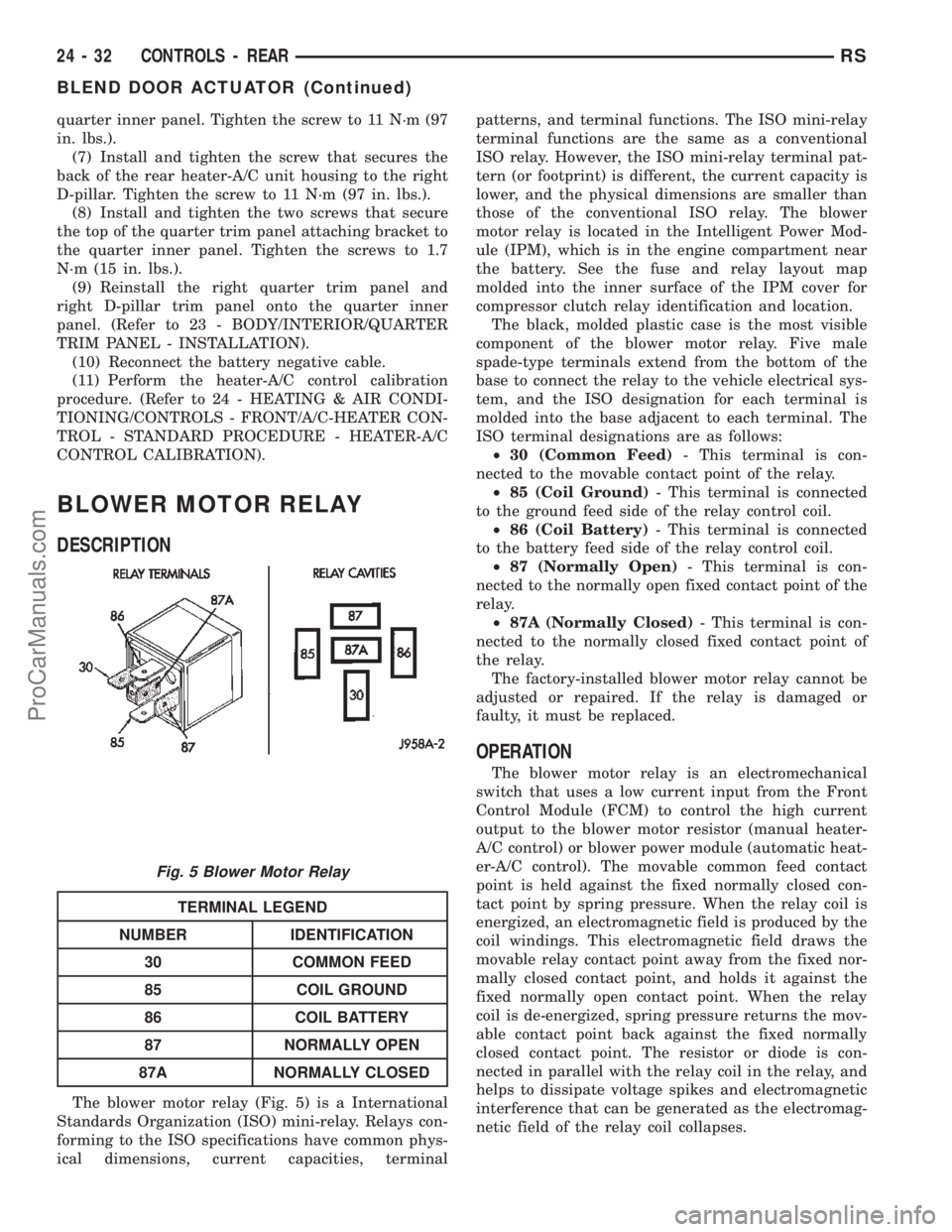
TERMINAL LEGEND
NUMBER IDENTIFICATION
30 COMMON FEED
85 COIL GROUND
86 COIL BATTERY
87 NORMALLY OPEN
87A NORMALLY CLOSED
The blower motor relay (Fig. 5) is a International
Standards Organization (ISO) mini-relay. Relays con-
forming to the ISO specifications have common phys-
ical dimensions, current capacities, terminalpatterns, and terminal functions. The ISO mini-relay
terminal functions are the same as a conventional
ISO relay. However, the ISO mini-relay terminal pat-
tern (or footprint) is different, the current capacity is
lower, and the physical dimensions are smaller than
those of the conventional ISO relay. The blower
motor relay is located in the Intelligent Power Mod-
ule (IPM), which is in the engine compartment near
the battery. See the fuse and relay layout map
molded into the inner surface of the IPM cover for
compressor clutch relay identification and location.
The black, molded plastic case is the most visible
component of the blower motor relay. Five male
spade-type terminals extend from the bottom of the
base to connect the relay to the vehicle electrical sys-
tem, and the ISO designation for each terminal is
molded into the base adjacent to each terminal. The
ISO terminal designations are as follows:
²30 (Common Feed)- This terminal is con-
nected to the movable contact point of the relay.
²85 (Coil Ground)- This terminal is connected
to the ground feed side of the relay control coil.
²86 (Coil Battery)- This terminal is connected
to the battery feed side of the relay control coil.
²87 (Normally Open)- This terminal is con-
nected to the normally open fixed contact point of the
relay.
²87A (Normally Closed)- This terminal is con-
nected to the normally closed fixed contact point of
the relay.
The factory-installed blower motor relay cannot be
adjusted or repaired. If the relay is damaged or
faulty, it must be replaced.
OPERATION
The blower motor relay is an electromechanical
switch that uses a low current input from the Front
Control Module (FCM) to control the high current
output to the blower motor resistor (manual heater-
A/C control) or blower power module (automatic heat-
er-A/C control). The movable common feed contact
point is held against the fixed normally closed con-
tact point by spring pressure. When the relay coil is
energized, an electromagnetic field is produced by the
coil windings. This electromagnetic field draws the
movable relay contact point away from the fixed nor-
mally closed contact point, and holds it against the
fixed normally open contact point. When the relay
coil is de-energized, spring pressure returns the mov-
able contact point back against the fixed normally
closed contact point. The resistor or diode is con-
nected in parallel with the relay coil in the relay, and
helps to dissipate voltage spikes and electromagnetic
interference that can be generated as the electromag-
netic field of the relay coil collapses.
Fig. 5 Blower Motor Relay
24 - 32 CONTROLS - REARRS
BLEND DOOR ACTUATOR (Continued)
ProCarManuals.com