instrument panel CHRYSLER TOWN AND COUNTRY 2002 User Guide
[x] Cancel search | Manufacturer: CHRYSLER, Model Year: 2002, Model line: TOWN AND COUNTRY, Model: CHRYSLER TOWN AND COUNTRY 2002Pages: 2399, PDF Size: 57.96 MB
Page 181 of 2399
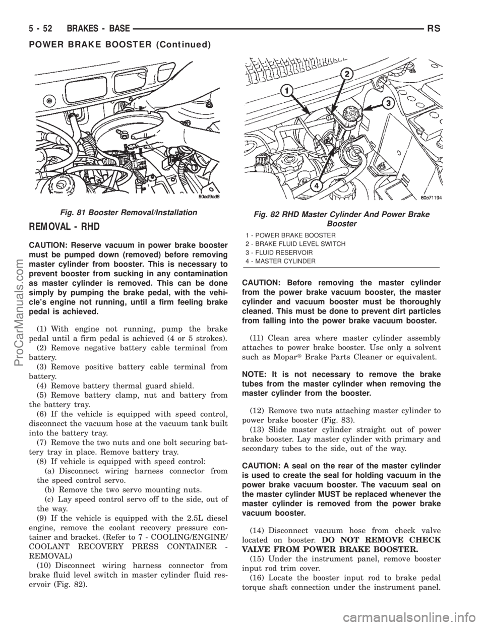
REMOVAL - RHD
CAUTION: Reserve vacuum in power brake booster
must be pumped down (removed) before removing
master cylinder from booster. This is necessary to
prevent booster from sucking in any contamination
as master cylinder is removed. This can be done
simply by pumping the brake pedal, with the vehi-
cle's engine not running, until a firm feeling brake
pedal is achieved.
(1) With engine not running, pump the brake
pedal until a firm pedal is achieved (4 or 5 strokes).
(2) Remove negative battery cable terminal from
battery.
(3) Remove positive battery cable terminal from
battery.
(4) Remove battery thermal guard shield.
(5) Remove battery clamp, nut and battery from
the battery tray.
(6) If the vehicle is equipped with speed control,
disconnect the vacuum hose at the vacuum tank built
into the battery tray.
(7) Remove the two nuts and one bolt securing bat-
tery tray in place. Remove battery tray.
(8) If vehicle is equipped with speed control:
(a) Disconnect wiring harness connector from
the speed control servo.
(b) Remove the two servo mounting nuts.
(c) Lay speed control servo off to the side, out of
the way.
(9) If the vehicle is equipped with the 2.5L diesel
engine, remove the coolant recovery pressure con-
tainer and bracket. (Refer to 7 - COOLING/ENGINE/
COOLANT RECOVERY PRESS CONTAINER -
REMOVAL)
(10) Disconnect wiring harness connector from
brake fluid level switch in master cylinder fluid res-
ervoir (Fig. 82).CAUTION: Before removing the master cylinder
from the power brake vacuum booster, the master
cylinder and vacuum booster must be thoroughly
cleaned. This must be done to prevent dirt particles
from falling into the power brake vacuum booster.
(11) Clean area where master cylinder assembly
attaches to power brake booster. Use only a solvent
such as MopartBrake Parts Cleaner or equivalent.
NOTE: It is not necessary to remove the brake
tubes from the master cylinder when removing the
master cylinder from the booster.
(12) Remove two nuts attaching master cylinder to
power brake booster (Fig. 83).
(13) Slide master cylinder straight out of power
brake booster. Lay master cylinder with primary and
secondary tubes to the side, out of the way.
CAUTION: A seal on the rear of the master cylinder
is used to create the seal for holding vacuum in the
power brake vacuum booster. The vacuum seal on
the master cylinder MUST be replaced whenever the
master cylinder is removed from the power brake
vacuum booster.
(14) Disconnect vacuum hose from check valve
located on booster.DO NOT REMOVE CHECK
VALVE FROM POWER BRAKE BOOSTER.
(15) Under the instrument panel, remove booster
input rod trim cover.
(16) Locate the booster input rod to brake pedal
torque shaft connection under the instrument panel.
Fig. 81 Booster Removal/InstallationFig. 82 RHD Master Cylinder And Power Brake
Booster
1 - POWER BRAKE BOOSTER
2 - BRAKE FLUID LEVEL SWITCH
3 - FLUID RESERVOIR
4 - MASTER CYLINDER
5 - 52 BRAKES - BASERS
POWER BRAKE BOOSTER (Continued)
ProCarManuals.com
Page 184 of 2399
(12) Connect wiring harness connector to brake
fluid level switch in the master cylinder fluid reser-
voir (Fig. 77).
(13) Connect primary and secondary brake tubes
to ABS ICU or non-ABS junction block (Fig. 78).
Tighten the tube nuts to 17 N´m (145 in lbs.).
(14) Install wiper module (unit). (Refer to 8 -
ELECTRICAL/WIPERS/WASHERS/WIPER MOD-
ULE - INSTALLATION)
(15) If equipped with speed control, install speed
control servo and connect wiring connector. Tighten
the mounting nuts to a torque of 14 N´m (124 in.
lbs.).
(16) Install the battery tray. Install the two nuts
and one bolt attaching the battery tray to the vehicle.
Tighten the bolt and nuts to a torque of 14 N´m (124
in. lbs.).
(17) If vehicle is equipped with speed control, con-
nect the servo vacuum hose to the vacuum tank on
the battery tray.
(18) Install the air inlet resonator and hoses as an
assembly on the throttle body and air cleaner hous-
ing. Securely tighten hose clamp at air cleaner hous-
ing and throttle body.
(19) Secure the engine coolant filler neck to the
battery tray with its mounting screw.
(20) Install the battery, clamp and mounting nut.
(21) Install the positive battery cable on the bat-
tery.
(22) Install the negative battery cable on the bat-
tery.
(23) Install the battery thermal guard shield.
(24) Bleed the base brakes as necessary. (Refer to
5 - BRAKES - STANDARD PROCEDURE)
(25) Road test vehicle to ensure operation of the
brakes.
INSTALLATION - RHD
(1) Position power brake booster on dash panel
using the reverse procedure of its removal (Fig. 86).
(2) Below instrument panel, first install the two
upper nuts mounting the booster to the dash panel,
drawing it into place, then install the two lower
mounting nuts. Tighten the mounting nuts to a
torque of 29 N´m (250 in. lbs.).
(3) Using lubriplate, or equivalent, coat the sur-
face of the brake pedal torque shaft pin where it con-
tacts the booster input rod.
CAUTION: When installing the brake pedal torque
shaft pin on the power brake booster input rod, do
not re-use the old retaining clip.
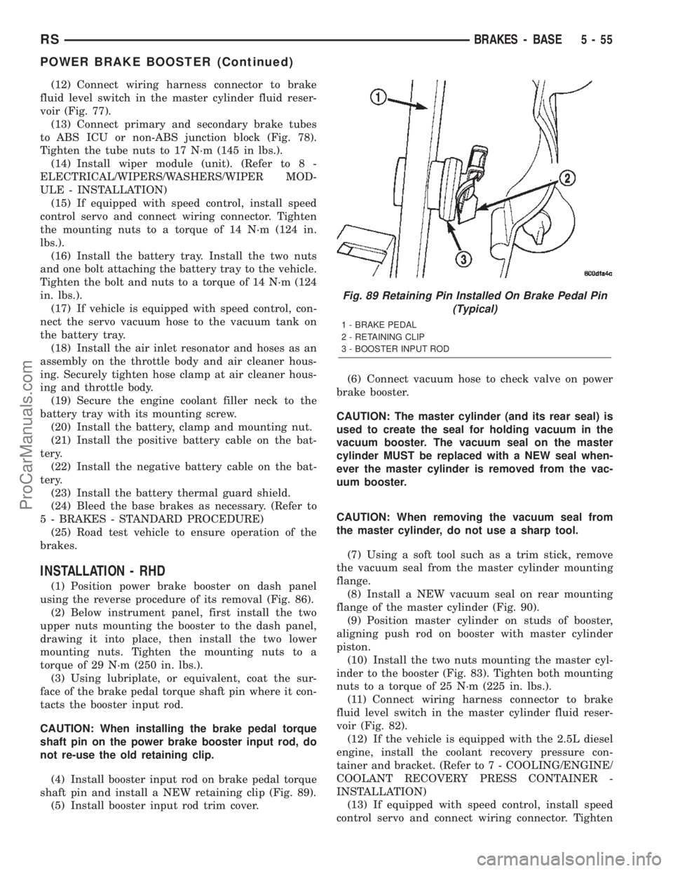
(4) Install booster input rod on brake pedal torque
shaft pin and install a NEW retaining clip (Fig. 89).
(5) Install booster input rod trim cover.(6) Connect vacuum hose to check valve on power
brake booster.
CAUTION: The master cylinder (and its rear seal) is
used to create the seal for holding vacuum in the
vacuum booster. The vacuum seal on the master
cylinder MUST be replaced with a NEW seal when-
ever the master cylinder is removed from the vac-
uum booster.
CAUTION: When removing the vacuum seal from
the master cylinder, do not use a sharp tool.
(7) Using a soft tool such as a trim stick, remove
the vacuum seal from the master cylinder mounting
flange.
(8) Install a NEW vacuum seal on rear mounting
flange of the master cylinder (Fig. 90).
(9) Position master cylinder on studs of booster,
aligning push rod on booster with master cylinder
piston.
(10) Install the two nuts mounting the master cyl-
inder to the booster (Fig. 83). Tighten both mounting
nuts to a torque of 25 N´m (225 in. lbs.).
(11) Connect wiring harness connector to brake
fluid level switch in the master cylinder fluid reser-
voir (Fig. 82).
(12) If the vehicle is equipped with the 2.5L diesel
engine, install the coolant recovery pressure con-
tainer and bracket. (Refer to 7 - COOLING/ENGINE/
COOLANT RECOVERY PRESS CONTAINER -
INSTALLATION)
(13) If equipped with speed control, install speed
control servo and connect wiring connector. Tighten
Fig. 89 Retaining Pin Installed On Brake Pedal Pin
(Typical)
1 - BRAKE PEDAL
2 - RETAINING CLIP
3 - BOOSTER INPUT ROD
RSBRAKES - BASE5-55
POWER BRAKE BOOSTER (Continued)
ProCarManuals.com
Page 202 of 2399
(3) Remove sill scuff plate from left door sill.
(4) Remove the left side kick panel.
(5) Remove the silencer panel under the instru-
ment panel.
(6) Remove the steering column cover from the
lower instrument panel.
(7) Remove the reinforcement from the lower
instrument panel.
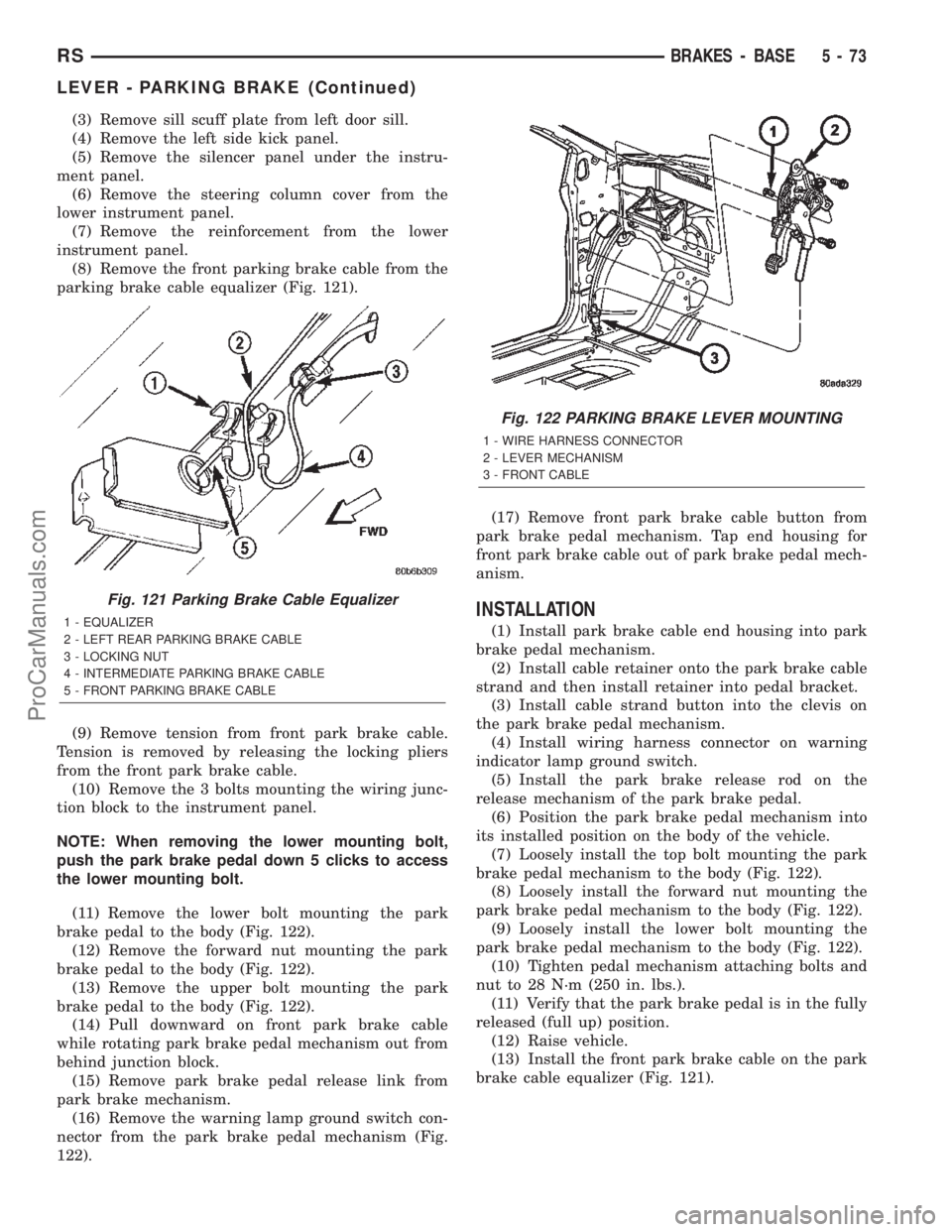
(8) Remove the front parking brake cable from the
parking brake cable equalizer (Fig. 121).
(9) Remove tension from front park brake cable.
Tension is removed by releasing the locking pliers
from the front park brake cable.
(10) Remove the 3 bolts mounting the wiring junc-
tion block to the instrument panel.
NOTE: When removing the lower mounting bolt,
push the park brake pedal down 5 clicks to access
the lower mounting bolt.
(11) Remove the lower bolt mounting the park
brake pedal to the body (Fig. 122).
(12) Remove the forward nut mounting the park
brake pedal to the body (Fig. 122).
(13) Remove the upper bolt mounting the park
brake pedal to the body (Fig. 122).
(14) Pull downward on front park brake cable
while rotating park brake pedal mechanism out from
behind junction block.
(15) Remove park brake pedal release link from
park brake mechanism.
(16) Remove the warning lamp ground switch con-
nector from the park brake pedal mechanism (Fig.
122).(17) Remove front park brake cable button from
park brake pedal mechanism. Tap end housing for
front park brake cable out of park brake pedal mech-
anism.
INSTALLATION
(1) Install park brake cable end housing into park
brake pedal mechanism.
(2) Install cable retainer onto the park brake cable
strand and then install retainer into pedal bracket.
(3) Install cable strand button into the clevis on
the park brake pedal mechanism.
(4) Install wiring harness connector on warning
indicator lamp ground switch.
(5) Install the park brake release rod on the
release mechanism of the park brake pedal.
(6) Position the park brake pedal mechanism into
its installed position on the body of the vehicle.
(7) Loosely install the top bolt mounting the park
brake pedal mechanism to the body (Fig. 122).
(8) Loosely install the forward nut mounting the
park brake pedal mechanism to the body (Fig. 122).
(9) Loosely install the lower bolt mounting the
park brake pedal mechanism to the body (Fig. 122).
(10) Tighten pedal mechanism attaching bolts and
nut to 28 N´m (250 in. lbs.).
(11) Verify that the park brake pedal is in the fully
released (full up) position.
(12) Raise vehicle.
(13) Install the front park brake cable on the park
brake cable equalizer (Fig. 121).
Fig. 121 Parking Brake Cable Equalizer
1 - EQUALIZER
2 - LEFT REAR PARKING BRAKE CABLE
3 - LOCKING NUT
4 - INTERMEDIATE PARKING BRAKE CABLE
5 - FRONT PARKING BRAKE CABLE
Fig. 122 PARKING BRAKE LEVER MOUNTING
1 - WIRE HARNESS CONNECTOR
2 - LEVER MECHANISM
3 - FRONT CABLE
RSBRAKES - BASE5-73
LEVER - PARKING BRAKE (Continued)
ProCarManuals.com
Page 203 of 2399
NOTE: If the original lever assembly is being used,
the lever mechanism auto adjuster spring tension
will need to be reset. (Refer to 5 - BRAKES/PARK-
ING BRAKE - STANDARD PROCEDURE)
(14) Lower vehicle.
(15) Remove the lock-out pin (if a new lever has
been installed) from the automatic cable adjuster on
the park brake pedal mechanism.
(16) Install the electrical junction block on the
instrument panel.
(17) Install the reinforcement on the lower instru-
ment panel.
(18) Install the steering column lower cover on the
lower instrument panel.
(19) Install the silencer panel under the instru-
ment panel.
(20) Install the left side kick panel.
(21) Install the sill scuff plate on the lower sill of
the left door.
(22) Install the negative (ground) cable on the bat-
tery.
(23) Cycle the park brake pedal one time. This will
seat the park brake cables and will allow the auto-
matic self adjuster to properly tension the park brake
cables.
LEVER - PARKING BRAKE
(EXPORT)
REMOVAL - PARKING BRAKE LEVER AND
FRONT CABLE
(1)Raise vehicle. (Refer to LUBRICATION & MAIN-
TENANCE/HOISTING - STANDARD PROCEDURE)
(2) Grasp the exposed section of the front parking
brake cable and pull rearward on it. While holding
the park brake in this position, install a pair of lock-
ing pliers on the front parking brake cable just rear-
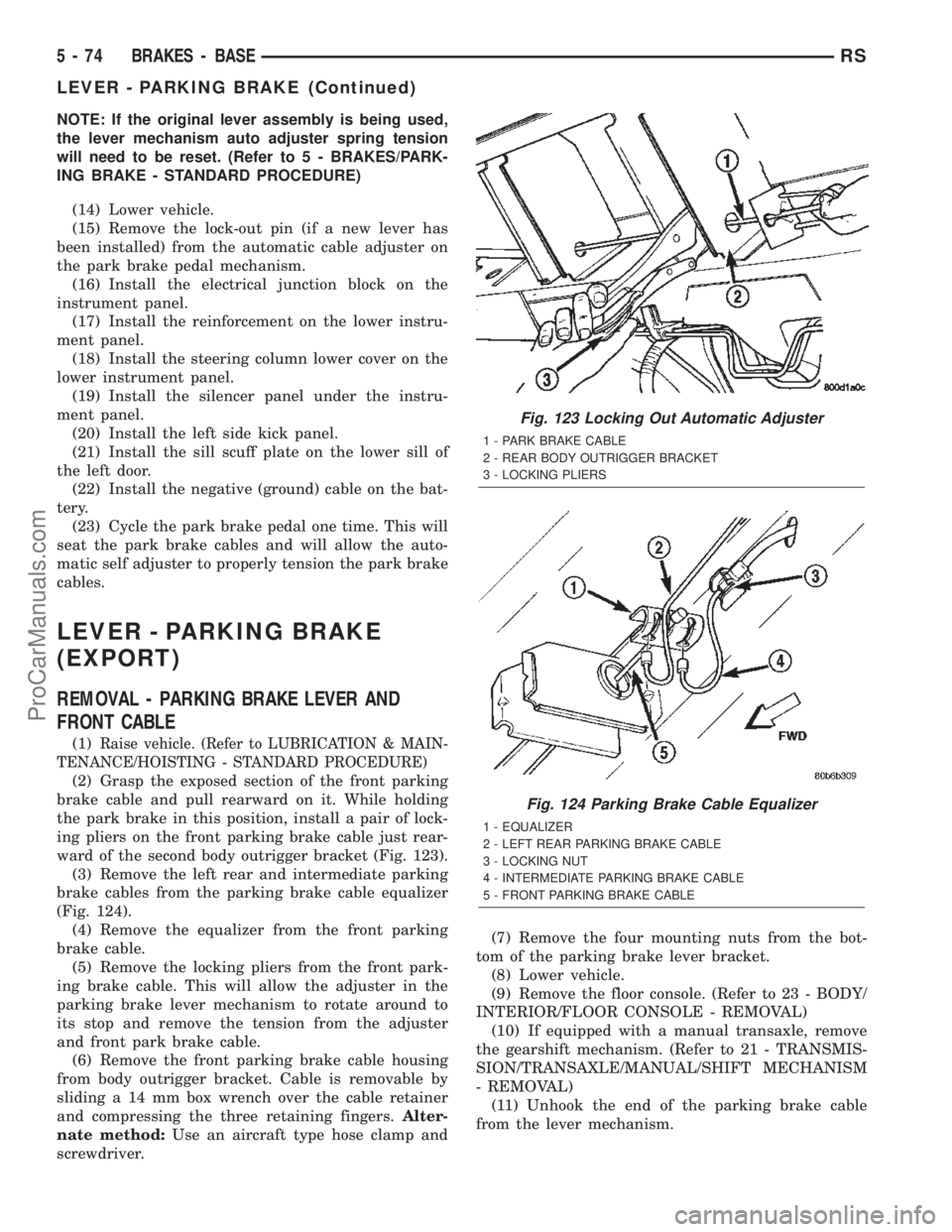
ward of the second body outrigger bracket (Fig. 123).
(3) Remove the left rear and intermediate parking
brake cables from the parking brake cable equalizer
(Fig. 124).
(4) Remove the equalizer from the front parking
brake cable.
(5) Remove the locking pliers from the front park-
ing brake cable. This will allow the adjuster in the
parking brake lever mechanism to rotate around to
its stop and remove the tension from the adjuster
and front park brake cable.
(6) Remove the front parking brake cable housing
from body outrigger bracket. Cable is removable by
sliding a 14 mm box wrench over the cable retainer
and compressing the three retaining fingers.Alter-
nate method:Use an aircraft type hose clamp and
screwdriver.(7) Remove the four mounting nuts from the bot-
tom of the parking brake lever bracket.
(8) Lower vehicle.
(9) Remove the floor console. (Refer to 23 - BODY/
INTERIOR/FLOOR CONSOLE - REMOVAL)
(10) If equipped with a manual transaxle, remove
the gearshift mechanism. (Refer to 21 - TRANSMIS-
SION/TRANSAXLE/MANUAL/SHIFT MECHANISM
- REMOVAL)
(11) Unhook the end of the parking brake cable
from the lever mechanism.
Fig. 123 Locking Out Automatic Adjuster
1 - PARK BRAKE CABLE
2 - REAR BODY OUTRIGGER BRACKET
3 - LOCKING PLIERS
Fig. 124 Parking Brake Cable Equalizer
1 - EQUALIZER
2 - LEFT REAR PARKING BRAKE CABLE
3 - LOCKING NUT
4 - INTERMEDIATE PARKING BRAKE CABLE
5 - FRONT PARKING BRAKE CABLE
5 - 74 BRAKES - BASERS
LEVER - PARKING BRAKE (Continued)
ProCarManuals.com
Page 233 of 2399
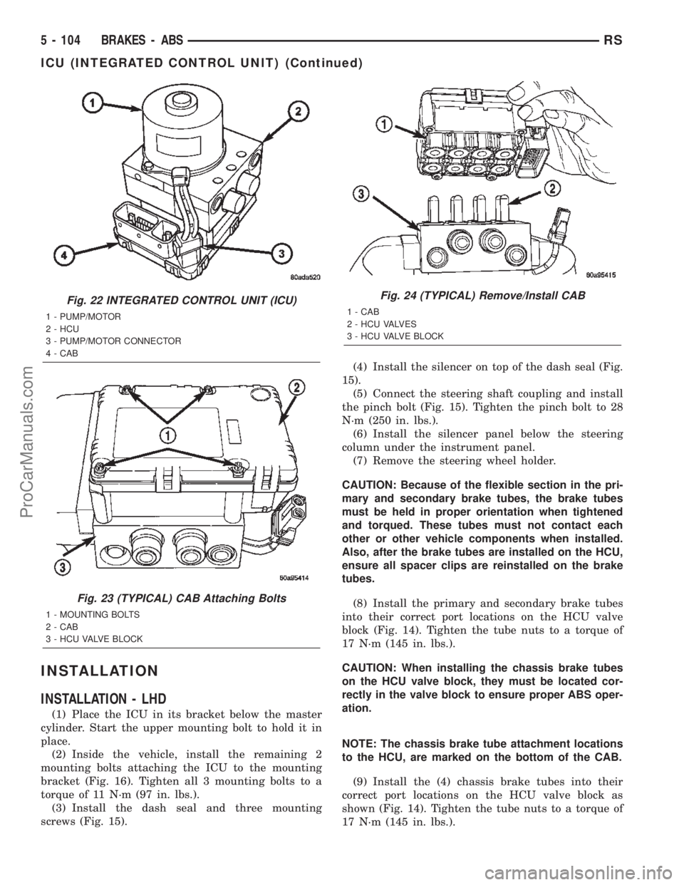
INSTALLATION
INSTALLATION - LHD
(1) Place the ICU in its bracket below the master
cylinder. Start the upper mounting bolt to hold it in
place.
(2) Inside the vehicle, install the remaining 2
mounting bolts attaching the ICU to the mounting
bracket (Fig. 16). Tighten all 3 mounting bolts to a
torque of 11 N´m (97 in. lbs.).
(3) Install the dash seal and three mounting
screws (Fig. 15).(4) Install the silencer on top of the dash seal (Fig.
15).
(5) Connect the steering shaft coupling and install
the pinch bolt (Fig. 15). Tighten the pinch bolt to 28
N´m (250 in. lbs.).
(6) Install the silencer panel below the steering
column under the instrument panel.
(7) Remove the steering wheel holder.
CAUTION: Because of the flexible section in the pri-
mary and secondary brake tubes, the brake tubes
must be held in proper orientation when tightened
and torqued. These tubes must not contact each
other or other vehicle components when installed.
Also, after the brake tubes are installed on the HCU,
ensure all spacer clips are reinstalled on the brake
tubes.
(8) Install the primary and secondary brake tubes
into their correct port locations on the HCU valve
block (Fig. 14). Tighten the tube nuts to a torque of
17 N´m (145 in. lbs.).
CAUTION: When installing the chassis brake tubes
on the HCU valve block, they must be located cor-
rectly in the valve block to ensure proper ABS oper-
ation.
NOTE: The chassis brake tube attachment locations
to the HCU, are marked on the bottom of the CAB.
(9) Install the (4) chassis brake tubes into their
correct port locations on the HCU valve block as
shown (Fig. 14). Tighten the tube nuts to a torque of
17 N´m (145 in. lbs.).
Fig. 22 INTEGRATED CONTROL UNIT (ICU)
1 - PUMP/MOTOR
2 - HCU
3 - PUMP/MOTOR CONNECTOR
4 - CAB
Fig. 23 (TYPICAL) CAB Attaching Bolts
1 - MOUNTING BOLTS
2 - CAB
3 - HCU VALVE BLOCK
Fig. 24 (TYPICAL) Remove/Install CAB
1 - CAB
2 - HCU VALVES
3 - HCU VALVE BLOCK
5 - 104 BRAKES - ABSRS
ICU (INTEGRATED CONTROL UNIT) (Continued)
ProCarManuals.com
Page 244 of 2399
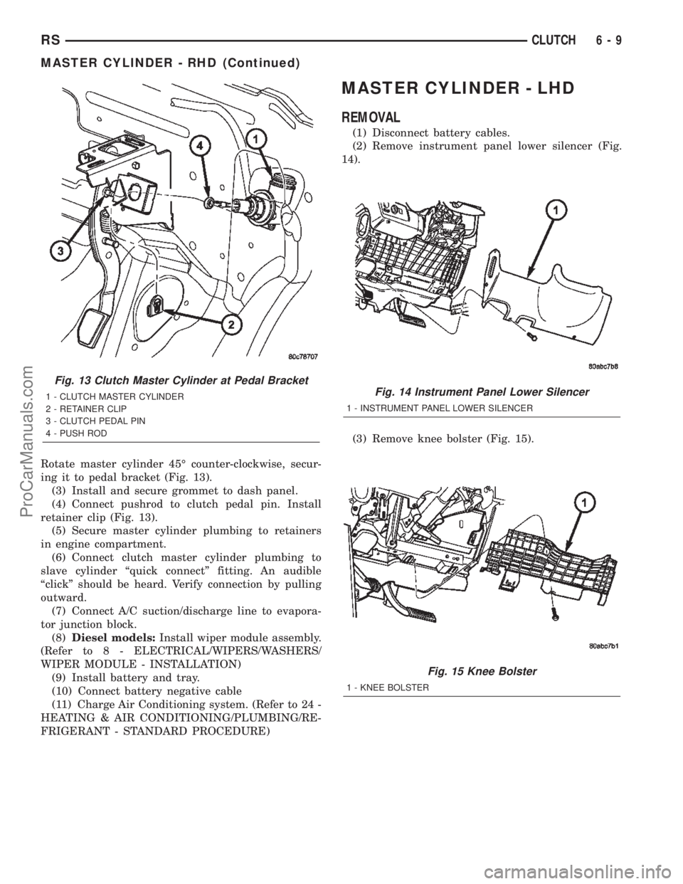
Rotate master cylinder 45É counter-clockwise, secur-
ing it to pedal bracket (Fig. 13).
(3) Install and secure grommet to dash panel.
(4) Connect pushrod to clutch pedal pin. Install
retainer clip (Fig. 13).
(5) Secure master cylinder plumbing to retainers
in engine compartment.
(6) Connect clutch master cylinder plumbing to
slave cylinder ªquick connectº fitting. An audible
ªclickº should be heard. Verify connection by pulling
outward.
(7) Connect A/C suction/discharge line to evapora-
tor junction block.
(8)Diesel models:Install wiper module assembly.
(Refer to 8 - ELECTRICAL/WIPERS/WASHERS/
WIPER MODULE - INSTALLATION)
(9) Install battery and tray.
(10) Connect battery negative cable
(11) Charge Air Conditioning system. (Refer to 24 -
HEATING & AIR CONDITIONING/PLUMBING/RE-
FRIGERANT - STANDARD PROCEDURE)
MASTER CYLINDER - LHD
REMOVAL
(1) Disconnect battery cables.
(2) Remove instrument panel lower silencer (Fig.
14).
(3) Remove knee bolster (Fig. 15).
Fig. 13 Clutch Master Cylinder at Pedal Bracket
1 - CLUTCH MASTER CYLINDER
2 - RETAINER CLIP
3 - CLUTCH PEDAL PIN
4 - PUSH RODFig. 14 Instrument Panel Lower Silencer
1 - INSTRUMENT PANEL LOWER SILENCER
Fig. 15 Knee Bolster
1 - KNEE BOLSTER
RSCLUTCH6-9
MASTER CYLINDER - RHD (Continued)
ProCarManuals.com
Page 246 of 2399
(5) Install windshield wiper module assembly
(Refer to 8 - ELECTRICAL/WIPERS/WASHERS/
WIPER MODULE - INSTALLATION).
(6) Install battery tray.
(7) Install battery.
(8) Install battery shield.
(9) Connect master cylinder pushrod to clutch
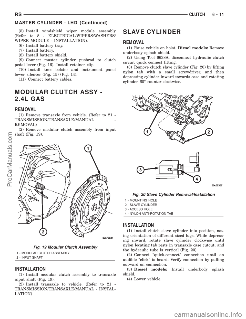
pedal lever (Fig. 16). Install retainer clip.
(10) Install knee bolster and instrument panel
lower silencer (Fig. 15) (Fig. 14).
(11) Connect battery cables.
MODULAR CLUTCH ASSY -
2.4L GAS
REMOVAL
(1) Remove transaxle from vehicle. (Refer to 21 -
TRANSMISSION/TRANSAXLE/MANUAL -
REMOVAL)
(2) Remove modular clutch assembly from input
shaft (Fig. 19).
INSTALLATION
(1) Install modular clutch assembly to transaxle
input shaft (Fig. 19).
(2) Install transaxle to vehicle. (Refer to 21 -
TRANSMISSION/TRANSAXLE/MANUAL - INSTAL-
LATION)
SLAVE CYLINDER
REMOVAL
(1) Raise vehicle on hoist.Diesel models:Remove
underbody splash shield.
(2) Using Tool 6638A, disconnect hydraulic clutch
circuit quick connect fitting.
(3) Remove clutch slave cylinder (Fig. 20) by lifting
nylon tab with a small screwdriver, and then
depressing cylinder inward towards case and rotating
cylinder 60É counter-clockwise.
INSTALLATION
(1) Install clutch slave cylinder into position, not-
ing orientation of different sized lugs. While depress-
ing inward, rotate slave cylinder clockwise until
nylon locating tab rests in transaxle case cutout, and
the hydraulic tube is vertical (Fig. 20).
(2) Connect ªquick-connectº connection until an
audible ªclickº is heard. Verify connection by pulling
outward on connection.
(3)Diesel models:Install underbody splash
shield.
(4) Lower vehicle.
Fig. 19 Modular Clutch Assembly
1 - MODULAR CLUTCH ASSEMBLY
2 - INPUT SHAFT
Fig. 20 Slave Cylinder Removal/Installation
1 - MOUNTING HOLE
2 - SLAVE CYLINDER
3 - ACCESS HOLE
4 - NYLON ANTI-ROTATION TAB
RSCLUTCH6-11
MASTER CYLINDER - LHD (Continued)
ProCarManuals.com
Page 320 of 2399
AUDIO
TABLE OF CONTENTS
page page
AUDIO
DESCRIPTION..........................1
OPERATION............................1
DIAGNOSIS AND TESTING - AUDIO..........1
ANTENNA BODY AND CABLE
DESCRIPTION..........................4
OPERATION............................4
DIAGNOSIS AND TESTING - ANTENNA BODY
AND CABLE..........................4
REMOVAL.............................4
INSTALLATION..........................5
ANTENNA MODULE - EXPORT
DESCRIPTION..........................6
OPERATION............................6
DIAGNOSIS AND TESTING - ANTENNA
MODULE - EXPORT....................6
REMOVAL.............................7
INSTALLATION..........................7
CD CHANGER
DESCRIPTION..........................7
OPERATION............................7
REMOVAL.............................7
INSTALLATION..........................7
INSTRUMENT PANEL ANTENNA CABLE
REMOVAL.............................8INSTALLATION..........................8
QUARTER GLASS INTEGRAL ANTENNA -
EXPORT
DESCRIPTION..........................8
OPERATION............................8
DIAGNOSIS AND TESTING - QUARTER
GLASS INTEGRAL ANTENNA - EXPORT.....8
RADIO
DIAGNOSIS AND TESTING - RADIO..........9
REMOVAL.............................9
INSTALLATION.........................10
RADIO NOISE SUPPRESSION COMPONENTS
DESCRIPTION.........................10
OPERATION...........................10
REMOTE SWITCHES
DESCRIPTION.........................11
OPERATION...........................11
DIAGNOSIS AND TESTING - REMOTE
SWITCHES..........................11
REMOVAL.............................12
INSTALLATION.........................12
SPEAKER
DIAGNOSIS AND TESTING - SPEAKER......12
REMOVAL.............................13
INSTALLATION.........................14
AUDIO
DESCRIPTION
There are four different system combinations avail-
able on this model. The available radio options are:
²AM/FM Cassette
²AM/FM Compact Disc with Compact Disc
changer controls
²AM/FM Cassette with single Compact Disc
Player and Compact Disc changer controls
²AM/FM Cassette with Compact Disc changer
controls
²AM/FM Cassette with Compact Disc player, rear
seat audio system and Compact Disc changer con-
trols.
The rear seat audio system allows passengers to
listen to a different music source, through head-
phones, other than what is playing through the vehi-
cles speaker system. A remote control is provided for
functions such as changing stations, tracks, disc and
modes while listening to rear seat audio. The radiomust be turned ON to use the rear seat audio sys-
tem.
All factory installed radio receivers are stereo Elec-
tronically Tuned Radios (ETR) and include and elec-
tronic digital clock function.
OPERATION
Operating instructions for the factory installed
audio systems can be found in the Owner's Manual
provided with this vehicle.
DIAGNOSIS AND TESTING - AUDIO
Any diagnosis of the Audio system should
begin with the use of the DRB IIItdiagnostic
tool. For information on the use of the DRB
IIIt, refer to the appropriate Diagnostic Service
Manual.
Refer to the appropriate wiring information. The
wiring information includes wiring diagrams, proper
wire and connector repair procedures, details of wire
harness routing and retention, connector pin-out
RSAUDIO8A-1
ProCarManuals.com
Page 321 of 2399
information and location views for the various wire
harness connectors, splices and grounds.
WARNING: ON VEHICLES EQUIPPED WITH AIR-
BAGS, REFER TO ELECTRICAL, RESTRAINTS
BEFORE ATTEMPTING ANY STEERING WHEEL,STEERING COLUMN, OR INSTRUMENT PANEL
COMPONENT DIAGNOSIS OR SERVICE. FAILURE
TO TAKE THE PROPER PRECAUTIONS COULD
RESULT IN ACCIDENTAL AIRBAG DEPLOYMENT
AND POSSIBLE PERSONAL INJURY.
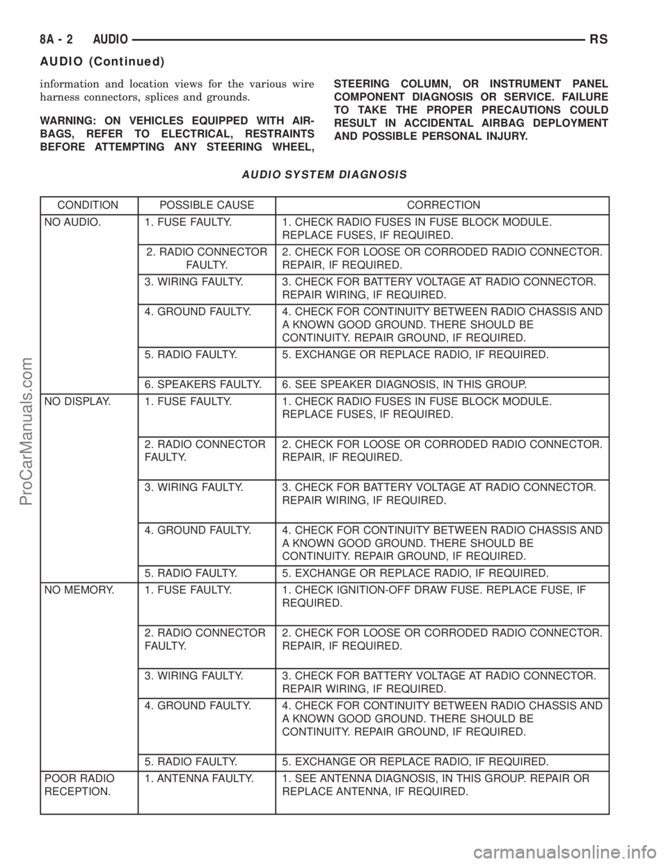
AUDIO SYSTEM DIAGNOSIS
CONDITION POSSIBLE CAUSE CORRECTION
NO AUDIO. 1. FUSE FAULTY. 1. CHECK RADIO FUSES IN FUSE BLOCK MODULE.
REPLACE FUSES, IF REQUIRED.
2. RADIO CONNECTOR
FAULTY.2. CHECK FOR LOOSE OR CORRODED RADIO CONNECTOR.
REPAIR, IF REQUIRED.
3. WIRING FAULTY. 3. CHECK FOR BATTERY VOLTAGE AT RADIO CONNECTOR.
REPAIR WIRING, IF REQUIRED.
4. GROUND FAULTY. 4. CHECK FOR CONTINUITY BETWEEN RADIO CHASSIS AND
A KNOWN GOOD GROUND. THERE SHOULD BE
CONTINUITY. REPAIR GROUND, IF REQUIRED.
5. RADIO FAULTY. 5. EXCHANGE OR REPLACE RADIO, IF REQUIRED.
6. SPEAKERS FAULTY. 6. SEE SPEAKER DIAGNOSIS, IN THIS GROUP.
NO DISPLAY. 1. FUSE FAULTY. 1. CHECK RADIO FUSES IN FUSE BLOCK MODULE.
REPLACE FUSES, IF REQUIRED.
2. RADIO CONNECTOR
FAULTY.2. CHECK FOR LOOSE OR CORRODED RADIO CONNECTOR.
REPAIR, IF REQUIRED.
3. WIRING FAULTY. 3. CHECK FOR BATTERY VOLTAGE AT RADIO CONNECTOR.
REPAIR WIRING, IF REQUIRED.
4. GROUND FAULTY. 4. CHECK FOR CONTINUITY BETWEEN RADIO CHASSIS AND
A KNOWN GOOD GROUND. THERE SHOULD BE
CONTINUITY. REPAIR GROUND, IF REQUIRED.
5. RADIO FAULTY. 5. EXCHANGE OR REPLACE RADIO, IF REQUIRED.
NO MEMORY. 1. FUSE FAULTY. 1. CHECK IGNITION-OFF DRAW FUSE. REPLACE FUSE, IF
REQUIRED.
2. RADIO CONNECTOR
FAULTY.2. CHECK FOR LOOSE OR CORRODED RADIO CONNECTOR.
REPAIR, IF REQUIRED.
3. WIRING FAULTY. 3. CHECK FOR BATTERY VOLTAGE AT RADIO CONNECTOR.
REPAIR WIRING, IF REQUIRED.
4. GROUND FAULTY. 4. CHECK FOR CONTINUITY BETWEEN RADIO CHASSIS AND
A KNOWN GOOD GROUND. THERE SHOULD BE
CONTINUITY. REPAIR GROUND, IF REQUIRED.
5. RADIO FAULTY. 5. EXCHANGE OR REPLACE RADIO, IF REQUIRED.
POOR RADIO
RECEPTION.1. ANTENNA FAULTY. 1. SEE ANTENNA DIAGNOSIS, IN THIS GROUP. REPAIR OR
REPLACE ANTENNA, IF REQUIRED.
8A - 2 AUDIORS
AUDIO (Continued)
ProCarManuals.com
Page 323 of 2399
ANTENNA BODY AND CABLE
DESCRIPTION
All models use a fixed-length stainless steel rod-
type antenna mast, installed at the right front fender
of the vehicle. The antenna mast is connected to the
center wire of the coaxial antenna cable, and is not
grounded to any part of the vehicle.
OPERATION
To minimize static, the antenna base must have a
good ground. The coaxial antenna cable shield (the
outer wire mesh of the cable) is grounded to the
antenna base and the radio chassis.
The antenna coaxial cable has an additional dis-
connect, located near the right end of the instrument
panel. This additional disconnect allows the instru-
ment panel assembly to be removed and installed
without removing the radio.
The factory-installed Electronically Tuned Radios
(ETRs) automatically compensate for radio antenna
trim. Therefore, no antenna trimmer adjustment is
required or possible when replacing the receiver or
the antenna.
DIAGNOSIS AND TESTING - ANTENNA BODY
AND CABLE
WARNING: ON VEHICLES EQUIPPED WITH AIR-
BAGS, REFER TO ELECTRICAL, RESTRAINTS
BEFORE ATTEMPTING ANY STEERING WHEEL,
STEERING COLUMN, OR INSTRUMENT PANEL
COMPONENT DIAGNOSIS OR SERVICE. FAILURE
TO TAKE THE PROPER PRECAUTIONS COULD
RESULT IN ACCIDENTAL AIRBAG DEPLOYMENT
AND POSSIBLE PERSONAL INJURY.
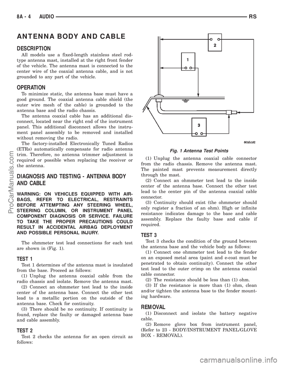
The ohmmeter test lead connections for each test
are shown in (Fig. 1).
TEST 1
Test 1 determines of the antenna mast is insulated
from the base. Proceed as follows:
(1) Unplug the antenna coaxial cable from the
radio chassis and isolate. Remove the antenna mast.
(2) Connect an ohmmeter test lead to the inside
center of the antenna base. Connect the other test
lead to a metallic portion on the outside of the
antenna base. Check for continuity.
(3) There should be no continuity. If continuity is
found, replace the faulty or damaged antenna base
and cable assembly.
TEST 2
Test 2 checks the antenna for an open circuit as
follows:(1) Unplug the antenna coaxial cable connector
from the radio chassis. Remove the antenna mast.
The painted mast prevents measurement directly
through the mast.
(2) Connect an ohmmeter test lead to the inside
center of the antenna base. Connect the other test
lead to the center pin of the antenna coaxial cable
connector.
(3) Continuity should exist (the ohmmeter should
only register a fraction of an ohm). High or infinite
resistance indicates damage to the base and cable
assembly. Replace the faulty base and cable if
required.
TEST 3
Test 3 checks the condition of the ground between
the antenna base and the vehicle body as follows:
(1) Connect one ohmmeter test lead to the fender
on an exposed metal area (paint and e-coat must be
penetrated to obtain continuity). Connect the other
test lead to the outer crimp on the antenna coaxial
cable connector.
(2) The resistance should be less than (1) ohm.
(3) If the resistance is more than (1) ohm, clean
and/or tighten the antenna base to the fender mount-
ing hardware.
REMOVAL
(1) Disconnect and isolate the battery negative
cable.
(2) Remove glove box from instrument panel,
(Refer to 23 - BODY/INSTRUMENT PANEL/GLOVE
BOX - REMOVAL).
Fig. 1 Antenna Test Points
8A - 4 AUDIORS
ProCarManuals.com