transmission removal CHRYSLER TOWN AND COUNTRY 2002 User Guide
[x] Cancel search | Manufacturer: CHRYSLER, Model Year: 2002, Model line: TOWN AND COUNTRY, Model: CHRYSLER TOWN AND COUNTRY 2002Pages: 2399, PDF Size: 57.96 MB
Page 287 of 2399
TRANSMISSION
TABLE OF CONTENTS
page page
TRANSMISSION
STANDARD PROCEDURE - FLUSHING
COOLERS AND TUBES.................38
TRANSMISSION OIL COOLER
DESCRIPTION.........................38
REMOVAL.............................38CLEANING............................39
INSPECTION..........................39
INSTALLATION.........................39
TRANSMISSION OIL COOLER LINES
REMOVAL.............................39
INSTALLATION.........................40
TRANSMISSION
STANDARD PROCEDURE - FLUSHING
COOLERS AND TUBES
The recommended procedure for cooler flushing is
to use Tool 6906 Cooler Flusher.
WARNING: WEAR PROTECTIVE EYEWEAR THAT
MEETS THE REQUIREMENTS OF OSHA AND ANSI
Z87.1±1968. WEAR STANDARD INDUSTRIAL RUB-
BER GLOVES. KEEP LIT CIGARETTES, SPARKS,
FLAMES, AND OTHER IGNITION SOURCES AWAY
FROM THE AREA TO PREVENT THE IGNITION OF
COMBUSTIBLE LIQUIDS AND GASES. KEEP A
CLASS (B) FIRE EXTINGUISHER IN THE AREA
WHERE THE FLUSHER WILL BE USED.
WARNING: KEEP THE AREA WELL VENTILATED.
DO NOT LET FLUSHING SOLVENT COME IN CON-
TACT WITH YOUR EYES OR SKIN: IF EYE CONTAM-
INATION OCCURS, FLUSH EYES WITH WATER FOR
15 TO 20 SECONDS. REMOVE CONTAMINATED
CLOTHING AND WASH AFFECTED SKIN WITH
SOAP AND WATER. SEEK MEDICAL ATTENTION.
(1) Remove cover plate filler plug on Tool 6906.
Fill reservoir 1/2 to 3/4 full of fresh flushing solution.
Use MopartTransmission Cooler Flush (MS-552) or
equivalent solution conforming to MS-552. Flushing
solvents are petroleum based solutions generally
used to clean automatic transmission components.
DO NOTuse solvents containing acids, water, gaso-
line, or any other corrosive liquids.
(2) Reinstall filler plug on Tool 6906.
(3) Verify pump power switch is turned OFF. Con-
nect red alligator clip to positive (+) battery post.
Connect black (-) alligator clip to a good ground.
NOTE: When flushing transmission cooler and
lines, ALWAYS reverse flush.(4) Connect the BLUE pressure line to the OUT-
LET (From) cooler line.
(5) Connect the CLEAR return line to the INLET
(To) cooler line
(6) Turn pump ON for two to three minutes to
flush cooler and lines.
(7) Turn pump OFF.
(8) Disconnect CLEAR suction line from reservoir
at cover plate. Disconnect CLEAR return line at
cover plate, and place it in a drain pan.
(9) Turn pump ON for 30 seconds to purge flush-
ing solution from cooler and lines. Turn pump OFF.
(10) Place CLEAR suction line into a one quart
container of MopartATF+4 (Automatic Transmission
FluidÐType 9602).
(11) Turn pump ON until all transmission fluid is
removed from the one quart container and lines. This
purges any residual cleaning solvent from the trans-
mission cooler and lines. Turn pump OFF.
(12) Disconnect alligator clips from battery. Recon-
nect flusher lines to cover plate, and remove flushing
adapters from cooler lines.
TRANSMISSION OIL COOLER
DESCRIPTION
The transmission oil cooler is an oil-to-air type
cooler that is mounted between the front of the radi-
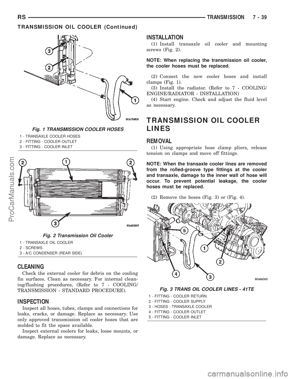
ator and back side of the A/C condenser (Fig. 2). Use
only approved transmission oil cooler hoses that are
molded to fit the space available.
REMOVAL
(1) Remove the radiator. (Refer to 7 - COOLING/
ENGINE/RADIATOR - REMOVAL)
(2) Disconnect lines from oil cooler (Fig. 1).
(3) Remove oil cooler attaching screws (Fig. 2).
(4) Remove the oil cooler.
7 - 38 TRANSMISSIONRS
ProCarManuals.com
Page 288 of 2399
CLEANING
Check the external cooler for debris on the cooling
fin surfaces. Clean as necessary. For internal clean-
ing/flushing procedures, (Refer to 7 - COOLING/
TRANSMISSION - STANDARD PROCEDURE).
INSPECTION
Inspect all hoses, tubes, clamps and connections for
leaks, cracks, or damage. Replace as necessary. Use
only approved transmission oil cooler hoses that are
molded to fit the space available.
Inspect external coolers for leaks, loose mounts, or
damage. Replace as necessary.
INSTALLATION
(1) Install transaxle oil cooler and mounting
screws (Fig. 2).
NOTE: When replacing the transmission oil cooler,
the cooler hoses must be replaced.
(2) Connect the new cooler hoses and install
clamps (Fig. 1).
(3) Install the radiator. (Refer to 7 - COOLING/
ENGINE/RADIATOR - INSTALLATION)
(4) Start engine. Check and adjust the fluid level
as necessary.
TRANSMISSION OIL COOLER
LINES
REMOVAL
(1) Using appropriate hose clamp pliers, release
tension on clamps and move off fittings.
NOTE: When the transaxle cooler lines are removed
from the rolled-groove type fittings at the cooler
and transaxle, damage to the inner wall of hose will
occur. To prevent potential leakage, the cooler
hoses must be replaced.
(2) Remove the hoses (Fig. 3) or (Fig. 4).
Fig. 1 TRANSMISSION COOLER HOSES
1 - TRANSAXLE COOLER HOSES
2 - FITTING - COOLER OUTLET
3 - FITTING - COOLER INLET
Fig. 2 Transmission Oil Cooler
1 - TRANSAXLE OIL COOLER
2 - SCREWS
3 - A/C CONDENSER (REAR SIDE)
Fig. 3 TRANS OIL COOLER LINES - 41TE
1 - FITTING - COOLER RETURN
2 - FITTING - COOLER SUPPLY
3 - HOSES - TRANSAXLE COOLER
4 - FITTING - COOLER OUTLET
5 - FITTING - COOLER INLET
RSTRANSMISSION7-39
TRANSMISSION OIL COOLER (Continued)
ProCarManuals.com
Page 338 of 2399

ELECTRONIC CONTROL MODULES
TABLE OF CONTENTS
page page
ELECTRONIC CONTROL MODULES
STANDARD PROCEDURE - PCM/SKIM
PROGRAMMING.......................2
ADJUSTABLE PEDAL MODULE
DIAGNOSIS AND TESTING - ADJUSTABLE
PEDAL MODULE.......................3
REMOVAL.............................3
INSTALLATION..........................3
BODY CONTROL MODULE
DESCRIPTION..........................3
OPERATION............................3
REMOVAL.............................5
INSTALLATION..........................5
CONTROLLER ANTILOCK BRAKE
DESCRIPTION..........................5
OPERATION............................5
REMOVAL.............................6
INSTALLATION..........................6
DATA LINK CONNECTOR
DESCRIPTION..........................7
OPERATION............................7
FRONT CONTROL MODULE
DESCRIPTION..........................7
OPERATION............................7
DIAGNOSIS AND TESTING - FRONT
CONTROL MODULE....................8
REMOVAL.............................8
INSTALLATION..........................8
HEATED SEAT MODULE
DESCRIPTION..........................9
OPERATION............................9
DIAGNOSIS AND TESTING - HEATED SEAT
MODULE.............................9
REMOVAL.............................10
INSTALLATION.........................10
POWER LIFTGATE MODULE
DESCRIPTION.........................10
OPERATION...........................10
REMOVAL.............................10
INSTALLATION.........................11
POWERTRAIN CONTROL MODULE
DESCRIPTION
DESCRIPTION........................11DIAGNOSTIC TROUBLE CODE...........13
OPERATION - SENSOR RETURN - PCM
INPUT..............................25
OPERATION - SCI RECEIVE - PCM INPUT . . 25
OPERATION - IGNITION SENSE - PCM
INPUT..............................25
OPERATION - PCM GROUND............25
OPERATION
OPERATION - 8-VOLT SUPPLY - PCM
OUTPUT............................25
OPERATION - 5 VOLT SUPPLY - PCM
OUTPUT............................25
STANDARD PROCEDURE - OBTAINING
DIAGNOSTIC TROUBLE CODES..........25
REMOVAL.............................26
INSTALLATION.........................26
SENTRY KEY IMMOBILIZER MODULE
DESCRIPTION.........................26
OPERATION...........................27
REMOVAL.............................27
INSTALLATION.........................27
TRANSMISSION CONTROL MODULE
DESCRIPTION.........................28
OPERATION...........................28
STANDARD PROCEDURE
STANDARD PROCEDURE - PINION
FACTOR SETTING.....................31
STANDARD PROCEDURE - QUICK LEARN
PROCEDURE........................31
REMOVAL.............................31
INSTALLATION.........................32
MEMORY SEAT/MIRROR MODULE
DESCRIPTION.........................33
OPERATION...........................33
DIAGNOSIS AND TESTING - MEMORY
SEAT/MIRROR MODULE................33
REMOVAL.............................33
INSTALLATION.........................33
SLIDING DOOR CONTROL MODULE
DESCRIPTION.........................33
OPERATION...........................34
REMOVAL.............................34
INSTALLATION.........................34
RSELECTRONIC CONTROL MODULES8E-1
ProCarManuals.com
Page 340 of 2399
(5) Obtain ignition keys to be programmed from
customer (8 keys maximum).
(6) Using the DRB III, erase all ignition keys by
selecting MISCELLANEOUS and ERASE ALL CUR-
RENT IGN. KEYS.
(7) Program all ignition keys.
Learned Key In Ignition - Ignition key transponder
ID is currently programmed in SKIM memory.
ADJUSTABLE PEDAL MODULE
DIAGNOSIS AND TESTING - ADJUSTABLE
PEDAL MODULE
Refer to Appropriate Diagnostic Information.
REMOVAL
(1) Remove adjustable pedal assembly from vehi-
cle. (Refer to 5 - BRAKES/HYDRAULIC/MECHANI-
CAL/PEDAL - REMOVAL)
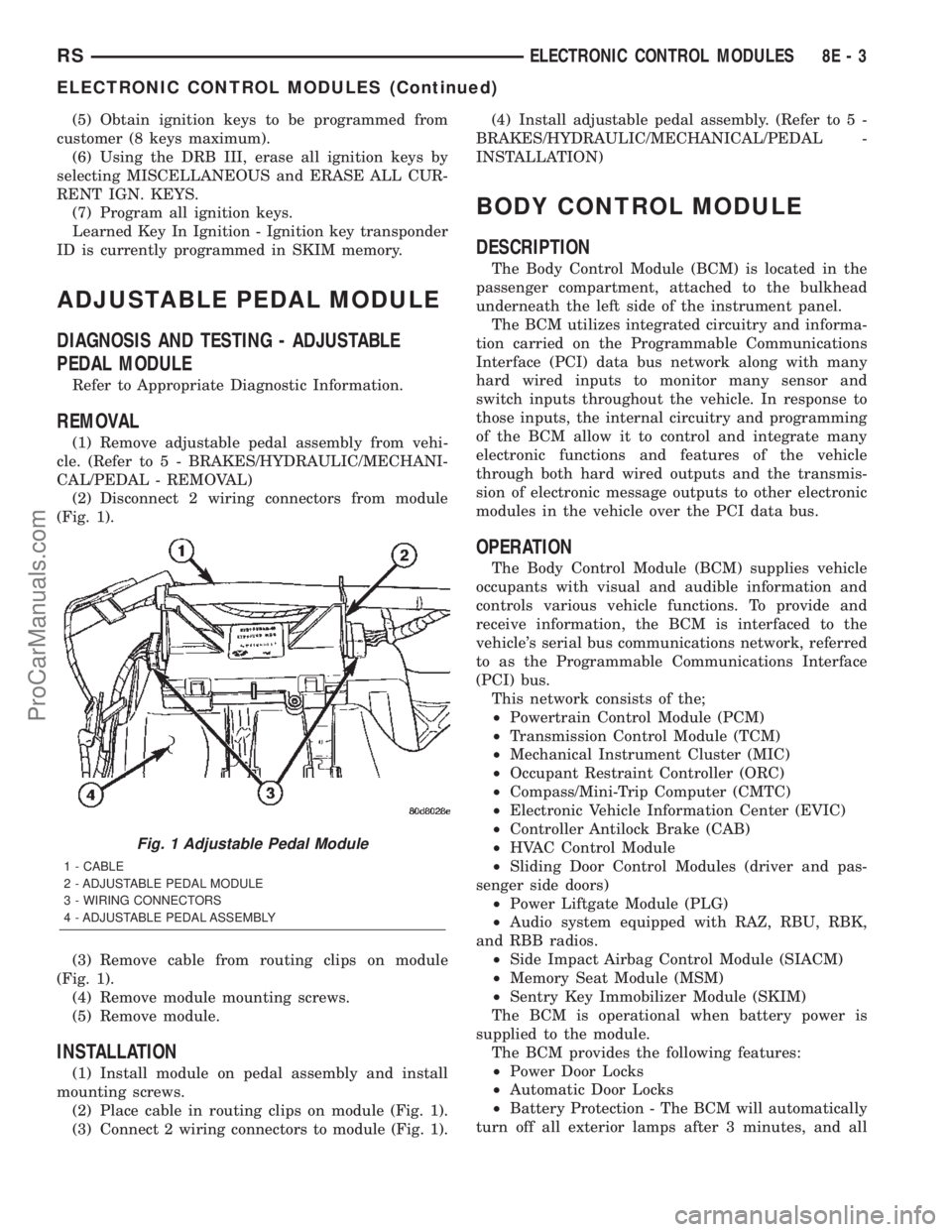
(2) Disconnect 2 wiring connectors from module
(Fig. 1).
(3) Remove cable from routing clips on module
(Fig. 1).
(4) Remove module mounting screws.
(5) Remove module.
INSTALLATION
(1) Install module on pedal assembly and install
mounting screws.
(2) Place cable in routing clips on module (Fig. 1).
(3) Connect 2 wiring connectors to module (Fig. 1).(4) Install adjustable pedal assembly. (Refer to 5 -
BRAKES/HYDRAULIC/MECHANICAL/PEDAL -
INSTALLATION)
BODY CONTROL MODULE
DESCRIPTION
The Body Control Module (BCM) is located in the
passenger compartment, attached to the bulkhead
underneath the left side of the instrument panel.
The BCM utilizes integrated circuitry and informa-
tion carried on the Programmable Communications
Interface (PCI) data bus network along with many
hard wired inputs to monitor many sensor and
switch inputs throughout the vehicle. In response to
those inputs, the internal circuitry and programming
of the BCM allow it to control and integrate many
electronic functions and features of the vehicle
through both hard wired outputs and the transmis-
sion of electronic message outputs to other electronic
modules in the vehicle over the PCI data bus.
OPERATION
The Body Control Module (BCM) supplies vehicle
occupants with visual and audible information and
controls various vehicle functions. To provide and
receive information, the BCM is interfaced to the
vehicle's serial bus communications network, referred
to as the Programmable Communications Interface
(PCI) bus.
This network consists of the;
²Powertrain Control Module (PCM)
²Transmission Control Module (TCM)
²Mechanical Instrument Cluster (MIC)
²Occupant Restraint Controller (ORC)
²Compass/Mini-Trip Computer (CMTC)
²Electronic Vehicle Information Center (EVIC)
²Controller Antilock Brake (CAB)
²HVAC Control Module
²Sliding Door Control Modules (driver and pas-
senger side doors)
²Power Liftgate Module (PLG)
²Audio system equipped with RAZ, RBU, RBK,
and RBB radios.
²Side Impact Airbag Control Module (SIACM)
²Memory Seat Module (MSM)
²Sentry Key Immobilizer Module (SKIM)
The BCM is operational when battery power is
supplied to the module.
The BCM provides the following features:
²Power Door Locks
²Automatic Door Locks
²Battery Protection - The BCM will automatically
turn off all exterior lamps after 3 minutes, and all
Fig. 1 Adjustable Pedal Module
1 - CABLE
2 - ADJUSTABLE PEDAL MODULE
3 - WIRING CONNECTORS
4 - ADJUSTABLE PEDAL ASSEMBLY
RSELECTRONIC CONTROL MODULES8E-3
ELECTRONIC CONTROL MODULES (Continued)
ProCarManuals.com
Page 347 of 2399

seat switch. Refer toDiagnosis and Testing
Heated Seat Switchin Heated Seats for heated
seat switch diagnosis and testing procedures. If the
heated seat switch checks OK, proceed as follows.
(1) Check the heated seat element (Refer to 8 -
ELECTRICAL/HEATED SEATS/HEATED SEAT
ELEMENT - DIAGNOSIS AND TESTING).
(2) Check the heated seat sensor (Refer to 8 -
ELECTRICAL/HEATED SEATS/HEATED SEAT
SENSOR - DIAGNOSIS AND TESTING).
(3) Check the heated seat switch (Refer to 8 -
ELECTRICAL/HEATED SEATS/DRIVER HEATED
SEAT SWITCH - DIAGNOSIS AND TESTING).
NOTE: Refer to Wiring for the location of complete
heated seat system wiring diagrams and connector
pin-out information.
(4) Using a voltmeter, backprobe the appropriate
heated seat module connector, do not disconnect.
Check for voltage at the appropriate pin cavities. 12v
should be present. If OK go to Step 5, if Not, Repair
the open or shorted voltage supply circuit as
required.
(5) Using a ohmmeter, backprobe the appropriate
heated seat module connector, do not disconnect.
Check for proper continuity to ground on the ground
pin cavities. Continuity should be present. If OK
replace the heated seat module with a known good
unit and retest system, if Not OK, Repair the open or
shorted ground circuit as required.
REMOVAL
(1) Disconnect and isolate the negative battery
cable.
(2) Remove the appropriate front seat from the
vehicle (Refer to 23 - BODY/SEATS/SEAT - REMOV-
AL).
(3) Unsnap the module from the seat cushion pan.
(4) Disconnect the module wire harness connec-
tors.
INSTALLATION
(1) Connect the module wire harness connectors.
(2) Snap the module on the seat cushion pan.
(3) Install the appropriate front seat in the vehicle
(Refer to 23 - BODY/SEATS/SEAT - INSTALLA-
TION).
(4) Connect and isolate the negative battery cable.
POWER LIFTGATE MODULE
DESCRIPTION
Vehicles equipped with a power liftgate (PLG) uti-
lize a PLG control module. This module is located on
the vehicles left side D-pillar just below the motorassembly (Fig. 9) and contains a microprocessor,
which is used to communicate to the vehicles body
control module. The PLG control module receives and
monitors logic inputs from all the PLG system
switches except for the outside handle switch. This
module also contains the software technology to
detect liftgate obstructions and stop and / or reverse
the door accordingly.
OPERATION
The PLG control module contains the electronic cir-
cuitry and software used to control the sequence of
events for the PLG system. This module comunicates
on the PCI bus circuit with the vehicles body control
module to monitor many different inputs and outputs
such as door lock status, transmission gear selector
position and vehicle speed. Refer to PLG system
operation for more information.
REMOVAL
(1) Disconnect and isolate the negative battery
cable.
(2) Remove left D-pillar trim panel from the vehi-
cle. Refer to Body for the procedure.
(3) Disconnect the wire harness connections from
the PLG motor assembly (Fig. 10).
Fig. 9 LIFTGATE CONTROL MODULE
1 - POWER LIFTGATE CONTROL MODULE
2 - MODULE RETAINING SCREWS
3 - D-PILLAR
4 - POWER LIFTGATE MOTOR
5 - MODULE ELECTRICAL CONNECTORS
8E - 10 ELECTRONIC CONTROL MODULESRS
HEATED SEAT MODULE (Continued)
ProCarManuals.com
Page 368 of 2399

STANDARD PROCEDURE
STANDARD PROCEDURE - PINION FACTOR
SETTING
NOTE: This procedure must be performed if the
Transmission Control Module (TCM) has been
replaced with a NEW or replacement unit. Failure to
perform this procedure will result in an inoperative
or improperly calibrated speedometer.
The vehicle speed readings for the speedometer are
taken from the output speed sensor. The TCM must
be calibrated to the different combinations of equip-
ment (final drive and tires) available. Pinion Factor
allows the technician to set the Transmission Control
Module initial setting so that the speedometer read-
ings will be correct. To properly read and/or reset the
Pinion Factor, it is necessary to use a DRBIIItscan
tool.
(1) Plug the DRBIIItscan tool into the diagnostic
connector located under the instrument panel.
(2) Select the Transmission menu.
(3) Select the Miscellaneous menu.
(4) Select Pinion Factor. Then follow the instruc-
tions on the DRBIIItscan tool screen.
STANDARD PROCEDURE - QUICK LEARN
PROCEDURE
The quick learn procedure requires the use of the
DRBIIItscan tool. This program allows the elec-
tronic transaxle system to recalibrate itself. This will
provide the best possible transaxle operation.
NOTE: The quick learn procedure should be per-
formed if any of the following procedures are per-
formed:
²Transaxle Assembly Replacement
²Transmission Control Module Replacement
²Solenoid/Pressure Switch Assembly Replacement
²Clutch Plate and/or Seal Replacement
²Valve Body Replacement or Recondition
To perform the Quick Learn Procedure, the follow-
ing conditions must be met:
²The brakes must be applied
²The engine speed must be above 500 rpm
²The throttle angle (TPS) must be less than 3
degrees
²The shift lever position must stay until
prompted to shift to overdrive
²The shift lever position must stay in overdrive
after the Shift to Overdrive prompt until the
DRBIIItindicates the procedure is complete
²The calculated oil temperature must be above
60É and below 200É(1) Plug the DRBIIItscan tool into the diagnostic
connector. The connector is located under the instru-
ment panel.
(2) Go to the Transmission screen.
(3) Go to the Miscellaneous screen.
(4) Select Quick Learn Procedure. Follow the
instructions of the DRBIIItto perform the Quick
Learn Procedure.
REMOVAL
NOTE: If transmission control module is being
replaced with a new or replacement unit, the Pinion
Factor and Quick Learn procedures must be per-
formed. (Refer to 8 - ELECTRICAL/ELECTRONIC
CONTROL MODULES/TRANSMISSION CONTROL
MODULE - STANDARD PROCEDURE) (Refer to 8 -
ELECTRICAL/ELECTRONIC CONTROL MODULES/
TRANSMISSION CONTROL MODULE - STANDARD
PROCEDURE)
(1) Disconnect battery negative cable.
(2) Raise vehicle on hoist.
(3) Remove left front tire/wheel assembly.
(4) Pull back splash shield to gain access to TCM
location.
(5) Disconnect TCM 60-way connector (Fig. 16).
Fig. 16 Transmission Control Module 60-way
Connector
1 - TRANSMISSION CONTROL MODULE (TCM)
2 - 60-WAY CONNECTOR
RSELECTRONIC CONTROL MODULES8E-31
ProCarManuals.com
Page 369 of 2399

(6) Remove three (3) TCM-to-rail screws and
remove TCM from vehicle (Fig. 17).
INSTALLATION
NOTE: If transmission control module is being
replaced with a new or replacement unit, the Pinion
Factor and Quick Learn procedures must be per-
formed. (Refer to 8 - ELECTRICAL/ELECTRONIC
CONTROL MODULES/TRANSMISSION CONTROL
MODULE - STANDARD PROCEDURE) (Refer to 8 -
ELECTRICAL/ELECTRONIC CONTROL MODULES/
TRANSMISSION CONTROL MODULE - STANDARD
PROCEDURE)
(1) Install TCM into position (Fig. 18). Install
three (3) screws and torque to 3 N´m (30 in. lbs.).
(2) Install TCM harness 60±way connector (Fig.
19) and torque to 4 N´m (35 in. lbs.).
(3) Install splash shield into position with fasten-
ers.
(4) Install left front wheel/tire assembly.
(5) Lower vehicle.
(6) Connect battery negative cable.
(7) If TCM was replaced, reset Pinion Factor and
Quick Learn. (Refer to 8 - ELECTRICAL/ELEC-
TRONIC CONTROL MODULES/TRANSMISSION
CONTROL MODULE - STANDARD PROCEDURE)
(Refer to 8 - ELECTRICAL/ELECTRONIC CON-
TROL MODULES/TRANSMISSION CONTROL
MODULE - STANDARD PROCEDURE).
Fig. 17 Transmission Control Module Removal/
Installation
1 - SCREW
2 - TRANSMISSION CONTROL MODULE (TCM)
3 - CLIP
4 - LEFT RAIL
Fig. 18 Transmission Control Module Removal/
Installation
1 - SCREW
2 - TRANSMISSION CONTROL MODULE (TCM)
3 - CLIP
4 - LEFT RAIL
Fig. 19 Transmission Control Module 60-way
Connector
1 - TRANSMISSION CONTROL MODULE (TCM)
2 - 60-WAY CONNECTOR
8E - 32 ELECTRONIC CONTROL MODULESRS
TRANSMISSION CONTROL MODULE (Continued)
ProCarManuals.com
Page 370 of 2399
MEMORY SEAT/MIRROR
MODULE
DESCRIPTION
Vehicles equipped with the memory seat/mirror
option, utilize a memory module located under the
drivers front seat. This module is basically wired in-
line between the power seat switch and the power
seat track/adjuster motors, or in-line between the
power mirror switch and the power side view mir-
ror(s) motor(s). The MSMM contains a central pro-
cessing unit that communicates with other modules
on the Programmable Communications Interface
(PCI) data bus network.
The Memory Seat/Mirror Module (MSMM) receives
hard wired inputs from the driver power seat switch
and the potentiometers on each of the driver side
power seat track motors, or from the power mirror
switch and the potentiometers on the side view mir-
ror. The MSMM receives messages over the PCI data
bus from the Body Control Module (BCM) (memory
switch status), the Powertrain Control Module (PCM)
(vehicle speed status). The MSMM will prevent the
seat memory recall function from being initiated if
the driver side seat belt is buckled, if the transmis-
sion gear selector lever is not in the Park or Neutral
positions, or if the vehicle is moving.
For diagnosis of the MSMM or the PCI data bus, a
DRB IIItscan tool and the proper Diagnostic Proce-
dures manual are recommended. The MSMM cannot
be repaired and, if faulty or damaged, it must be
replaced. Refer toMemory Systemin the Power
Seat or Power Mirror section of this manual for more
information on the memory system option.
OPERATION
When memory system operation is requested
(depressing of the memory switch), a resistor multi-
plexed signal is sent from the memory switch to the
body control module (BCM). The body control module
will then send the appropriate signals out to the
memory/mirror seat module, the memory/mirror seat
module then applies the voltage supply to the power
seat track or side-view mirror if the proper require-
ments are met. The vehicle speed must equal zero
and the transmission must be in park or neutral in
order for the memory system to function.
DIAGNOSIS AND TESTING - MEMORY
SEAT/MIRROR MODULE
Visually inspect the related wiring harness connec-
tors. Look for broken, bent, pushed out, or corroded
terminals. If any of the above conditions are present,
repair as necessary. If not, use a DRB IIItscan tool
and the proper Diagnostic Procedures Manual to testthe memory/mirror seat module. For complete circuit
diagrams, refer toWiring Diagrams.
REMOVAL
(1) Disconnect and isolate the battery negative
cable.
(2) Remove the driver side front bucket seat
retaining nuts from under the vehicle (Refer to 23 -
BODY/SEATS/SEAT - REMOVAL).
(3) Lift the drivers seat up and out of the mount-
ing holes in the floor pan and lay the seat rearward
to access the module located under the seat. It is not
necessary to disconnect the seat electrical, just use
care not to damage the wiring by over-extending.
(4) Disconnect the memory/mirror seat module
electrical connectors. Depress the retaining tab and
pull straight apart.
(5) Remove the module retaining bolts and remove
the module from the bracket.
INSTALLATION
(1) Position and install the module retaining bolts.
(2) Connect the memory/mirror seat module elec-
trical connectors.
(3) Position the drivers seat in the mounting holes
in the floor pan.
(4) Install the driver side front bucket seat retain-
ing nuts from under the vehicle (Refer to 23 - BODY/
SEATS/SEAT - INSTALLATION).
(5) Connect the battery negative cable.
SLIDING DOOR CONTROL
MODULE
DESCRIPTION
Vehicles equipped with a power sliding door utilize
a sliding door control module. The sliding door con-
trol module is located behind the sliding door trim
panel in the center of the door, just above the sliding
door motor (Fig. 20). This module controls the opera-
tion of the door through the Programmable Commu-
nication Interface (PCI) J1850 data bus circuit and
the Body Control Module. The sliding door control
module contains software technology which enables it
to detect resistance to door travel and to reverse door
travel in order to avoid damage to the door or to
avoid possible personal injury if the obstruction is a
person. This feature functions in both the opening
and closing cycles. If the power sliding door system
develops any problems the control module will store
and recall Diagnostic Trouble Codes (DTC). The use
of a diagnostic scan tool, such as the DRB IIItis
required to read and troubleshoot these trouble
codes. The sliding door control module can be
RSELECTRONIC CONTROL MODULES8E-33
ProCarManuals.com
Page 403 of 2399
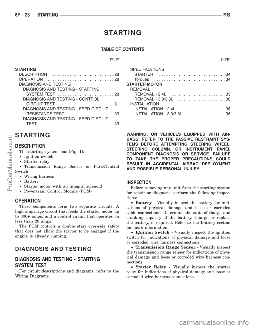
STARTING
TABLE OF CONTENTS
page page
STARTING
DESCRIPTION.........................28
OPERATION...........................28
DIAGNOSIS AND TESTING
DIAGNOSIS AND TESTING - STARTING
SYSTEM TEST.......................28
DIAGNOSIS AND TESTING - CONTROL
CIRCUIT TEST........................31
DIAGNOSIS AND TESTING - FEED CIRCUIT
RESISTANCE TEST....................33
DIAGNOSIS AND TESTING - FEED CIRCUIT
TEST...............................33SPECIFICATIONS
STARTER ...........................34
Torques.............................34
STARTER MOTOR
REMOVAL
REMOVAL - 2.4L......................35
REMOVAL - 3.3/3.8L...................36
INSTALLATION
INSTALLATION - 2.4L..................36
INSTALLATION - 3.3/3.8L................36
STARTING
DESCRIPTION
The starting system has (Fig. 1):
²Ignition switch
²Starter relay
²Transmission Range Sensor or Park/Neutral
Switch
²Wiring harness
²Battery
²Starter motor with an integral solenoid
²Powertrain Control Module (PCM)
OPERATION
These components form two separate circuits. A
high amperage circuit that feeds the starter motor up
to 300+ amps, and a control circuit that operates on
less than 20 amps.
The PCM controls a double start over-ride safety
that does not allow the starter to be engaged if the
engine is already running.
DIAGNOSIS AND TESTING
DIAGNOSIS AND TESTING - STARTING
SYSTEM TEST
For circuit descriptions and diagrams, refer to the
Wiring Diagrams.WARNING: ON VEHICLES EQUIPPED WITH AIR-
BAGS, REFER TO THE PASSIVE RESTRAINT SYS-
TEMS BEFORE ATTEMPTING STEERING WHEEL,
STEERING COLUMN, OR INSTRUMENT PANEL
COMPONENT DIAGNOSIS OR SERVICE. FAILURE
TO TAKE THE PROPER PRECAUTIONS COULD
RESULT IN ACCIDENTAL AIRBAG DEPLOYMENT
AND POSSIBLE PERSONAL INJURY.
INSPECTION
Before removing any unit from the starting system
for repair or diagnosis, perform the following inspec-
tions:
²Battery- Visually inspect the battery for indi-
cations of physical damage and loose or corroded
cable connections. Determine the state-of-charge and
cranking capacity of the battery. Charge or replace
the battery, if required. Refer to the Battery section
for more information.
²Ignition Switch- Visually inspect the ignition
switch for indications of physical damage and loose
or corroded wire harness connections.
²Transmission Range Sensor- Visually inspect
the transmission range sensor for indications of phys-
ical damage and loose or corroded wire harness con-
nections.
²Starter Relay- Visually inspect the starter
relay for indications of physical damage and loose or
corroded wire harness connections.
8F - 28 STARTINGRS
ProCarManuals.com
Page 409 of 2399
(3) To disable the ignition and fuel systems, dis-
connect the Automatic Shutdown Relay (ASD). The
ASD relay is located in the Power Distribution Cen-
ter (PDC). Refer to the PDC cover for proper relay
location.
(4) Verify that all lights and accessories are OFF,
and the transmission shift selector is in the PARK
and SET parking brake.
CAUTION: Do not overheat the starter motor or
draw the battery voltage below 9.6 volts during
cranking operations.
(5) Rotate and hold the ignition switch in the
START position. Observe the volt-ampere tester (Fig.
3).
²If voltage reads above 9.6 volts, and amperage
draw reads above 280 amps, check for engine seizing
or faulty starter.
²If voltage reads 12.4 volts or greater and amper-
age reads 0 to 10 amps, check for corroded cables
and/or bad connections.
²Voltage below 9.6 volts and amperage draw
above 300 amps, the problem is the starter. Replace
the starter refer to starter removal.
(6) After the starting system problems have been
corrected, verify the battery state-of-charge and
charge battery if necessary. Disconnect all testing
equipment and connect ASD relay. Start the vehicle
several times to assure the problem has been cor-
rected.SPECIFICATIONS
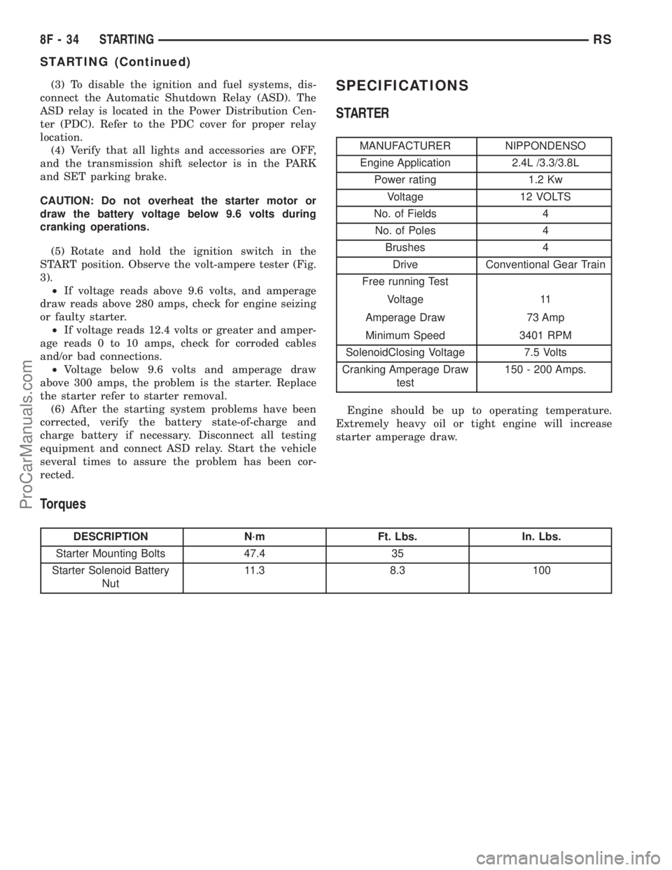
STARTER
MANUFACTURER NIPPONDENSO
Engine Application 2.4L /3.3/3.8L
Power rating 1.2 Kw
Voltage 12 VOLTS
No. of Fields 4
No. of Poles 4
Brushes 4
Drive Conventional Gear Train
Free running Test
Voltage 11
Amperage Draw 73 Amp
Minimum Speed 3401 RPM
SolenoidClosing Voltage 7.5 Volts
Cranking Amperage Draw
test150 - 200 Amps.
Engine should be up to operating temperature.
Extremely heavy oil or tight engine will increase
starter amperage draw.
Torques
DESCRIPTION N´m Ft. Lbs. In. Lbs.
Starter Mounting Bolts 47.4 35
Starter Solenoid Battery
Nut11.3 8.3 100
8F - 34 STARTINGRS
STARTING (Continued)
ProCarManuals.com