liftgate CHRYSLER TOWN AND COUNTRY 2002 Owner's Guide
[x] Cancel search | Manufacturer: CHRYSLER, Model Year: 2002, Model line: TOWN AND COUNTRY, Model: CHRYSLER TOWN AND COUNTRY 2002Pages: 2399, PDF Size: 57.96 MB
Page 556 of 2399
OPERATION
On the power cinch/release latch, the latch
mounted actuator provides the torque required to
close the power liftgate from the secondary to the pri-
mary closed and latched position. On the power
cinch/release latch and the power release only latch,
the actuator releases the liftgate from the primary
closed and latched position to the fully unlatched and
movable position.
REMOVAL
(1) Open the hood, disconnect and isolate the neg-
ative battery cable.
(2) Open the liftgate and remove the liftgate trim
panel. Refer to Body for the procedure.
(3) Disconnect the power latch electrical connector
(Fig. 12).
(4) Remove the power latch retaining bolts.
(5) Disconnect the liftgate lock cylinder link rod
from the key cylinder or latch assembly. To discon-
nect from latch, rotate the plastic retaining clip 90 É
to unsnap clip from linkrod. Then pull link rod
straight out of latch arm.
INSTALLATION
(1) Connect the liftgate lock cylinder link rod on
the cinch latch assembly. Rotate the plastic retaining
clip 90 É to lock retaining clip on linkrod.
(2) Connect the link rod on the lock cylinder.
(3) Install the power latch retaining bolts. Torque
to 10 N´m (90 in. lbs.).
(4) Connect the power latch electrical connector
and secure push pin retainers.
(5) Connect the negative battery cable.
(6) Using an appropriate scan tool, check and
erase any power liftgate control module diagnostic
trouble codes related to the power latch.
(7) Verify power liftgate system and power cinch /
release latch operation. Cycle the power liftgate
through one complete open and close cycle, this will
allow the power liftgate control module to relearn its
cycle with the new components.
(8) Verify power liftgate manual operation. Using
liftgate key rotate the lock cylinder to verify door
operation. Pull door open using exterior liftgate han-
dle / switch.
(9) Install the liftgate trim panel. Refer to Body for
the procedure.
LATCH ACTUATOR
DESCRIPTION
Vehicles equipped with a power liftgate utilize a
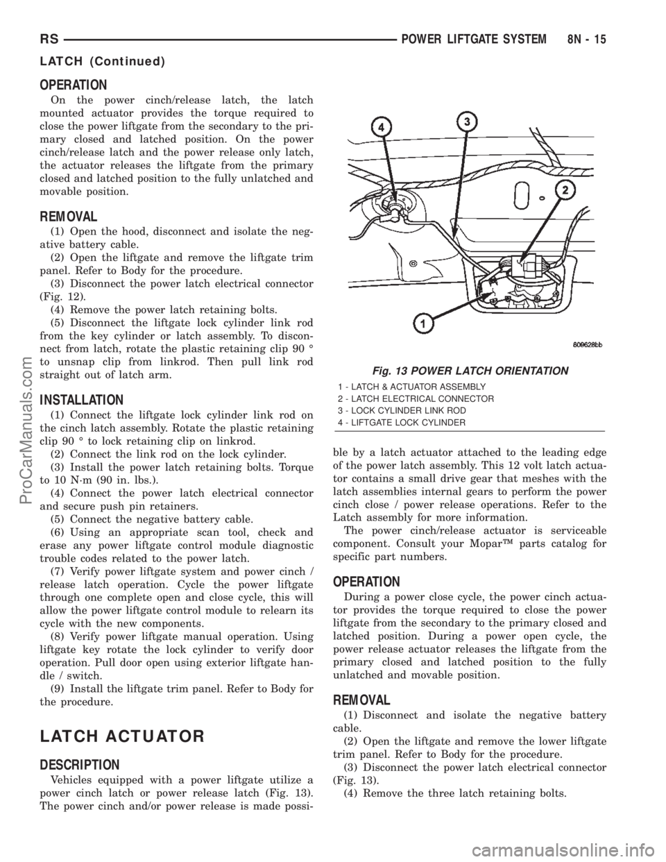
power cinch latch or power release latch (Fig. 13).
The power cinch and/or power release is made possi-ble by a latch actuator attached to the leading edge
of the power latch assembly. This 12 volt latch actua-
tor contains a small drive gear that meshes with the
latch assemblies internal gears to perform the power
cinch close / power release operations. Refer to the
Latch assembly for more information.
The power cinch/release actuator is serviceable
component. Consult your MoparŸ parts catalog for
specific part numbers.
OPERATION
During a power close cycle, the power cinch actua-
tor provides the torque required to close the power
liftgate from the secondary to the primary closed and
latched position. During a power open cycle, the
power release actuator releases the liftgate from the
primary closed and latched position to the fully
unlatched and movable position.
REMOVAL
(1) Disconnect and isolate the negative battery
cable.
(2) Open the liftgate and remove the lower liftgate
trim panel. Refer to Body for the procedure.
(3) Disconnect the power latch electrical connector
(Fig. 13).
(4) Remove the three latch retaining bolts.
Fig. 13 POWER LATCH ORIENTATION
1 - LATCH & ACTUATOR ASSEMBLY
2 - LATCH ELECTRICAL CONNECTOR
3 - LOCK CYLINDER LINK ROD
4 - LIFTGATE LOCK CYLINDER
RSPOWER LIFTGATE SYSTEM8N-15
LATCH (Continued)
ProCarManuals.com
Page 557 of 2399
(5) Grab the latch assembly and unhook the key
cylinder link rod from the key cylinder (Fig. 13).
(6) Place the latch assembly on a bench and locate
the three wires leading from the actuator portion of
the latch assembly.
(7) Disengage the main connector retaining push
pins from the latch actuator housing.
(8) Back the three wires out of the main latch elec-
trical connector. Refer to the wiring section of the
service manual for detailed instructions.
(9) Flip the latch assembly over and remove the
latch actuator retaining screw(s).
(10) Remove the latch actuator from the latch
assembly.
INSTALLATION
(1) Install the latch actuator on the latch assem-
bly.
(2) Install the three latch actuator retaining
screws. Torque the screws to 4 in. lbs.
(3) Install the three wires in the main latch elec-
trical connector. Refer to the wiring section of the
service manual for detailed instructions.
NOTE: Be certain wires are reinstalled in the correct
wire cavities. Failure to do so could result in dam-
age to the latch actuator. Refer to Wiring Diagrams
if previous notes were not made.
(4) Secure the main connector retaining push pins
on the latch actuator housing.
(5) Grab the latch assembly and hook the key cyl-
inder link rod on the key cylinder.
(6) Position the latch and install the three latch
retaining bolts. Torque to 10 N´m (90 in. lbs.).
(7) Connect the power latch electrical connector.
(8) Install the lower liftgate trim panel. Refer to
Body for the procedure.
(9) Connect the negative battery cable.
EXTERIOR HANDLE SWITCH
DESCRIPTION
Vehicles equipped with a power liftgate or power
locks utilize a exterior handle switch. The exterior
handle switch is a electronic release switch mounted
to the rear license plate lamp housing assembly,
located just above the license plate. This switch con-
trols the power liftgate release function and is also
capable of reversing the power liftgate when it is in
motion. A full power open cycle cannot be performed
using this switch, only one of the power open com-
mand switches (key fob and overhead console
mounted) can be used to perform a full power open
cycle.The exterior handle switch is a serviceable compo-
nent. Consult your MoparŸ parts catalog for a spe-
cific part number.
OPERATION
When the exterior handle switch is depressed, with
the liftgate in the closed position. A message is sent
to the Body Control Module (BCM). The Body Con-
trol Module then sends a signal to the power liftgate
control module via the J1850 PCI data bus circuit.
The power liftgate control module then sends a sig-
nal to the power latch mounted actuator, which
moves the liftgate from the primary closed and
latched position to the open and movable position. If
the liftgate is not pulled open once the latch releases
within a few seconds, the latch will cinch closed
again.
REMOVAL
(1) Disconnect and isolate the negative battery
cable.
(2) Open the liftgate and remove the liftgate trim
panel. Refer to the Body section of the service man-
ual for the procedure.
(3) Remove the rear lamp bar assembly from the
vehicle. Refer to the Body section of the service man-
ual for the procedure.
(4) Locate the two wires going to the exterior han-
dle switch. Cut the tie strap and trace the wires to
the large electrical connector and back the wires out
of the large connector and through the grommet.
Refer to the Wiring section of the service manual for
detailed instructions.
(5) Depress the two exterior handle switch retain-
ing tabs and roll the switch out of the light bar
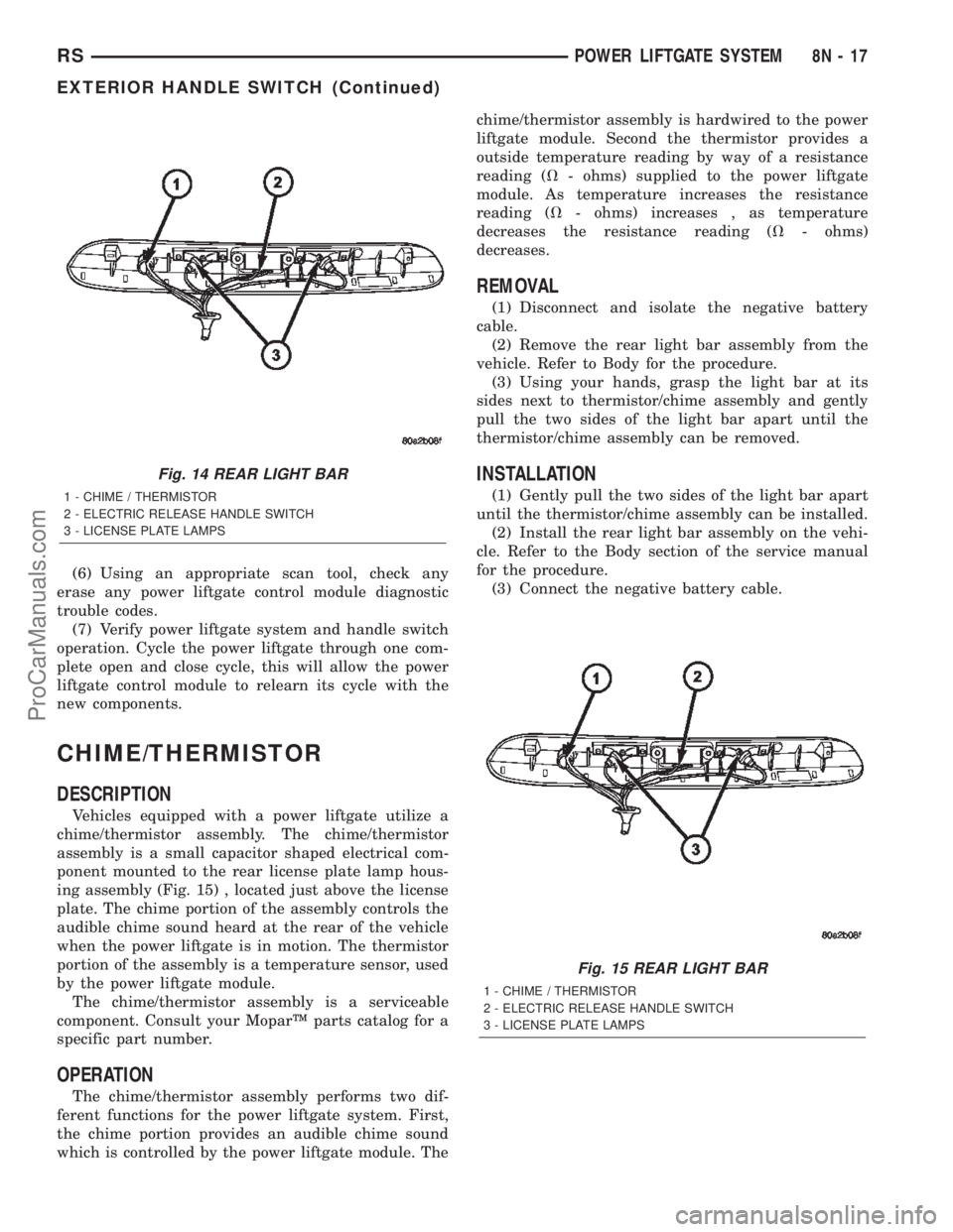
assembly (Fig. 14).
INSTALLATION
(1) Install the handle switch in the light bar
assembly.
(2) Locate the two wires going to the exterior han-
dle switch. Install the wires through the grommet
and in the large connector. Secure with a tie strap.
Refer to the Wiring section of the service manual for
detailed instructions.
NOTE: Be certain wires are reinstalled in the correct
wire cavities. Failure to do so could result in dam-
age to the handle switch. Refer to Wiring Diagrams
if previous notes were not made.
(3) Install the rear light bar. Refer to the Body sec-
tion of the service manual for the procedure.
(4) Install the liftgate trim panel. Refer to the
Body section of the service manual for the procedure.
(5) Connect the negative battery cable.
8N - 16 POWER LIFTGATE SYSTEMRS
LATCH ACTUATOR (Continued)
ProCarManuals.com
Page 558 of 2399
(6) Using an appropriate scan tool, check any
erase any power liftgate control module diagnostic
trouble codes.
(7) Verify power liftgate system and handle switch
operation. Cycle the power liftgate through one com-
plete open and close cycle, this will allow the power
liftgate control module to relearn its cycle with the
new components.
CHIME/THERMISTOR
DESCRIPTION
Vehicles equipped with a power liftgate utilize a
chime/thermistor assembly. The chime/thermistor
assembly is a small capacitor shaped electrical com-
ponent mounted to the rear license plate lamp hous-
ing assembly (Fig. 15) , located just above the license
plate. The chime portion of the assembly controls the
audible chime sound heard at the rear of the vehicle
when the power liftgate is in motion. The thermistor
portion of the assembly is a temperature sensor, used
by the power liftgate module.
The chime/thermistor assembly is a serviceable
component. Consult your MoparŸ parts catalog for a
specific part number.
OPERATION
The chime/thermistor assembly performs two dif-
ferent functions for the power liftgate system. First,
the chime portion provides an audible chime sound
which is controlled by the power liftgate module. Thechime/thermistor assembly is hardwired to the power
liftgate module. Second the thermistor provides a
outside temperature reading by way of a resistance
reading (V- ohms) supplied to the power liftgate
module. As temperature increases the resistance
reading (V- ohms) increases , as temperature
decreases the resistance reading (V- ohms)
decreases.
REMOVAL
(1) Disconnect and isolate the negative battery
cable.
(2) Remove the rear light bar assembly from the
vehicle. Refer to Body for the procedure.
(3) Using your hands, grasp the light bar at its
sides next to thermistor/chime assembly and gently
pull the two sides of the light bar apart until the
thermistor/chime assembly can be removed.
INSTALLATION
(1) Gently pull the two sides of the light bar apart
until the thermistor/chime assembly can be installed.
(2) Install the rear light bar assembly on the vehi-
cle. Refer to the Body section of the service manual
for the procedure.
(3) Connect the negative battery cable.
Fig. 14 REAR LIGHT BAR
1 - CHIME / THERMISTOR
2 - ELECTRIC RELEASE HANDLE SWITCH
3 - LICENSE PLATE LAMPS
Fig. 15 REAR LIGHT BAR
1 - CHIME / THERMISTOR
2 - ELECTRIC RELEASE HANDLE SWITCH
3 - LICENSE PLATE LAMPS
RSPOWER LIFTGATE SYSTEM8N-17
EXTERIOR HANDLE SWITCH (Continued)
ProCarManuals.com
Page 560 of 2399
referred to, is an open and close command switch
located on the vehicles interior body side B-pillar
trim. The overhead console switch, is an open and
close command switch located in the vehicle's over-
head console. More detailed information can be found
on these components later in this section.
Safety is of the utmost concern with the power
sliding door system. Software technology has enabled
the power sliding door control module to detect resis-
tance to door travel. This allows the power sliding
door to stop and reverse direction any time an
obstruction is felt or any of the command switches
are operated (while closing only). Battery voltage is
supplied to the power sliding door system through a
40 amp fuse, located in the Intelligent Power Module
(IPM) assembly (Fig. 3). The child lockout switch pre-
vents children from opening or actuating the power
sliding door system when desired. In the unlikely
event that the power sliding door system develops a
fault, the power sliding door can still be operated
manually from the interior or exterior door handle,
just like a standard manual sliding door.
The power sliding door control module communi-
cates on the J1850 PCI Data Bus Circuit. Therefore,
the power sliding door control module can generate
and store its own diagnostic trouble codes (DTC). A
diagnostic scan tool, such as the DRB IIItis used to
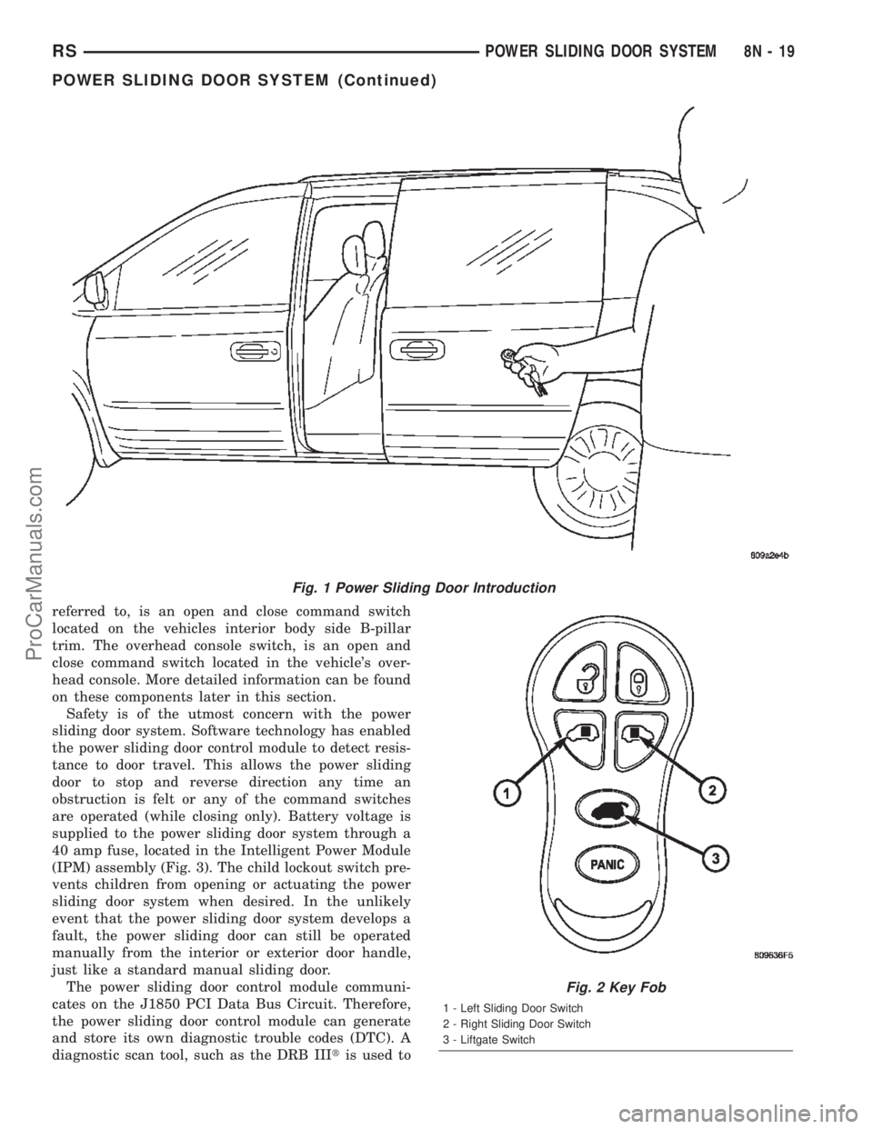
Fig. 1 Power Sliding Door Introduction
Fig. 2 Key Fob
1 - Left Sliding Door Switch
2 - Right Sliding Door Switch
3 - Liftgate Switch
RSPOWER SLIDING DOOR SYSTEM8N-19
POWER SLIDING DOOR SYSTEM (Continued)
ProCarManuals.com
Page 580 of 2399
POWER LOCKS
TABLE OF CONTENTS
page page
POWER LOCKS
DESCRIPTION.........................39
OPERATION...........................40
DOOR CYLINDER LOCK SWITCH
DESCRIPTION.........................41
OPERATION...........................41
DIAGNOSIS AND TESTING - DOOR
CYLINDER LOCK SWITCH..............41
REMOVAL.............................42
INSTALLATION.........................42
DOOR LOCK MOTOR
DIAGNOSIS AND TESTING - DOOR LOCK
MOTOR .............................42
DOOR LOCK SWITCH
DIAGNOSIS AND TESTING - DOOR LOCK
SWITCH............................42
REMOVAL.............................43
INSTALLATION.........................43
KEYLESS ENTRY TRANSMITTER
STANDARD PROCEDURE
STANDARD PROCEDURE - HORN CHIRP
PREFERENCE........................43STANDARD PROCEDURE - BATTERY
REPLACEMENT.......................43
SPECIFICATIONS
RANGE.............................43
BATTERY...........................43
REMOTE KEYLESS ENTRY MODULE
DESCRIPTION.........................44
OPERATION...........................44
DIAGNOSIS AND TESTING - REMOTE
KEYLESS ENTRY MODULE..............44
STANDARD PROCEDURE - PROGRAMMING
RKE MODULE........................44
REMOVAL.............................44
INSTALLATION.........................45
SLIDING DOOR LOCK MOTOR
REMOVAL.............................45
INSTALLATION.........................45
POWER LOCKS
DESCRIPTION
POWER DOOR LOCK SYSTEM
The front doors, sliding door(s) and liftgate are
equipped with actuator motors to lock or unlock the
latch mechanisms. The door lock actuator motor is
not serviced separately from the door latch, except
for the sliding door(s).
AUTOMATIC DOOR LOCK
The vehicle comes with two options for power door
locks:
²Rolling automatic lock (ENABLE), doors auto-
matically lock at approximately at 25.7 Km/h (16
mph).
²No rolling automatic lock (DISABLE), doors do
not automatically lock when the vehicle is moving.
AUTOMATIC DOOR UNLOCK
The doors will unlock automatically on vehicles
equipped with power door locks if:
²Auto door locks feature is enabled and automatic
unlock is enabled.²The transmission was in gear and speed is above
zero.
²The transmission in park or neutral and speed
is zero.
²Any door (excluding liftgate) opens.
DOOR LOCK INHIBIT
The BCM cancels out the door lock switch actua-
tion, when the key is in the Ignition Switch and
either front door is open.
Pressing the key fob RKE lock/unlock under these
conditions results in normal lock/unlock activation.
CENTRAL LOCKING
If equipped with Vehicle Theft Security System
(VTSS), all the doors can be locked with the key by
using any of the door lock cylinders. Turning the key
to the lock position will lock all the doors.
DOOR LOCK CIRCUIT PROTECTION
The door lock system is protected by a 40 amp fuse
located in the IPM. The BCM receives lock/unlock
input and will turn on the appropriate drivers and
provide a voltage level to the door lock motor for a
specific time. The IPM is located along the side of the
vehicle battery in the engine compartment.
RSPOWER LOCKS8N-39
ProCarManuals.com
Page 581 of 2399
REMOTE KEYLESS ENTRY SYSTEM
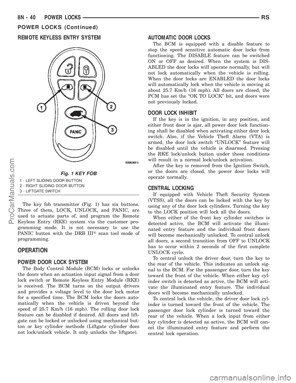
The key fob transmitter (Fig. 1) has six buttons.
Three of them, LOCK, UNLOCK, and PANIC, are
used to actuate parts of, and program the Remote
Keyless Entry (RKE) system via the customer pro-
gramming mode. It is not necessary to use the
PANIC button with the DRB IIItscan tool mode of
programming.
OPERATION
POWER DOOR LOCK SYSTEM
The Body Control Module (BCM) locks or unlocks
the doors when an actuation input signal from a door
lock switch or Remote Keyless Entry Module (RKE)
is received. The BCM turns on the output drivers
and provides a voltage level to the door lock motor
for a specified time. The BCM locks the doors auto-
matically when the vehicle is driven beyond the
speed of 25.7 Km/h (16 mph). The rolling door lock
feature can be disabled if desired. All doors and lift-
gate can be locked or unlocked using mechanical but-
ton or key cylinder methods (Liftgate cylinder does
not lock/unlock vehicle. It only unlocks the liftgate).
AUTOMATIC DOOR LOCKS
The BCM is equipped with a disable feature to
stop the speed sensitive automatic door locks from
functioning. The DISABLE feature can be switched
ON or OFF as desired. When the system is DIS-
ABLED the door locks will operate normally, but will
not lock automatically when the vehicle is rolling.
When the door locks are ENABLED the door locks
will automatically lock when the vehicle is moving at
about 25.7 Km/h (16 mph). All doors are closed, the
PCM has set the ªOK TO LOCKº bit, and doors were
not previously locked.
DOOR LOCK INHIBIT
If the key is in the ignition, in any position, and
either front door is ajar, all power door lock function-
ing shall be disabled when activating either door lock
switch. Also, if the Vehicle Theft Alarm (VTA) is
armed, the door lock switch ªUNLOCKº feature will
be disabled until the vehicle is disarmed. Pressing
the RKE lock/unlock button under these conditions
will result in a normal lock/unlock activation.
After the key is removed from the Ignition Switch,
or the doors are closed, the power door locks will
operate normally.
CENTRAL LOCKING
If equipped with Vehicle Theft Security System
(VTSS), all the doors can be locked with the key by
using any of the door lock cylinders. Turning the key
to the LOCK position will lock all the doors.
When either of the front key cylinder switches is
detected active, the BCM will activate the illumi-
nated entry feature and the individual front doors
will become mechanically unlocked. To central unlock
all doors, a second transition from OFF to UNLOCK
has to occur within 2 seconds of the first complete
UNLOCK cycle.
To central unlock the driver door, turn the key to
the rear of the vehicle. This indicates an unlock sig-
nal to the BCM. For the passenger door, turn the key
toward the front of the vehicle. When either key cyl-
inder switch is detected as active, the BCM will acti-
vate the illuminated entry feature. The individual
doors will become mechanically unlocked.
To central lock the vehicle, the driver door lock cyl-
inder is turned toward the front of the vehicle. The
passenger door lock cylinder is turned toward the
rear of the vehicle. When a lock input from either
key cylinder is detected as active, the BCM will can-
cel the illuminated entry feature and perform the
central lock operation.
Fig. 1 KEY FOB
1 - LEFT SLIDING DOOR BUTTON
2 - RIGHT SLIDING DOOR BUTTON
3 - LIFTGATE SWITCH
8N - 40 POWER LOCKSRS
POWER LOCKS (Continued)
ProCarManuals.com
Page 582 of 2399
DOOR LOCK CIRCUIT PROTECTION
The BCM controls the door lock output drivers. If
the door lock switch is actuated continuously for
more than one second the BCM will turn the output
driver OFF (the BCM would consider the switch
stuck). The lock motors are protected with Positive
Temperature Coefficient (PTC) device that prevents
motor burn out.
REMOTE KEYLESS ENTRY SYSTEM
²LOCK: Pressing the LOCK button locks all
doors and sounds horn (chirp) and arm the Vehicle
Theft Security System, if equipped. The chirp verifies
that the RKE receiver has sent a message to the
BCM for door lock operation. If a door has not been
closed before pressing the LOCK button, the vehicle
may not be secured and the VTSS will not arm until
the door is closed.
²UNLOCK: Pressing the UNLOCK button once
will unlock the driver's side doors and activate the
illuminated entry system and disarm Vehicle Theft
Security System, if equipped. Pressing the UNLOCK
button twice within five seconds will unlock all doors
and activate the illuminated entry system.
²LEFT SLIDING DOOR: Pressing the LEFT
SLIDING DOOR BUTTON opens/closes the left
power sliding door remotely.
²RIGHT SLIDING DOOR: Pressing the RIGHT
SLIDING DOOR BUTTON opens/closes the right
power sliding door remotely.
²LIFTGATE:
Pressing the LIFTGATE BUTTON
opens/closes the liftgate remotely, if equipped.If not
equipped with power liftgate, pressing the liftgate but-
ton will allow a one time 30 second access to liftgate.
²PANIC: Pressing the PANIC button sounds the
horns at half second intervals, flashes the exterior
lamps, and turns ON the interior lamps. The panic
alarm will remain on for three minutes, or until the
PANIC button is actuated again or the ignition
switch is turned to the RUN position.
The Remote Keyless Entry Module is capable of
retaining the transmitter Vehicle Access Code(s)
(VAC) in its memory even after vehicle power has
been interrupted.
NOTE: Additional features available to the customer
are described in the Vehicle Owners Manual.
The RKE system activates the optional memory
seat, mirror system and adjustable pedals, if
equipped. Two primary key fob transmitters can be
programmed to actuate memory seat and mirror set-
ting 1 or 2. Two additional key fob transmitters can be
added, but they will not be able to operate the mem-
ory seat and mirror system (Refer to 8 - ELECTRI-
CAL/POWER SEATS - OPERATION) and (Refer to 8 -
ELECTRICAL/POWER MIRRORS - OPERATION).
DOOR CYLINDER LOCK
SWITCH
DESCRIPTION
The Door Cylinder Lock Switch is used to:
²Unlock/Lock all the doors via the Central Lock-
ing feature.
²Arm/Disarm the Vehicle Theft Security System.
²Trigger the Illuminated Entry feature.
The door cylinder lock switch is mounted to the
rear of the driver and passenger door lock cylinders.
When installed on the rear of the cylinder, there is a
tab on the lock cylinder that aligns with the switch
to prevent it from turning. An anti-rotating device.
The door cylinder lock switch is a one time use
switch. Once it is removed from the rear of the door
lock cylinder, it may not be reinstalled and a new
switch must be used.
OPERATION
When the Door Cylinder Lock Switch is turned
either way using the door key cylinder, the BCM
reads a direct message signal from the switch, via
the Programmable Communication Interface (PCI)
bus.
If turning the key cylinder once, toward the front
of the vehicle (for either driver or passenger doors),
this will:
(1) Mechanically unlock the door lock.
(2) Disarm the Vehicle Theft Security System (if
equipped).
(3) Turn on the Illuminated Entry (if equipped) for
approximately 30 seconds.
If the key cylinder is turned to the unlock position
(toward the front of vehicle) twice within two sec-
onds, all the doors and liftgate will unlock (if
equipped with the central locking feature).
To lock the vehicle using the door cylinder lock
switch, turn the key cylinder toward the rear of the
vehicle (either passenger or driver doors) once. This
will lock the door that you are using the key on. If
equipped with the central locking feature, this will
lock all the other doors and liftgate. Furthermore,
this will arm the vehicle theft security system and
turn off the illuminated entry.
DIAGNOSIS AND TESTING - DOOR CYLINDER
LOCK SWITCH
(1) Visually inspect the switch for proper installa-
tion. Make sure it is seated on the rear of the key
cylinder, with the tab of the door key cylinder prop-
erly aligned with the slot on the door cylinder lock
switch.
(2) Disconnect the switch at the harness connector
and check the resistance in each switch position.
RSPOWER LOCKS8N-41
POWER LOCKS (Continued)
ProCarManuals.com
Page 632 of 2399

VEHICLE THEFT SECURITY
TABLE OF CONTENTS
page page
VEHICLE THEFT SECURITY
DESCRIPTION..........................1
OPERATION............................1
DIAGNOSIS AND TESTING
DIAGNOSIS AND TESTING - SENTRY KEY
IMMOBILIZER SYSTEM..................3
DIAGNOSIS AND TESTING - VEHICLE
THEFT SECURITY SYSTEM..............3
HOOD AJAR SWITCH
REMOVAL.............................3INSTALLATION..........................3
TRANSPONDER KEY
DESCRIPTION..........................3
OPERATION............................3
STANDARD PROCEDURE - TRANSPONDER
PROGRAMMING.......................4
VTSS/SKIS INDICATOR LAMP
DESCRIPTION..........................5
OPERATION............................5
VEHICLE THEFT SECURITY
DESCRIPTION
VEHICLE THEFT SECURITY SYSTEM
The Vehicle Theft Security System (VTSS) is
designed to protect against whole vehicle theft. The
system monitors vehicle doors, hood, liftgate, and
ignition action for unauthorized operation. The alarm
activates:
²Sounding of the horn
²Flashing of the park and tail lamps
²Flashing of the headlamps
²An engine kill feature (without SKIS)
SENTRY KEY IMMOBILIZER SYSTEM
The Sentry Key Immobilizer System (SKIS) is
available as a factory-installed option on this vehicle.
It is designed to provide passive protection against
unauthorized vehicle use by disabling the engine,
after two (2) seconds of running, whenever an invalid
key is used to start the vehicle. The SKIS is active
whenever the ignition is on and does not require any
customer intervention. The primary components of
the system are the Sentry Key Immobilizer Module
(SKIM), Sentry Key (ignition key w/ a transponder
molded into the head), indicator light, Body Control
Module (BCM), and the Powertrain Control Module
(PCM). The SKIM is mounted to the steering column
with the molded, integral antenna mounted on the
ignition housing. The indicator light, is located in the
message center.
OPERATION
VEHICLE THEFT SECURITY SYSTEM
Upon failure of proper SKIM communication to the
PCM, the PCM will shut off fuel after two seconds of
run time. The engine will not re-crank on the key
cycle that the failure occurred, a full key down
sequence must be performed for the engine to crank
again. After six consecutive fuel shut-offs, the engine
will no longer crank on subsequent key cycles. The
failure must be corrected and a valid communication
process between the SKIM and the PCM must occur
for the engine to crank and start again.
The electronics for the VTSS are part of the Body
Control Module (BCM). The system is armed when
the vehicle is locked using the:
²Power door lock switches (with any door ajar)
²Remote Keyless Entry transmitter.
²Door Cylinder Lock Switches.
For vehicles equipped with SKIS, the doors do not
have to be locked to enable the fuel shut off feature.
After the vehicle is locked and the last door is
closed, the set LED indicator in the top cover will
flash quickly for 16 seconds, indicating that arming
is in progress. If no monitored systems are activated
during this period, the system will arm. The LED
will extinguish unless the liftgate is open. If the lift-
gate is open, the LED will flash at a slower rate.
This indicates that the system is armed. If fault is
detected on any key cylinder input, the indicator
LED will remain solid during the arming process,
although the system will still arm. If the indicator
LED does not illuminate at all upon door closing it
indicates that the system is not arming.
RSVEHICLE THEFT SECURITY8Q-1
ProCarManuals.com
Page 633 of 2399

Passive disarming occurs upon normal vehicle
entry by unlocking either door with the ignition key/
remote transmitter. This disarming will also halt the
alarm once it has been activated.
A tamper alert exists to notify the driver that the
VTSS had been activated. This alert consists of 3
horn pulses when the vehicle is disarmed.
NOTE: The VTSS will not arm by pushing down the
door lock mechanism. This will manually override
the system.
For Door Cylinder Lock Switch Removal and
Installation, refer to Electrical, Power Locks, Door
Cylinder Lock Switch.
If the VTSS is triggered, the horn will pulse, head-
lamps/marker lamps will flash, and the VTSS warn-
ing lamp will flash. If BCM determines the threat to
be false and the VTSS is not triggered again, the sys-
tem will shut down and rearm itself after three min-
utes. If a trigger is still active, the alarm will
continue for an additional 15 minutes without the
horn. The VTSS monitoring portion of the system is
split into two sections. The engine compartment sec-
tion and the passenger compartment section. If a
malfunction occurs in the engine compartment sec-
tion, the passenger compartment section would still
arm and function normally.
NOTE: If hood is not secure during the arming
sequence, the lamp will stay lit and not flash. The
system will arm with hood not secured (hood ajar
switch closed) and the liftgate open (liftgate ajar
switch closed). System will not arm if passenger
compartment is not secure (all switches closed)
ARMING THE VTSS - METHOD A
(1) With the key removed from the ignition lock
and any door open (excluding liftgate), actuate one of
the following:
²Power door lock button to LOCK,
²Key fob LOCK button
²Door lock key cylinder to locked position.
(2) Close all opened doors. Liftgate can remain
open.
(3) After the last door is closed, an arming time-
out period of sixteen seconds will start, then the
VTSS will become armed.
ARMING THE VTSS - METHOD B
Actuating the key fob transmitter LOCK button,
key locking the front doors with the doors closed and
the ignition locked will begin the arming time-out
period. If method A, 16 second time-out sequence was
in process when method B was actuated, the 16 sec-ond time-out will restart from the time of the second
actuation.
If the security lamp does not illuminate at all upon
final door closure, it indicates that the system is not
arming.
The current VTSS status armed or disarmed shall
be maintained in memory to prevent battery discon-
nects from disarming the system.
TRIGGERING THE VTSS
After the VTSS is armed, the following actions will
trigger the alarm:
²Opening any door (excluding liftgate).
²Opening the hood
²Turning the ignition to the ACC, or UNLOCK
position.
NOTE: When the VTSS is ARMED, the interior
power door lock switch ªUNLOCKº will be disabled
until the vehicle is disarmed.
CAUTION: The VTSS indicator LED will trigger and
engine will continue to run if the vehicle is
equipped with SKIS and the proper key is used to
start the vehicle. This condition will occur if the
VTSS has been triggered. If valid key is used, VTSS
will disarm
SENTRY KEY IMMOBILIZER SYSTEM
The SKIS includes keys from the factory which are
pre-programmed. Each SKIM will recognize a maxi-
mum of eight Sentry Keys. If the customer would
like to own additional keys other than those provided
with the vehicle, they can be purchased from any
authorized dealer. These keys must be programmed
to the SKIM on the vehicle in order for the system to
recognize them as valid keys. This can be done by
the dealer with a DRB IIItscan tool or by a cus-
tomer if this feature is available in their market and
they have two (2) valid keys already available to
them. Refer to the Service Procedures portion of this
system for additional details. The SKIS performs a
self-test each time the ignition switch is turned to
the ON position and will store Diagnostic Trouble
Codes (DTC's) if a system malfunction is detected.
The SKIS can be diagnosed and any stored DTC's
can be retrieved using a DRB IIItscan tool as
described in the appropriate Body Diagnostic Proce-
dures manual.
8Q - 2 VEHICLE THEFT SECURITYRS
VEHICLE THEFT SECURITY (Continued)
ProCarManuals.com
Page 653 of 2399

REAR WIPER MOTOR
REMOVAL
(1) Disconnect and isolate the battery negative
cable.
(2) Remove rear wiper arm. (Refer to 8 - ELEC-
TRICAL/WIPERS/WASHERS/REAR WIPER ARM -
REMOVAL) in this section.
(3) Open liftgate.
(4) Remove liftgate trim panel. (Refer to 23 -
BODY/DECKLID/HATCH/LIFTGATE/TAILGATE/
TRIM PANEL - REMOVAL).
(5) Disconnect wire connector from rear wiper
motor.
(6) Remove screws holding rear wiper motor to lift-
gate (Fig. 6).
(7) Remove wiper motor from liftgate.
INSTALLATION
(1) Position the wiper motor in the liftgate.
(2) Install the retaining screws.
(3) Connect the wire harness connector.
(4) Install the liftgate trim panel. (Refer to 23 -
BODY/DECKLID/HATCH/LIFTGATE/TAILGATE/
TRIM PANEL - INSTALLATION).
(5) Connect wire connector to rear wiper motor.
(6) Install the screws holding rear wiper motor to
liftgate (Fig. 6).
(7) Install the wiper motor to the liftgate (Fig. 6).
(8) Close the liftgate.
(9) Install the wiper arm. (Refer to 8 - ELECTRI-
CAL/WIPERS/WASHERS/REAR WIPER ARM -
INSTALLATION) in this section.
(10) Connect the battery negative cable.
REAR WIPER/WASHER
SWITCH
DESCRIPTION
The rear window wiper/washer switches are
located on the center bezel with the hazard and
heated seat switches (Fig. 7). They are not service-
able separately from the hazard and heated seat
switches. If defective, the entire switch assembly
must be replaced.
OPERATION
Refer to the vehicle Owner's Manual for operating
instructions for the rear window wiper and washer.
WASHER FLUID LEVEL
SWITCH
REMOVAL
(1) Disconnect and isolate the battery negative
cable.
(2) Remove the engine fresh air housing inside the
engine compartment (Refer to 9 - ENGINE/AIR
INTAKE SYSTEM/AIR CLEANER HOUSING -
REMOVAL).
(3) Disconnect the washer hose at the in-line con-
nector forward of the cowl grille so that the in-line
connector remains with the washer hose from the
fresh air plenum.
(4) Disconnect the washer hose from the hose clip
located on the front fender side shield.
(5) Remove the filler tube screw.
Fig. 6 REAR WINDOW WIPER MOTOR
1 - REAR WINDOW
2 - REAR WIPER MOTOR
3 - CHMSL
4 - WELL NUTS
Fig. 7 HVAC CONTROL PANEL
1 - TRIM BEZEL
2 - IN CAR TEMPERATURE SENSOR
3 - A/C REQUEST SWITCH
4 - REAR WINDOW DEFOGGER/HEATED MIRRORS SWITCH
COMBO
5 - FRONT WINDOW DEFROSTER MODE SELECTOR
8R - 16 WIPERS/WASHERSRS
ProCarManuals.com