rear differential CHRYSLER TOWN AND COUNTRY 2002 Workshop Manual
[x] Cancel search | Manufacturer: CHRYSLER, Model Year: 2002, Model line: TOWN AND COUNTRY, Model: CHRYSLER TOWN AND COUNTRY 2002Pages: 2399, PDF Size: 57.96 MB
Page 1629 of 2399
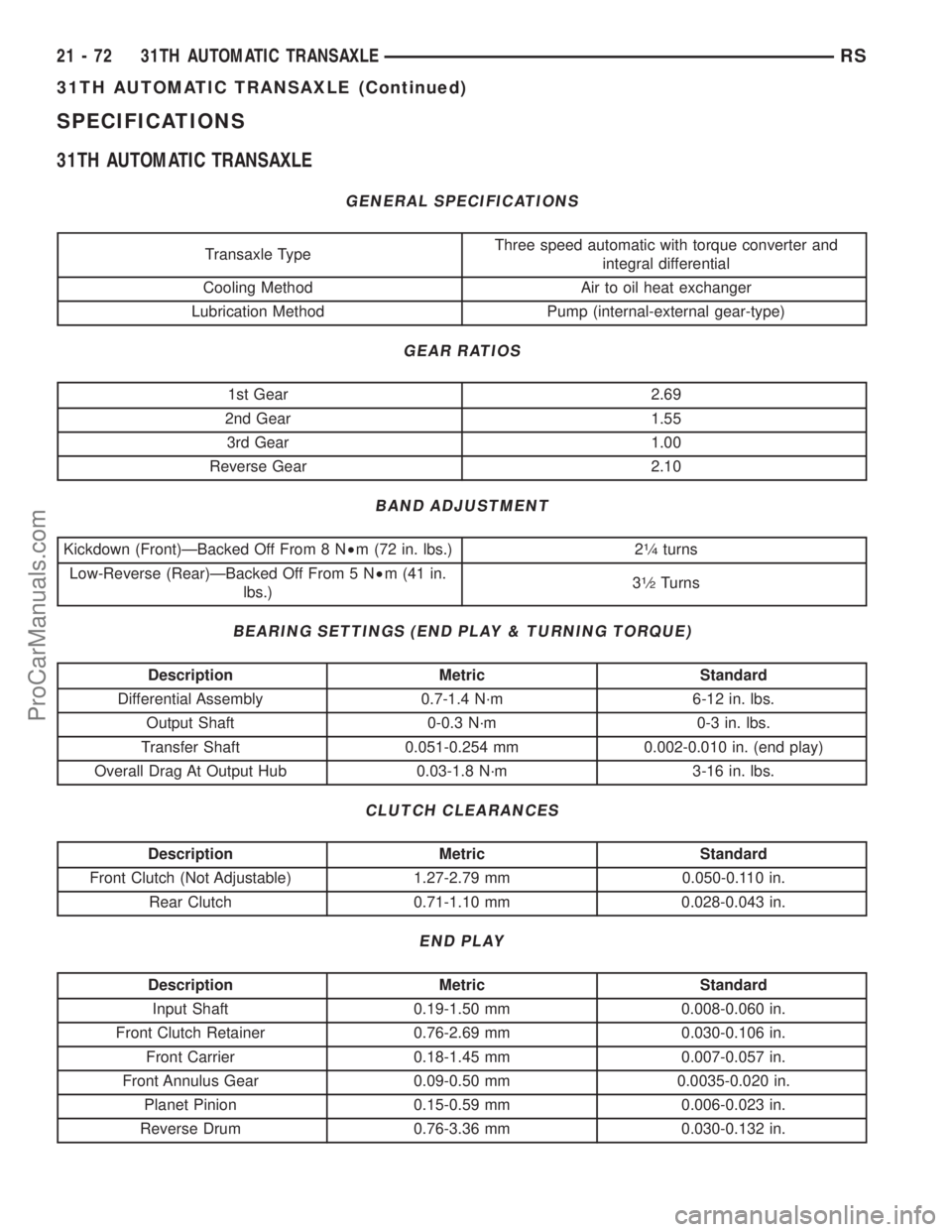
SPECIFICATIONS
31TH AUTOMATIC TRANSAXLE
GENERAL SPECIFICATIONS
Transaxle TypeThree speed automatic with torque converter and
integral differential
Cooling Method Air to oil heat exchanger
Lubrication Method Pump (internal-external gear-type)
GEAR RATIOS
1st Gear 2.69
2nd Gear 1.55
3rd Gear 1.00
Reverse Gear 2.10
BAND ADJUSTMENT
Kickdown (Front)ÐBacked Off From 8 N²m (72 in. lbs.) 21¤4turns
Low-Reverse (Rear)ÐBacked Off From 5 N²m (41 in.
lbs.)3
1¤2Turns
BEARING SETTINGS (END PLAY & TURNING TORQUE)
Description Metric Standard
Differential Assembly 0.7-1.4 N´m 6-12 in. lbs.
Output Shaft 0-0.3 N´m 0-3 in. lbs.
Transfer Shaft 0.051-0.254 mm 0.002-0.010 in. (end play)
Overall Drag At Output Hub 0.03-1.8 N´m 3-16 in. lbs.
CLUTCH CLEARANCES
Description Metric Standard
Front Clutch (Not Adjustable) 1.27-2.79 mm 0.050-0.110 in.
Rear Clutch 0.71-1.10 mm 0.028-0.043 in.
END PLAY
Description Metric Standard
Input Shaft 0.19-1.50 mm 0.008-0.060 in.
Front Clutch Retainer 0.76-2.69 mm 0.030-0.106 in.
Front Carrier 0.18-1.45 mm 0.007-0.057 in.
Front Annulus Gear 0.09-0.50 mm 0.0035-0.020 in.
Planet Pinion 0.15-0.59 mm 0.006-0.023 in.
Reverse Drum 0.76-3.36 mm 0.030-0.132 in.
21 - 72 31TH AUTOMATIC TRANSAXLERS
31TH AUTOMATIC TRANSAXLE (Continued)
ProCarManuals.com
Page 1631 of 2399
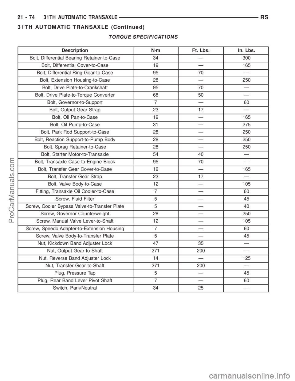
TORQUE SPECIFICATIONS
Description N´m Ft. Lbs. In. Lbs.
Bolt, Differential Bearing Retainer-to-Case 34 Ð 300
Bolt, Differential Cover-to-Case 19 Ð 165
Bolt, Differential Ring Gear-to-Case 95 70 Ð
Bolt, Extension Housing-to-Case 28 Ð 250
Bolt, Drive Plate-to-Crankshaft 95 70 Ð
Bolt, Drive Plate-to-Torque Converter 68 50 Ð
Bolt, Governor-to-Support 7 Ð 60
Bolt, Output Gear Strap 23 17 Ð
Bolt, Oil Pan-to-Case 19 Ð 165
Bolt, Oil Pump-to-Case 31 Ð 275
Bolt, Park Rod Support-to-Case 28 Ð 250
Bolt, Reaction Support-to-Pump Body 28 Ð 250
Bolt, Sprag Retainer-to-Case 28 Ð 250
Bolt, Starter Motor-to-Transaxle 54 40 Ð
Bolt, Transaxle Case-to-Engine Block 95 70 Ð
Bolt, Transfer Gear Cover-to-Case 19 Ð 165
Bolt, Transfer Gear Strap 23 17 Ð
Bolt, Valve Body-to-Case 12 Ð 105
Fitting, Transaxle Oil Cooler-to-Case 7 Ð 60
Screw, Fluid Filter 5 Ð 45
Screw, Cooler Bypass Valve-to-Transfer Plate 5 Ð 40
Screw, Governor Counterweight 28 Ð 250
Screw, Manual Valve Lever-to-Shaft 12 Ð 105
Screw, Speedo Adapter-to-Extension Housing 7 Ð 60
Screw, Valve Body-to-Transfer Plate 5 Ð 45
Nut, Kickdown Band Adjuster Lock 47 35 Ð
Nut, Output Gear-to-Shaft 271 200 Ð
Nut, Reverse Band Adjuster Lock 14 Ð 125
Nut, Transfer Gear-to-Shaft 271 200 Ð
Plug, Pressure Tap 5 Ð 45
Plug, Rear Band Lever Pivot Shaft 7 Ð 60
Switch, Park/Neutral 34 25 Ð
21 - 74 31TH AUTOMATIC TRANSAXLERS
31TH AUTOMATIC TRANSAXLE (Continued)
ProCarManuals.com
Page 1648 of 2399
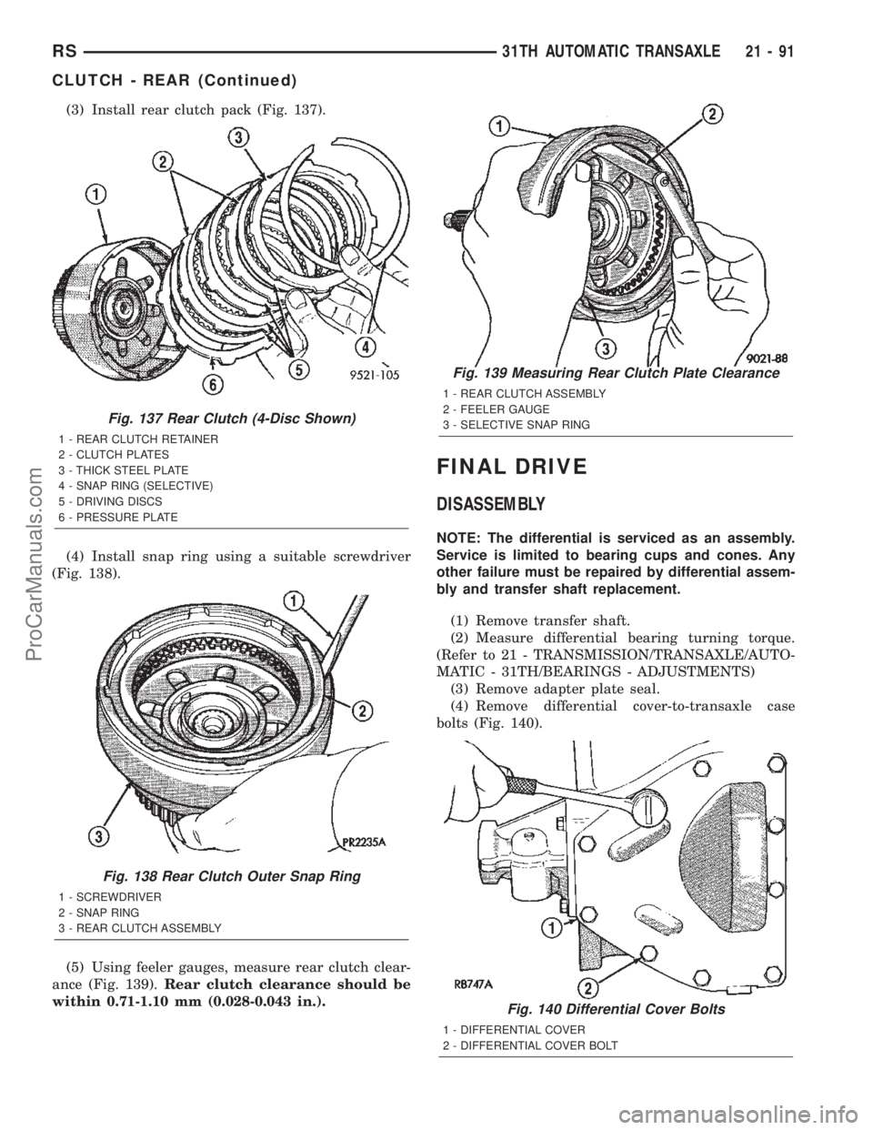
(3) Install rear clutch pack (Fig. 137).
(4) Install snap ring using a suitable screwdriver
(Fig. 138).
(5) Using feeler gauges, measure rear clutch clear-
ance (Fig. 139).Rear clutch clearance should be
within 0.71-1.10 mm (0.028-0.043 in.).
FINAL DRIVE
DISASSEMBLY
NOTE: The differential is serviced as an assembly.
Service is limited to bearing cups and cones. Any
other failure must be repaired by differential assem-
bly and transfer shaft replacement.
(1) Remove transfer shaft.
(2) Measure differential bearing turning torque.
(Refer to 21 - TRANSMISSION/TRANSAXLE/AUTO-
MATIC - 31TH/BEARINGS - ADJUSTMENTS)
(3) Remove adapter plate seal.
(4) Remove differential cover-to-transaxle case
bolts (Fig. 140).
Fig. 137 Rear Clutch (4-Disc Shown)
1 - REAR CLUTCH RETAINER
2 - CLUTCH PLATES
3 - THICK STEEL PLATE
4 - SNAP RING (SELECTIVE)
5 - DRIVING DISCS
6 - PRESSURE PLATE
Fig. 138 Rear Clutch Outer Snap Ring
1 - SCREWDRIVER
2 - SNAP RING
3 - REAR CLUTCH ASSEMBLY
Fig. 139 Measuring Rear Clutch Plate Clearance
1 - REAR CLUTCH ASSEMBLY
2 - FEELER GAUGE
3 - SELECTIVE SNAP RING
Fig. 140 Differential Cover Bolts
1 - DIFFERENTIAL COVER
2 - DIFFERENTIAL COVER BOLT
RS31TH AUTOMATIC TRANSAXLE21-91
CLUTCH - REAR (Continued)
ProCarManuals.com
Page 1727 of 2399
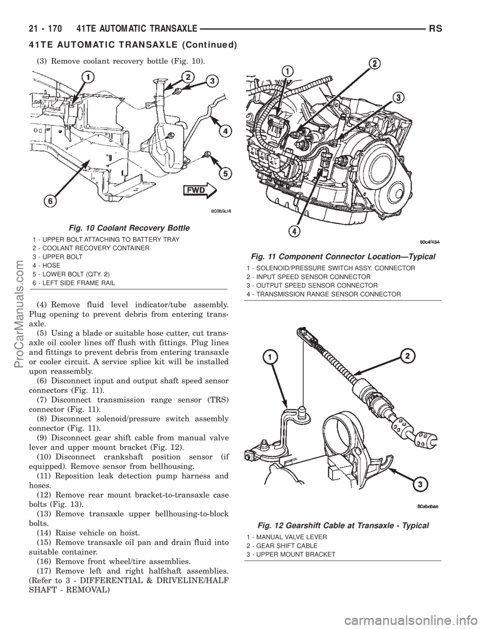
(3) Remove coolant recovery bottle (Fig. 10).
(4) Remove fluid level indicator/tube assembly.
Plug opening to prevent debris from entering trans-
axle.
(5) Using a blade or suitable hose cutter, cut trans-
axle oil cooler lines off flush with fittings. Plug lines
and fittings to prevent debris from entering transaxle
or cooler circuit. A service splice kit will be installed
upon reassembly.
(6) Disconnect input and output shaft speed sensor
connectors (Fig. 11).
(7) Disconnect transmission range sensor (TRS)
connector (Fig. 11).
(8) Disconnect solenoid/pressure switch assembly
connector (Fig. 11).
(9) Disconnect gear shift cable from manual valve
lever and upper mount bracket (Fig. 12).
(10) Disconnect crankshaft position sensor (if
equipped). Remove sensor from bellhousing.
(11) Reposition leak detection pump harness and
hoses.
(12) Remove rear mount bracket-to-transaxle case
bolts (Fig. 13).
(13) Remove transaxle upper bellhousing-to-block
bolts.
(14) Raise vehicle on hoist.
(15) Remove transaxle oil pan and drain fluid into
suitable container.
(16) Remove front wheel/tire assemblies.
(17) Remove left and right halfshaft assemblies.
(Refer to 3 - DIFFERENTIAL & DRIVELINE/HALF
SHAFT - REMOVAL)
Fig. 10 Coolant Recovery Bottle
1 - UPPER BOLT ATTACHING TO BATTERY TRAY
2 - COOLANT RECOVERY CONTAINER
3 - UPPER BOLT
4 - HOSE
5 - LOWER BOLT (QTY. 2)
6 - LEFT SIDE FRAME RAIL
Fig. 11 Component Connector LocationÐTypical
1 - SOLENOID/PRESSURE SWITCH ASSY. CONNECTOR
2 - INPUT SPEED SENSOR CONNECTOR
3 - OUTPUT SPEED SENSOR CONNECTOR
4 - TRANSMISSION RANGE SENSOR CONNECTOR
Fig. 12 Gearshift Cable at Transaxle - Typical
1 - MANUAL VALVE LEVER
2 - GEAR SHIFT CABLE
3 - UPPER MOUNT BRACKET
21 - 170 41TE AUTOMATIC TRANSAXLERS
41TE AUTOMATIC TRANSAXLE (Continued)
ProCarManuals.com
Page 1728 of 2399
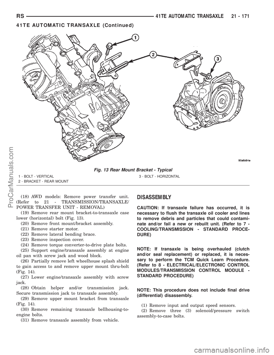
(18) AWD models: Remove power transfer unit.
(Refer to 21 - TRANSMISSION/TRANSAXLE/
POWER TRANSFER UNIT - REMOVAL)
(19) Remove rear mount bracket-to-transaxle case
lower (horizontal) bolt (Fig. 13).
(20) Remove front mount/bracket assembly.
(21) Remove starter motor.
(22) Remove lateral bending brace.
(23) Remove inspection cover.
(24) Remove torque converter-to-drive plate bolts.
(25) Support engine/transaxle assembly at engine
oil pan with screw jack and wood block.
(26) Partially remove left wheelhouse splash shield
to gain access to and remove upper mount thru-bolt
(Fig. 14).
(27) Lower engine/transaxle assembly with screw
jack.
(28) Obtain helper and/or transmission jack.
Secure transmission jack to transaxle assembly.
(29) Remove upper mount bracket from transaxle
(Fig. 14).
(30) Remove remaining transaxle bellhousing-to-
engine bolts.
(31) Remove transaxle assembly from vehicle.DISASSEMBLY
CAUTION: If transaxle failure has occurred, it is
necessary to flush the transaxle oil cooler and lines
to remove debris and particles that could contami-
nate and/or fail a new or rebuilt unit. (Refer to 7 -
COOLING/TRANSMISSION - STANDARD PROCE-
DURE)
NOTE: If transaxle is being overhauled (clutch
and/or seal replacement) or replaced, it is neces-
sary to perform the TCM Quick Learn Procedure.
(Refer to 8 - ELECTRICAL/ELECTRONIC CONTROL
MODULES/TRANSMISSION CONTROL MODULE -
STANDARD PROCEDURE)
NOTE: This procedure does not include final drive
(differential) disassembly.
(1) Remove input and output speed sensors.
(2) Remove three (3) solenoid/pressure switch
assembly-to-case bolts.
Fig. 13 Rear Mount Bracket - Typical
1 - BOLT - VERTICAL
2 - BRACKET - REAR MOUNT3 - BOLT - HORIZONTAL
RS41TE AUTOMATIC TRANSAXLE21 - 171
41TE AUTOMATIC TRANSAXLE (Continued)
ProCarManuals.com
Page 1771 of 2399
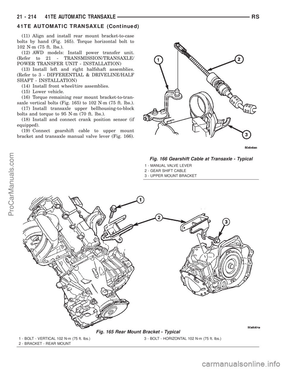
(11) Align and install rear mount bracket-to-case
bolts by hand (Fig. 165). Torque horizontal bolt to
102 N´m (75 ft. lbs.).
(12) AWD models: Install power transfer unit.
(Refer to 21 - TRANSMISSION/TRANSAXLE/
POWER TRANSFER UNIT - INSTALLATION)
(13) Install left and right halfshaft assemblies.
(Refer to 3 - DIFFERENTIAL & DRIVELINE/HALF
SHAFT - INSTALLATION)
(14) Install front wheel/tire assemblies.
(15) Lower vehicle.
(16) Torque remaining rear mount bracket-to-tran-
saxle vertical bolts (Fig. 165) to 102 N´m (75 ft. lbs.).
(17) Install transaxle upper bellhousing-to-block
bolts and torque to 95 N´m (70 ft. lbs.).
(18) Install and connect crank position sensor (if
equipped).
(19) Connect gearshift cable to upper mount
bracket and transaxle manual valve lever (Fig. 166).
Fig. 165 Rear Mount Bracket - Typical
1 - BOLT - VERTICAL 102 N´m (75 ft. lbs.)
2 - BRACKET - REAR MOUNT3 - BOLT - HORIZONTAL 102 N´m (75 ft. lbs.)
Fig. 166 Gearshift Cable at Transaxle - Typical
1 - MANUAL VALVE LEVER
2 - GEAR SHIFT CABLE
3 - UPPER MOUNT BRACKET
21 - 214 41TE AUTOMATIC TRANSAXLERS
41TE AUTOMATIC TRANSAXLE (Continued)
ProCarManuals.com
Page 1795 of 2399
OPERATION
The three input clutches are responsible for driving
different components of the planetary geartrain.
NOTE: Refer to the ªElements In Useº chart in Diag-
nosis and Testing for a collective view of which
clutch elements are applied at each position of the
selector lever.
UNDERDRIVE CLUTCH
The underdrive clutch is hydraulically applied in
first, second, and third (direct) gears by pressurized
fluid against the underdrive piston. When the under-
drive clutch is applied, the underdrive hub drives the
rear sun gear.
OVERDRIVE CLUTCH
The overdrive clutch is hydraulically applied in
third (direct) and overdrive gears by pressurized fluid
against the overdrive/reverse piston. When the over-
drive clutch is applied, the overdrive hub drives the
front planet carrier.
REVERSE CLUTCH
The reverse clutch is hydraulically applied in
reverse gear only by pressurized fluid against the
overdrive/reverse piston. When the reverse clutch is
applied, the front sun gear assembly is driven.
FINAL DRIVE
DISASSEMBLY
NOTE: The differential is serviced as an assembly.
Differential service is limited to bearing cups and
cones. Any other differential component failure
must be remedied by differential assembly and
transfer shaft replacement.
The transfer shaft should be removed for differen-
tial repair and bearing turning torque checking.
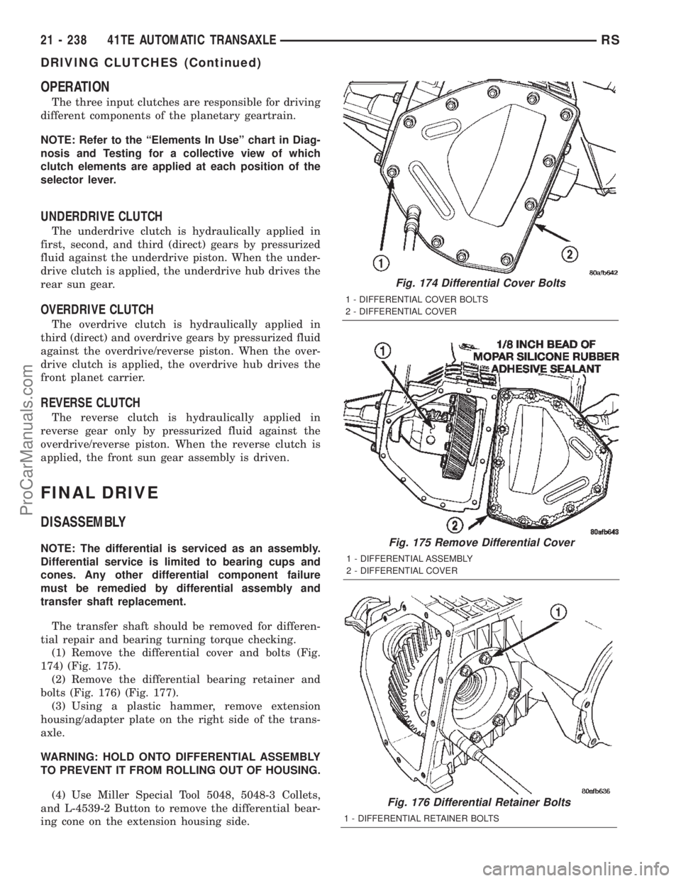
(1) Remove the differential cover and bolts (Fig.
174) (Fig. 175).
(2) Remove the differential bearing retainer and
bolts (Fig. 176) (Fig. 177).
(3) Using a plastic hammer, remove extension
housing/adapter plate on the right side of the trans-
axle.
WARNING: HOLD ONTO DIFFERENTIAL ASSEMBLY
TO PREVENT IT FROM ROLLING OUT OF HOUSING.
(4) Use Miller Special Tool 5048, 5048-3 Collets,
and L-4539-2 Button to remove the differential bear-
ing cone on the extension housing side.
Fig. 174 Differential Cover Bolts
1 - DIFFERENTIAL COVER BOLTS
2 - DIFFERENTIAL COVER
Fig. 175 Remove Differential Cover
1 - DIFFERENTIAL ASSEMBLY
2 - DIFFERENTIAL COVER
Fig. 176 Differential Retainer Bolts
1 - DIFFERENTIAL RETAINER BOLTS
21 - 238 41TE AUTOMATIC TRANSAXLERS
DRIVING CLUTCHES (Continued)
ProCarManuals.com
Page 1866 of 2399
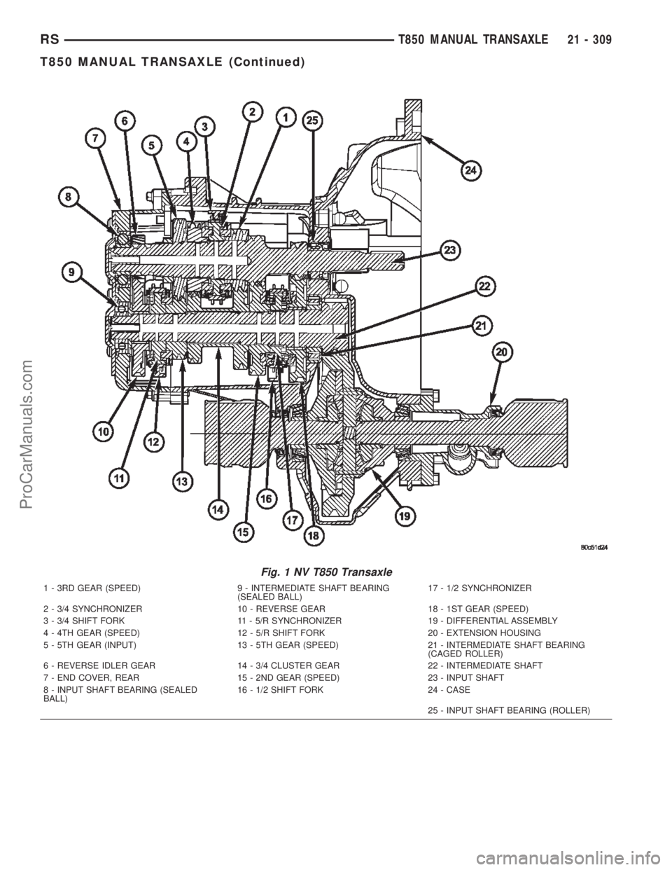
Fig. 1 NV T850 Transaxle
1 - 3RD GEAR (SPEED) 9 - INTERMEDIATE SHAFT BEARING
(SEALED BALL)17 - 1/2 SYNCHRONIZER
2 - 3/4 SYNCHRONIZER 10 - REVERSE GEAR 18 - 1ST GEAR (SPEED)
3 - 3/4 SHIFT FORK 11 - 5/R SYNCHRONIZER 19 - DIFFERENTIAL ASSEMBLY
4 - 4TH GEAR (SPEED) 12 - 5/R SHIFT FORK 20 - EXTENSION HOUSING
5 - 5TH GEAR (INPUT) 13 - 5TH GEAR (SPEED) 21 - INTERMEDIATE SHAFT BEARING
(CAGED ROLLER)
6 - REVERSE IDLER GEAR 14 - 3/4 CLUSTER GEAR 22 - INTERMEDIATE SHAFT
7 - END COVER, REAR 15 - 2ND GEAR (SPEED) 23 - INPUT SHAFT
8 - INPUT SHAFT BEARING (SEALED
BALL)16 - 1/2 SHIFT FORK 24 - CASE
25 - INPUT SHAFT BEARING (ROLLER)
RST850 MANUAL TRANSAXLE21 - 309
T850 MANUAL TRANSAXLE (Continued)
ProCarManuals.com
Page 1944 of 2399
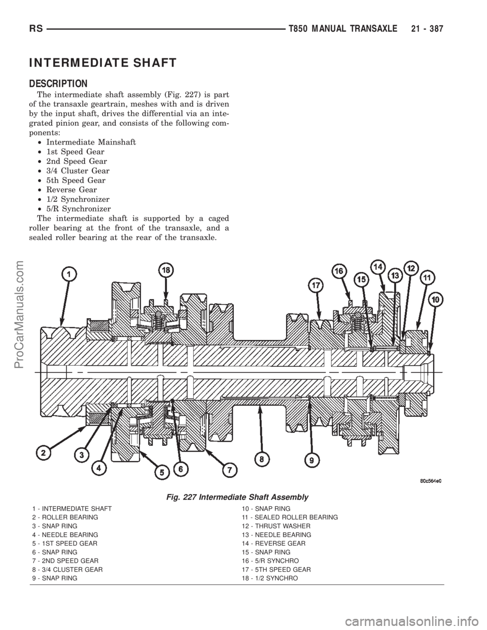
INTERMEDIATE SHAFT
DESCRIPTION
The intermediate shaft assembly (Fig. 227) is part
of the transaxle geartrain, meshes with and is driven
by the input shaft, drives the differential via an inte-
grated pinion gear, and consists of the following com-
ponents:
²Intermediate Mainshaft
²1st Speed Gear
²2nd Speed Gear
²3/4 Cluster Gear
²5th Speed Gear
²Reverse Gear
²1/2 Synchronizer
²5/R Synchronizer
The intermediate shaft is supported by a caged
roller bearing at the front of the transaxle, and a
sealed roller bearing at the rear of the transaxle.
Fig. 227 Intermediate Shaft Assembly
1 - INTERMEDIATE SHAFT 10 - SNAP RING
2 - ROLLER BEARING 11 - SEALED ROLLER BEARING
3 - SNAP RING 12 - THRUST WASHER
4 - NEEDLE BEARING 13 - NEEDLE BEARING
5 - 1ST SPEED GEAR 14 - REVERSE GEAR
6 - SNAP RING 15 - SNAP RING
7 - 2ND SPEED GEAR 16 - 5/R SYNCHRO
8 - 3/4 CLUSTER GEAR 17 - 5TH SPEED GEAR
9 - SNAP RING 18 - 1/2 SYNCHRO
RST850 MANUAL TRANSAXLE21 - 387
ProCarManuals.com