head gasket CHRYSLER TOWN AND COUNTRY 2002 Workshop Manual
[x] Cancel search | Manufacturer: CHRYSLER, Model Year: 2002, Model line: TOWN AND COUNTRY, Model: CHRYSLER TOWN AND COUNTRY 2002Pages: 2399, PDF Size: 57.96 MB
Page 1389 of 2399

(2) Remove front wiper unit (Refer to 8 - ELEC-
TRICAL/WIPERS/WASHERS/WIPER MODULE -
REMOVAL).
(3) Remove air cleaner housing assembly.
(4) Support engine and remove right engine mount
(Refer to 9 - ENGINE/ENGINE MOUNTING/RIGHT
MOUNT - REMOVAL).
(5) Remove outer timing belt cover (Refer to 9 -
ENGINE/VALVE TIMING/TIMING BELT / CHAIN
COVER(S) - REMOVAL).
(6) Remove timing belt (Refer to 9 - ENGINE/
VALVE TIMING/TIMING BELT/CHAIN AND
SPROCKETS - REMOVAL).
(7) Remove inner timing belt cover (Refer to 9 -
ENGINE/VALVE TIMING/TIMING BELT / CHAIN
COVER(S) - REMOVAL).
(8) Remove cylinder head cover/intake manifold
(Refer to 9 - ENGINE/CYLINDER HEAD/CYLIN-
DER HEAD COVER(S) - REMOVAL).(9) Remove rocker arm from lifter (Fig. 30).
INSTALLATION
(1) Clean and inspect gasket sealing surfaces.
(2) Install new gasket on cylinder head.
(3) Lubricate lifter ball end of lifter(s), valve(s),
and rocker arm roller(s) with MopartEngine Oil
Supplement or equivlalent.
(4) Connect rocker arm(s) to lifter and reposition
on valve(s) (Fig. 30).
(5) Install cylinder head cover/intake manifold
(Refer to 9 - ENGINE/CYLINDER HEAD/CYLIN-
DER HEAD COVER(S) - INSTALLATION).
(6) Install inner timing belt cover (Refer to 9 -
ENGINE/VALVE TIMING/TIMING BELT / CHAIN
COVER(S) - INSTALLATION).
(7) Install timing belt (Refer to 9 - ENGINE/
VALVE TIMING/TIMING BELT/CHAIN AND
SPROCKETS - INSTALLATION) .
(8) Install outer timing belt cover (Refer to 9 -
ENGINE/VALVE TIMING/TIMING BELT / CHAIN
COVER(S) - INSTALLATION).
(9) Install right engine mount (Refer to 9 -
ENGINE/ENGINE MOUNTING/RIGHT MOUNT -
INSTALLATION).
(10) Install air cleaner housing assembly.
Fig. 29 CYLINDER HEAD ASSEMBLY
1 - VALVE SPRING
2 - CYLINDER HEAD BOLT
3 - GLOW PLUG
4 - COOLANT TEMPERATURE SENSOR
5 - CYLINDER HEAD ALIGNMENT DOWEL
6 - CYLINDER BLOCK
7 - CYLINDER LINER
8 - ENGINE BLOCK DECK
9 - CYLINDER HEAD GASKET
10 - CYLINDER HEAD
11 - ROCKER ARM AND LIFTER ASSEMBLY
Fig. 30 ROCKER ARM ASSEMBLY
1 - ROCKER ARM ASSEMBLY
2 - CYLINDER HEAD COVER/INTAKE MANIFOLD
3 - HYDRAULIC LIFTER
4 - CYLINDER HEAD
5 - VALVE
9a - 28 ENGINERG
ROCKER ARMS (Continued)
ProCarManuals.com
Page 1390 of 2399

(11) Install front wiper unit (Refer to 8 - ELEC-
TRICAL/WIPERS/WASHERS/WIPER MODULE -
INSTALLATION).
(12) Connect negative battery cable.
HYDRAULIC LIFTERS
DESCRIPTION
Valve lash is controlled by hydraulic tappets
located inside the cylinder head, in tappet bores
below the camshafts (Fig. 31).
REMOVAL
(1) Disconnect negative battery cable.
(2) Remove front wiper unit (Refer to 8 - ELEC-
TRICAL/WIPERS/WASHERS/WIPER MODULE -
REMOVAL).(3) Remove engine cover (Refer to 9 - ENGINE -
REMOVAL).
(4) Support engine and remove right engine mount
(Refer to 9 - ENGINE/ENGINE MOUNTING/RIGHT
MOUNT - REMOVAL).
(5) Remove outer timing belt cover (Refer to 9 -
ENGINE/VALVE TIMING/TIMING BELT / CHAIN
COVER(S) - REMOVAL).
CAUTION: Before removing the cylinder head cover/
intake manifold or the timing belt the engine must
put at 90É after TDC. Failure to do so could result in
valve and/or piston damage during reassembly.
(Refer to 9 - ENGINE/VALVE TIMING - STANDARD
PROCEDURE)
(6) Remove timing belt (Refer to 9 - ENGINE/
VALVE TIMING/TIMING BELT/CHAIN AND
SPROCKETS - REMOVAL).
(7) Remove inner timing belt cover (Refer to 9 -
ENGINE/VALVE TIMING/TIMING BELT / CHAIN
COVER(S) - REMOVAL).
(8) Remove cylinder head cover/intake manifold
(Fig. 32)(Refer to 9 - ENGINE/CYLINDER HEAD/
CYLINDER HEAD COVER(S) - REMOVAL).
Fig. 31 CYLINDER HEAD ASSEMBLY
1 - VALVE SPRING
2 - CYLINDER HEAD BOLT
3 - GLOW PLUG
4 - COOLANT TEMPERATURE SENSOR
5 - CYLINDER HEAD ALIGNMENT DOWEL
6 - CYLINDER BLOCK
7 - CYLINDER LINER
8 - ENGINE BLOCK DECK
9 - CYLINDER HEAD GASKET
10 - CYLINDER HEAD
11 - ROCKER ARM AND LIFTER ASSEMBLY
Fig. 32 CYLINDER HEAD COVER/INTAKE
MANIFOLD
1 - CYLINDER HEAD COVER/INTAKE MANIFOLD BOLTS(LONG)
2 - CYLINDER HEAD COVER/INTAKE MANIFOLD
3 - CYLINDER HEAD
4 - CYLINDER HEAD COVER/INTAKE MANIFOLD GASKET
5 - CYLINDER HEAD COVER/INTAKE MANIFOLD
BOLTS(SHORT)
RGENGINE9a-29
ROCKER ARMS (Continued)
ProCarManuals.com
Page 1418 of 2399
(3) Install accessory drive belt (Refer to 7 - COOL-
ING/ACCESSORY DRIVE/DRIVE BELTS - INSTAL-
LATION).
(4) Install power steering belt (Refer to 7 - COOL-
ING/ACCESSORY DRIVE/DRIVE BELTS - INSTAL-
LATION).
(5) Install right engine mount.
(6) Install air cleaner housing.
(7) Install engine cover (Refer to 9 - ENGINE -
INSTALLATION).
(8) Connect negative battery cable.
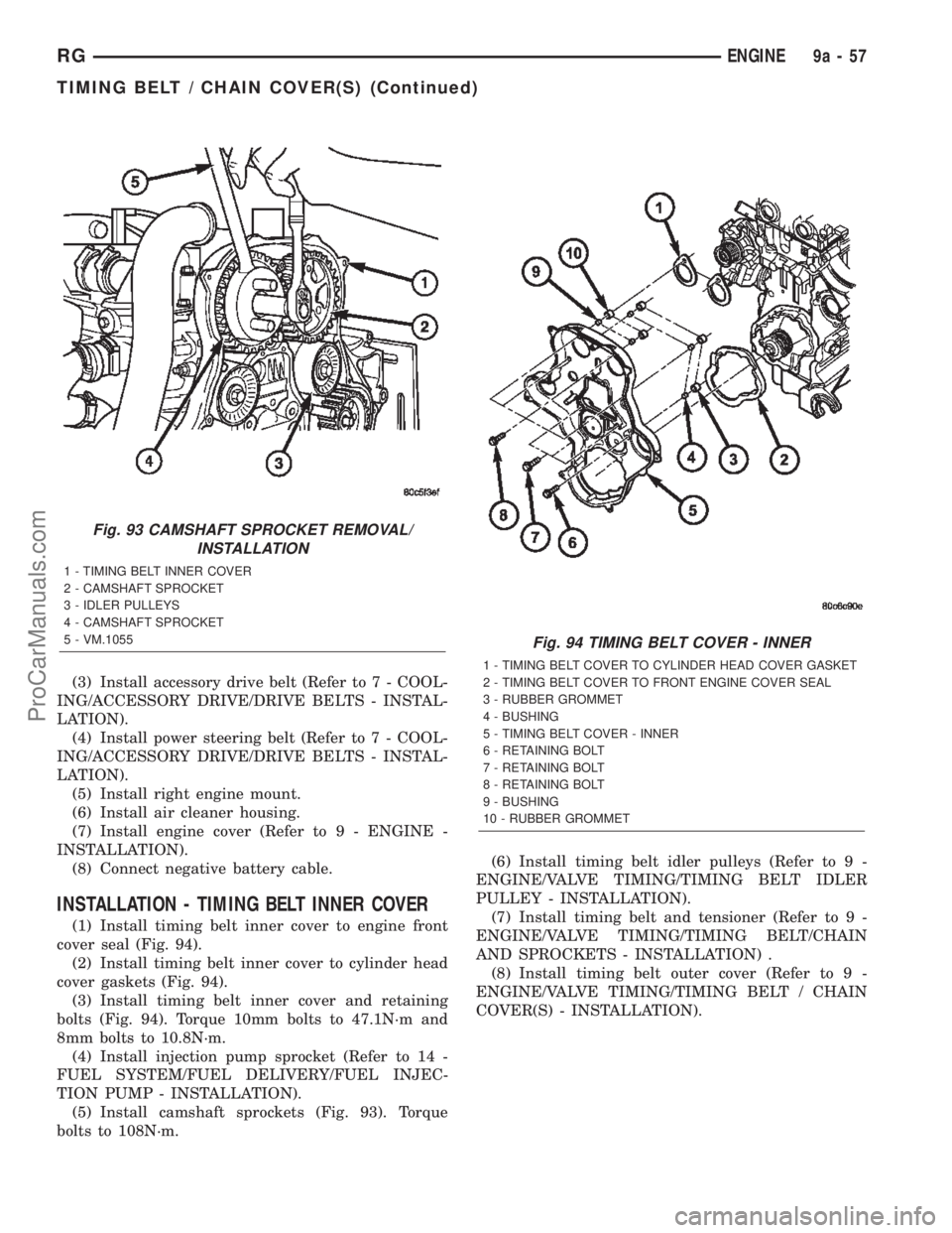
INSTALLATION - TIMING BELT INNER COVER
(1) Install timing belt inner cover to engine front
cover seal (Fig. 94).
(2) Install timing belt inner cover to cylinder head
cover gaskets (Fig. 94).
(3) Install timing belt inner cover and retaining
bolts (Fig. 94). Torque 10mm bolts to 47.1N´m and
8mm bolts to 10.8N´m.
(4) Install injection pump sprocket (Refer to 14 -
FUEL SYSTEM/FUEL DELIVERY/FUEL INJEC-
TION PUMP - INSTALLATION).
(5) Install camshaft sprockets (Fig. 93). Torque
bolts to 108N´m.(6) Install timing belt idler pulleys (Refer to 9 -
ENGINE/VALVE TIMING/TIMING BELT IDLER
PULLEY - INSTALLATION).
(7) Install timing belt and tensioner (Refer to 9 -
ENGINE/VALVE TIMING/TIMING BELT/CHAIN
AND SPROCKETS - INSTALLATION) .
(8) Install timing belt outer cover (Refer to 9 -
ENGINE/VALVE TIMING/TIMING BELT / CHAIN
COVER(S) - INSTALLATION).
Fig. 93 CAMSHAFT SPROCKET REMOVAL/
INSTALLATION
1 - TIMING BELT INNER COVER
2 - CAMSHAFT SPROCKET
3 - IDLER PULLEYS
4 - CAMSHAFT SPROCKET
5 - VM.1055
Fig. 94 TIMING BELT COVER - INNER
1 - TIMING BELT COVER TO CYLINDER HEAD COVER GASKET
2 - TIMING BELT COVER TO FRONT ENGINE COVER SEAL
3 - RUBBER GROMMET
4 - BUSHING
5 - TIMING BELT COVER - INNER
6 - RETAINING BOLT
7 - RETAINING BOLT
8 - RETAINING BOLT
9 - BUSHING
10 - RUBBER GROMMET
RGENGINE9a-57
TIMING BELT / CHAIN COVER(S) (Continued)
ProCarManuals.com
Page 1425 of 2399
OPERATION
The exhaust system contains, quiets, and cleans
the exhaust gases generated by the engine.
DIAGNOSIS AND TESTING
DIAGNOSIS AND TESTING - EXCESSIVE
EXHAUST SYSTEM NOISE
CONDITION POSSIBLE CAUSES CORRECTION
EXCESSIVE EXHAUST NOISE
(UNDER HOOD)1. Exhaust manifold cracked or
broken.1. Replace manifold.
2. Manifold to cylinder head leak. 2. Tighten manifold and/or replace
gasket.
3. EGR Valve to manifold gasket
leakage.3. Tighten fasteners or replace
gasket.
4. EGR Valve to EGR tube gasket
leakage.4. Tighten fasteners or replace
gasket.
5. EGR tube to manifold tube
leakage.5. Tighten tube nut.
6. Exhaust flex-joint to manifold
leak.6. Tighten joint fasteners and/or
replace gasket.
7. Exhaust flex-joint. 7. Replace catalytic converter
assembly.
8. Pipe and shell noise from front
exhaust pipe.8. Characteristic of single wall pipe.
EXCESSIVE EXHAUST NOISE 1. Leak at exhaust pipe joints. 1. Tighten clamps at leaking joints.
2. Burned or rusted out muffler
assembly or exhaust pipe.2. Replace muffler resonator tailpipe
assembly or exhaust pipe with
catalytic converter assembly.
3. Burned or rusted out resonator. 3. Replace muffler resonator tailpipe
assembly.
4. Restriction in exhaust system. 4. Perform Exhaust System
Restriction Check. Replace
component as necessary.
5. Converter material in muffler. 5. Replace muffler and converter
assemblies. Check fuel injection and
ignition systems for proper
operation.
DIAGNOSIS AND TESTING - EXHAUST SYSTEM
RESTRICTION CHECK
Exhaust system restriction can be checked by mea-
suring back pressure using the DRB IIItand PEP
module pressure tester.WARNING: THE NORMAL OPERATING TEMPERA-
TURE OF THE EXHAUST SYSTEM IS VERY HIGH.
THEREFORE, NEVER WORK AROUND OR ATTEMPT
TO SERVICE ANY PART OF THE EXHAUST SYSTEM
UNTIL IT IS COOLED. SPECIAL CARE SHOULD BE
TAKEN WHEN WORKING NEAR THE CATALYTIC
CONVERTER. THE TEMPERATURE OF THE CON-
VERTER RISES TO A HIGH LEVEL AFTER A SHORT
PERIOD OF ENGINE OPERATION TIME.
11 - 2 EXHAUST SYSTEMRS
EXHAUST SYSTEM (Continued)
ProCarManuals.com
Page 1511 of 2399
CONDITION POSSIBLE CAUSES CORRECTION
9. Loose inner tie rod. 9. Replace power steering gear.
10. Defective steering gear rotary
valve.10. Replace power steering gear.
NOTE: * Steering shudder can be expected in new
vehicles and vehicles with recent steering system
repairs. Shudder should dissipate after the vehicle
has been driven several weeks.
NOTE: ** To evaluate this condition, it may be nec-
essary to disconnect the coupling at the base of the
steering column. Turn the steering wheel and feel or
listen for internal rubbing in steering column. To
avoid damaging the column clockspring, note the
following. Before disconnecting coupling, place
tires in the straight-ahead position and center steer-
ing wheel. Once disconnected, DO NOT rotate
steering wheel more than one revolution in eitherdirection and place steering wheel in original loca-
tion before reconnecting coupling. If this position is
lost, the steering column clockspring must be
recentered following the procedure found within the
procedure for steering column installation in the
steering column section.
NOTE: *** Increased low speed or stationary steer-
ing effort can be expected if the steering fluid is at
a high temperature. High fluid temperature usually
results from high engine rpm due to trailer towing,
ascending grades, or racing the engine for pro-
longed periods of time.
POWER STEERING FLUID
CONDITION POSSIBLE CAUSES CORRECTION
LOW FLUID LEVEL WITH
VISIBLE LEAK.1. Loose power steering hose
fittings.1. Tighten the fitting to its specified torque.
2. Damaged or missing fitting seal,
gasket, or O-ring.2. Replace as necessary.
3. Power steering component
leaking.3. Repair or replace the leaking component
as required.
AERATED FLUID.* 1. Low fluid level. 1. Fill power steering fluid reservoir to
proper level.
2. Air leak at supply hose, power
steering fluid reservoir or pump.2. Inspect for proper sealing. Repair as
necessary.
3. Cracked power steering pump
housing.3. Replace the power steering pump.
RESERVOIR FLUID
OVERFLOW AND FLUID
THAT IS MILKY IN COLOR1. Water contamination of power
steering fluid.1. Drain the power steering fluid from the
system. Flush the system with fresh clean
power steering fluid, drain, then refill to the
proper level.
NOTE: * Extremely cold temperatures may cause
power steering fluid aeration. Aeration should sub-
side as fluid warms.
19 - 8 STEERINGRS
STEERING (Continued)
ProCarManuals.com
Page 1729 of 2399
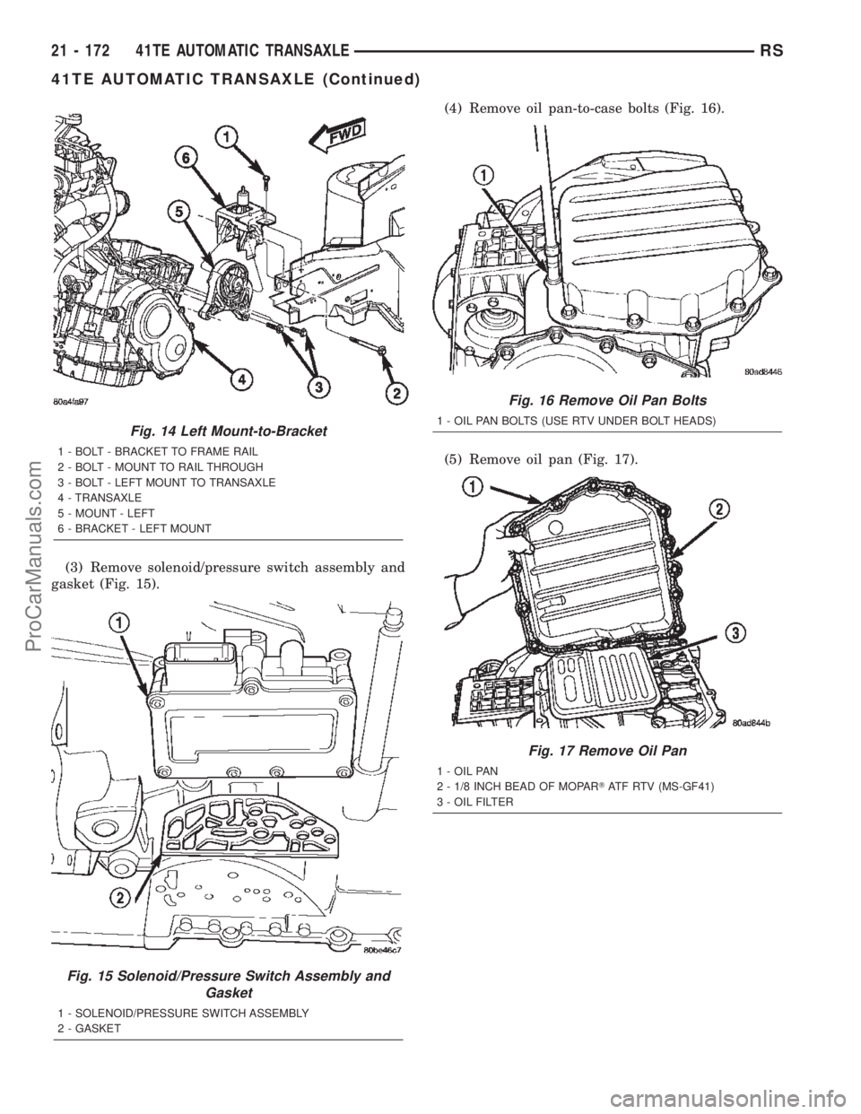
(3) Remove solenoid/pressure switch assembly and
gasket (Fig. 15).(4) Remove oil pan-to-case bolts (Fig. 16).
(5) Remove oil pan (Fig. 17).
Fig. 14 Left Mount-to-Bracket
1 - BOLT - BRACKET TO FRAME RAIL
2 - BOLT - MOUNT TO RAIL THROUGH
3 - BOLT - LEFT MOUNT TO TRANSAXLE
4 - TRANSAXLE
5 - MOUNT - LEFT
6 - BRACKET - LEFT MOUNT
Fig. 15 Solenoid/Pressure Switch Assembly and
Gasket
1 - SOLENOID/PRESSURE SWITCH ASSEMBLY
2 - GASKET
Fig. 16 Remove Oil Pan Bolts
1 - OIL PAN BOLTS (USE RTV UNDER BOLT HEADS)
Fig. 17 Remove Oil Pan
1 - OIL PAN
2 - 1/8 INCH BEAD OF MOPARTATF RTV (MS-GF41)
3 - OIL FILTER
21 - 172 41TE AUTOMATIC TRANSAXLERS
41TE AUTOMATIC TRANSAXLE (Continued)
ProCarManuals.com
Page 2304 of 2399
CAUTION - A/C PLUMBING
CAUTION:: Liquid refrigerant is corrosive to metal
surfaces. Follow the operating instructions supplied
with the service equipment being used.
CAUTION: Never add R-12 to a refrigerant system
designed to use R-134a. Damage to the system will
result.
CAUTION: R-12 refrigerant oil must not be mixed
with R-134a refrigerant oil. They are not compatible.
CAUTION: Do not use R-12 equipment or parts on
the R-134a system. Damage to the system will
result. All parts, tools, and equipment must be
designed for R-134a refrigerant.
CAUTION: Do not discharge refrigerant into the
atmosphere. Use an R-134a refrigerant recovery/re-
cycling device that meets SAE Standard J2210.
CAUTION: The refrigerant must be recovered com-
pletely from the system before opening any fitting
or connection. Open the fittings with caution, even
after the system has been discharged. If any pres-
sure is noticed as a fitting is loosened, tighten the
fitting and recover the refrigerant from the system
again.
CAUTION: The refrigerant system must always be
evacuated before charging.
CAUTION: Do not overcharge the refrigerant sys-
tem. This will cause excessive compressor head
pressure and can cause noise and system failure.
CAUTION: Do not open the refrigerant system or
remove the sealing caps from a replacement com-
ponent until it is to be installed. This will prevent
contamination in the system.
CAUTION: Before disconnecting a component,
clean the outside of the fittings thoroughly to pre-
vent contamination from entering the refrigerant
system.
CAUTION: When it is necessary to open the refrig-
erant system, have everything needed to service
the system ready. Immediately after disconnecting acomponent from the refrigerant system, seal the
open fittings with a cap or plug to prevent the
entrance of dirt and moisture. The refrigerant sys-
tem should not be left open to the atmosphere any
longer than necessary.
CAUTION: Before connecting an open refrigerant
fitting, always install a new seal or gasket. All fit-
tings with O-rings need to be coated with refriger-
ant oil before installation. Use only O-rings that are
the correct size and approved for use with R-134a
refrigerant. Failure to do so may result in a leak.
Coat the fitting and seal with clean refrigerant oil
before connecting. Unified plumbing connections
with gaskets cannot be serviced with O-rings. The
gaskets are not reusable and new gaskets do not
require lubrication before installing.
CAUTION: When installing a refrigerant line, avoid
sharp bends that may restrict refrigerant flow. A
good rule for the flexible hose refrigerant lines is to
keep the radius of all bends at least ten times the
diameter of the hose. Sharp bends will reduce the
flow of refrigerant.
CAUTION: Position the refrigerant lines away from
exhaust system components or any sharp edges,
which may damage the line. The flexible hose lines
should be routed so they are at least 80 millimeters
(3 inches) from the exhaust manifold. Inspect all
flexible refrigerant system hose lines at least once
a year to make sure they are in good condition and
properly routed.
CAUTION: High pressures are produced in the
refrigerant system when it is operating. Extreme
care must be exercised to make sure that all refrig-
erant system connections are pressure tight.
CAUTION: Tighten refrigerant fittings only to the
specified torque. The aluminum fittings used in the
refrigerant system will not tolerate overtightening.
CAUTION: When disconnecting a refrigerant fitting,
use a wrench on both halves of the fitting. This will
prevent twisting of the refrigerant lines or tubes.
CAUTION: Refrigerant oil will absorb moisture from
the atmosphere if left uncapped. Do not open a
container of refrigerant oil until you are ready to
use it. Replace the cap on the oil container immedi-
ately after using. Store refrigerant oil only in a
clean, airtight, and moisture-free container.
RSPLUMBING - FRONT24-61
PLUMBING - FRONT (Continued)
ProCarManuals.com
Page 2380 of 2399
(2) Disconnect the fresh air makeup hose on rear
valve cover.
(3) Remove the air box bolt.
(4) Remove the hose clamp at throttle body.
(5) Unlatch 2 clamps for air box cover.
(6) Remove air box cover.
(7) Disconnect the washer fluid fill hose.
(8) Remove air box.
(9) Remove the 2 bolts at the EGR valve.
(10) Remove the 2 bolts at the intake manifold.
(11) Remove front EGR tube.
REMOVAL - REAR TUBE - 3.5L
(1) Remove the battery, refer to the Battery sec-
tion.
(2) Remove the Battery tray/vacuum reservoir.
(3) Remove the speed control servo and bracket
and relocate.
(4) Remove the 2 bolts from the EGR valve.
(5) Remove the 2 bolts from the rear cylinder
head.
(6) Remove the EGR rear tube.
INSTALLATION
INSTALLATION - 2.4L
(1) Loose install EGR tube and gasket with attach-
ing bolts at intake manifold.
(2) Loose install EGR tube and gasket with attach-
ing bolts at EGR valve.
(3) Tighten bolts to EGR valve to 11.9 N´m (105
20 ins. lbs.).
(4) Tighten bolts to Intake manifold to 11.9 N´m
(105 20 ins. lbs.).
INSTALLATION - FRONT TUBE - 3.5L
(1) Install front EGR tube and gaskets.
(2) Install the 2 bolts at the EGR valve.
(3) Install the 2 bolts at the intake manifold.
(4) Tighten all 4 bolts.
(5) Install air box.
(6) Connect the washer fluid fill hose.
(7) Install air box cover.
(8) Latch 2 clamps for air box cover.
(9) Install the hose clamp at throttle body.
(10) Install the air box bolt.
(11) Connect the fresh air makeup hose on rear
valve cover.
(12) Connect the negative battery cable.
INSTALLATION - REAR TUBE - 3.5L
(1) Install the EGR rear tube.
(2) Install the 2 bolts to the rear cylinder head.
(3) Install the 2 bolts to the EGR valve.
(4) Tighten the 4 bolts.(5) Install the speed control servo and bracket,
refer to the speed control section.
(6) Install the Battery tray/vacuum reservoir refer
to the battery section.
(7) Install the battery, refer to the Battery section.
VA LV E
DESCRIPTION
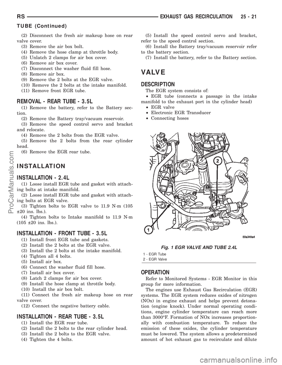
The EGR system consists of:
²EGR tube (connects a passage in the intake
manifold to the exhaust port in the cylinder head)
²EGR valve
²Electronic EGR Transducer
²Connecting hoses
OPERATION
Refer to Monitored Systems - EGR Monitor in this
group for more information.
The engines use Exhaust Gas Recirculation (EGR)
systems. The EGR system reduces oxides of nitrogen
(NOx) in engine exhaust and helps prevent detona-
tion (engine knock). Under normal operating condi-
tions, engine cylinder temperature can reach more
than 3000ÉF. Formation of NOx increases proportion-
ally with combustion temperature. To reduce the
emission of these oxides, the cylinder temperature
must be lowered. The system allows a predetermined
amount of hot exhaust gas to recirculate and dilute
Fig. 1 EGR VALVE AND TUBE 2.4L
1 - EGR Tube
2 - EGR Valve
RSEXHAUST GAS RECIRCULATION25-21
TUBE (Continued)
ProCarManuals.com
Page 2382 of 2399
REMOVAL
REMOVAL - 2.4L
The EGR valve and Electrical EGR Transducer are
serviced as an assembly (Fig. 1).
(1) Disconnect vacuum tube from electric EGR
transducer. Inspect vacuum tube for damage.
(2) Remove electrical connector from solenoid.
(3) Remove EGR tube bolts from EGR valve.
(4) Remove EGR valve from cylinder head adaptor.
(5) Clean gasket surface and discard old gasket.
Check for any signs of leakage or cracked surfaces.
Repair or replace as necessary.
REMOVAL - 3.5L
(1) Disconnect the negative battery cable.
(2) Disconnect the fresh air makeup hose on rear
valve cover.
(3) Remove the air box bolt.
(4) Remove the hose clamp at throttle body.
(5) Unlatch 2 clamps for air box cover.
(6) Remove air box cover.
(7) Unlock the electrical connector.
(8) Disconnect the electrical connector from the
EGR valve.
(9) Remove the 2 bolts for the front EGR tube
(10) Remove the 2 bolts for the rear EGR tube
(11) Remove the 2 EGR valve mounting bolts.
(12) Remove the EGR valve.
INSTALLATION
INSTALLATION - 2.4L
The EGR valve and Electrical EGR Transducer are
serviced as an assembly (Fig. 1).
(1) Assemble EGR valve with new gasket onto the
cylinder head adaptor.
(2) Loose assemble the bolts from EGR valve to
EGR tube.
(3) Loose assemble the bolts from EGR valve to
cylinder head.
(4) Tighten bolts from EGR valve to cylinder head
to 22.8 N´m (200 25 in. lbs.) torque.
(5) Tighten bolts from EGR valve to EGR tube to
11.9 N´m (105 20 in. lbs.) torque.
(6) Reconnect vacuum hose and electrical connec-
tor to electrical EGR transducer.
INSTALLATION - 3.5L
(1) Install the EGR valve.
(2) Install the 2 bolts for the rear EGR tube
(3) Install the 2 bolts for the front EGR tube
(4) Tighten the EGR tube bolts.
(5) Tighten the EGR valve mounting bolts.
(6) Connect the electrical connector to the EGR
valve.
(7) Lock the electrical connector.
(8) Install air box cover.
(9) Latch 2 clamps for air box cover.
(10) Install the hose clamp at throttle body.
(11) Connect the fresh air makeup hose on rear
valve cover.
(12) Connect the negative battery cable.
RSEXHAUST GAS RECIRCULATION25-23
VALVE (Continued)
ProCarManuals.com