Intake manifold gasket CHRYSLER TOWN AND COUNTRY 2002 Service Manual
[x] Cancel search | Manufacturer: CHRYSLER, Model Year: 2002, Model line: TOWN AND COUNTRY, Model: CHRYSLER TOWN AND COUNTRY 2002Pages: 2399, PDF Size: 57.96 MB
Page 274 of 2399

(3) Position a new gasket over the thermostat and
connector making sure thermostat is in proper posi-
tion and in the recess provided.
(4) Install thermostat and connector assembly to
the intake manifold (Fig. 10). Tighten bolts to 28
N´m (250 in. lbs.).
(5) Install the radiator upper hose to coolant outlet
connector (Fig. 9).
(6) Refill the cooling system to the proper level.
(Refer to 7 - COOLING - STANDARD PROCEDURE)
RADIATOR
DESCRIPTION
The radiator is a cross-flow type (horizontal tubes)
with design features that provide greater strength
along with sufficient heat transfer capabilities to
keep the engine satisfactorily cooled. The radiator
has plastic side tanks and aluminum cooling tubes.
OPERATION
The radiator functions as a heat exchanger, using
air flow across the exterior of the radiator tubes. This
heat is then transferred from the coolant and into
the passing air.
REMOVAL
(1) Disconnect negative cable from battery.
(2) Remove radiator upper crossmember support.
(Refer to 23 - BODY/EXTERIOR/GRILLE OPENING
REINFORCEMENT - REMOVAL)
WARNING: DO NOT REMOVE THE CYLINDER
BLOCK PLUG OR THE RADIATOR DRAINCOCK
WITH THE SYSTEM HOT AND UNDER PRESSURE
BECAUSE SERIOUS BURNS FROM COOLANT CAN
OCCUR.
(3) Drain the cooling system. (Refer to 7 - COOL-
ING - STANDARD PROCEDURE)
(4) Remove the radiator fans. (Refer to 7 - COOL-
ING/ENGINE/RADIATOR FAN - REMOVAL)
(5) Disconnect coolant reserve/recovery hose.
Fig. 10 THERMOSTAT - 3.3/3.8L ENGINE
1 - COOLANT OUTLET CONNECTOR
2 - BOLT
3 - THERMOSTAT
4 - GASKET
Fig. 11 Connector Staking Material Removal
1-STAKE
2 - OUTLET CONNECTOR
Fig. 12 Thermostat Position In Outlet Connector
1 - LOCATING NOTCH
2 - THERMOSTAT
3 - COOLANT OUTLET CONNECTOR
RSENGINE7-25
ENGINE COOLANT THERMOSTAT - 3.3/3.8L (Continued)
ProCarManuals.com
Page 309 of 2399

ENGINE COOLANT
THERMOSTAT
DESCRIPTION
A pellet-type thermostat controls the operating
temperature of the engine by controlling the amount
of coolant flow to the radiator (Fig. 9).
OPERATION
The thermostat starts to open at 80ÉC (176ÉF).
Above this temperature, coolant is allowed to flow to
the radiator. This provides quicker engine warmup
and overall temperature control.
The same thermostat is used for winter and sum-
mer seasons. An engine should not be operated with-
out a thermostat, except for servicing or testing.
Operating without a thermostat causes other prob-
lems. These are: longer engine warmup time, unreli-
able warmup performance, increased exhaust
emissions and crankcase condensation. This conden-
sation can result in sludge formation.
REMOVAL
NOTE: The thermostat is not serviced separately.
The thermostat and housing must be replaced as
an assembly.
(1) Disconnect negative battery cable.
(2) Drain cooling system (Refer to 7 - COOLING/
ENGINE/COOLANT - STANDARD PROCEDURE).
(3) Remove front wiper unit to gain access to ther-
mostat housing(Refer to 8 - ELECTRICAL/WIPERS/
WASHERS/WIPER MODULE - REMOVAL).
(4) Disconnect upper radiator hose adapter tube,
water pump hose, and EGR hose at thermostat hous-
ing.
(5) Remove both thermostat housing attaching
bolts and housing (Fig. 10).
INSTALLATION
(1) Install thermostat housing, gasket, and retain-
ing bolts (Fig. 10). Torque bolts to 27.5N´m.
(2) Connect upper radiator hose adapter tube,
water pump hose, and EGR cooler hose to thermostat
housing.
Fig. 8 COOLANT TEMPERATURE SENSOR
LOCATION
1 - EGR SOLENOID
2 - UPPER RADIATOR HOSE
3 - COOLANT TEMPERATURE SENSOR
4 - INTAKE MANIFOLD INLET
5 - INTAKE MANIFOLD/CYLINDER HEAD COVER
Fig. 9 THERMOSTAT HOUSING LOCATION
1 - CYLINDER HEAD COVER
2 - THERMOSTAT HOUSING
3 - AIR BLEED
4 - WATER PUMP
5 - WATER PUMP HOUSING TO THERMOSTAT HOUSING
BYPASS HOSE
6 - E G R VA LV E
7a - 20 ENGINERG
ENGINE COOLANT THERMOSTAT (Continued)
ProCarManuals.com
Page 310 of 2399
(3) Install front wiper unit (Refer to 8 - ELECTRI-
CAL/WIPERS/WASHERS/WIPER MODULE -
INSTALLATION).
(4) Refill cooling system (Refer to 7 - COOLING/
ENGINE/COOLANT - STANDARD PROCEDURE).
(5) Connect negative battery cable.
RADIATOR
DESCRIPTION
The radiator is a cross-flow type (horizontal tubes)
with design features that provide greater strength
along with sufficient heat transfer capabilities to
keep the engine satisfactorily cooled. The radiator
has plastic side tanks and aluminum cooling tubes.
OPERATION
The radiator functions as a heat exchanger, using
air flow across the exterior of the radiator tubes. This
heat is then transferred from the coolant and into
the passing air.
REMOVAL
(1) Disconnect negative cable from battery.
(2) Remove radiator upper crossmember support.
(Refer to 23 - BODY/EXTERIOR/GRILLE OPENING
REINFORCEMENT - REMOVAL)
WARNING: DO NOT REMOVE THE CYLINDER
BLOCK PLUG OR THE RADIATOR DRAINCOCK
WITH THE SYSTEM HOT AND UNDER PRESSURE
BECAUSE SERIOUS BURNS FROM COOLANT CAN
OCCUR.
(3) Drain the cooling system (Refer to 7 - COOL-
ING/ENGINE/COOLANT - STANDARD PROCE-
DURE).
(4) Remove the radiator fans. (Refer to 7 - COOL-
ING/ENGINE/RADIATOR FAN - REMOVAL)
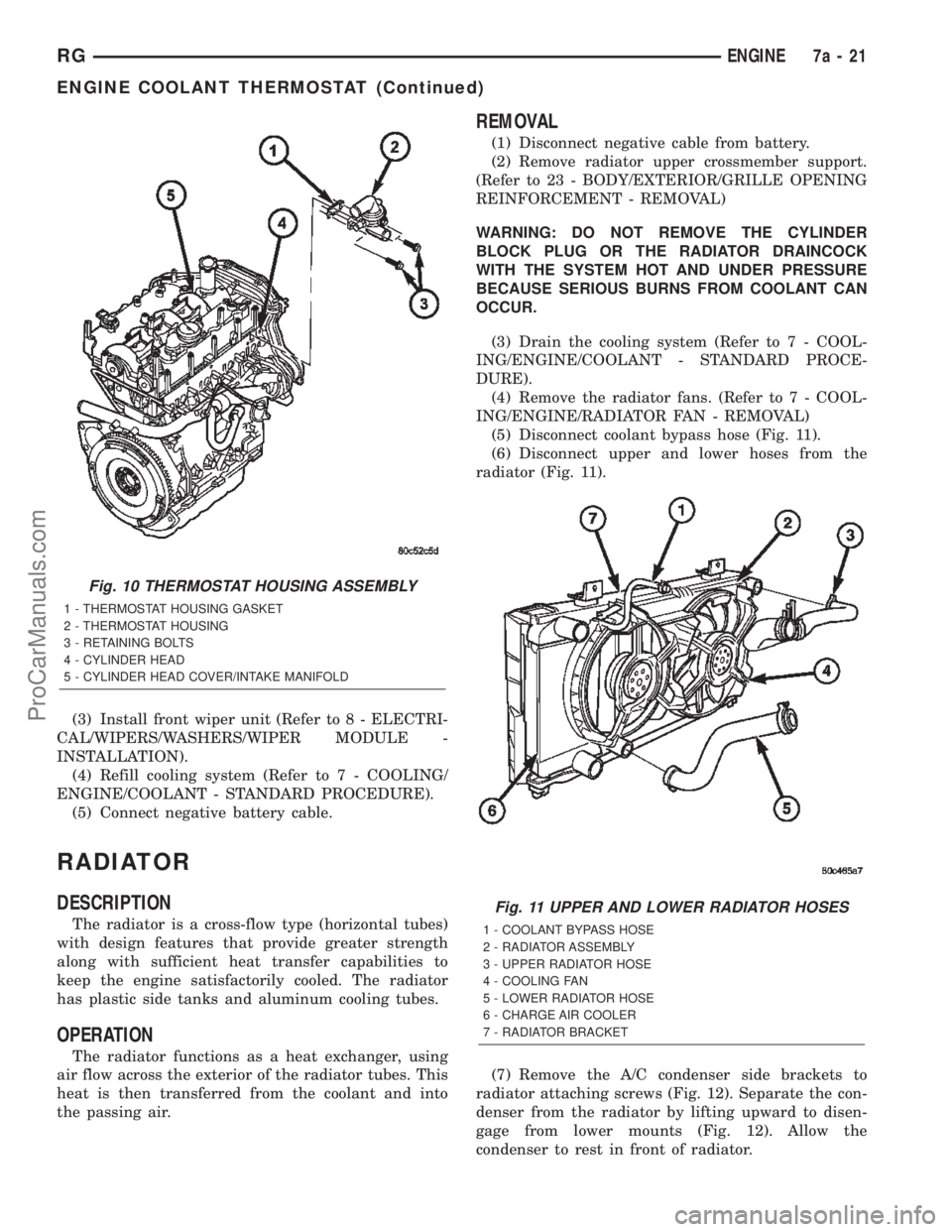
(5) Disconnect coolant bypass hose (Fig. 11).
(6) Disconnect upper and lower hoses from the
radiator (Fig. 11).
(7) Remove the A/C condenser side brackets to
radiator attaching screws (Fig. 12). Separate the con-
denser from the radiator by lifting upward to disen-
gage from lower mounts (Fig. 12). Allow the
condenser to rest in front of radiator.
Fig. 10 THERMOSTAT HOUSING ASSEMBLY
1 - THERMOSTAT HOUSING GASKET
2 - THERMOSTAT HOUSING
3 - RETAINING BOLTS
4 - CYLINDER HEAD
5 - CYLINDER HEAD COVER/INTAKE MANIFOLD
Fig. 11 UPPER AND LOWER RADIATOR HOSES
1 - COOLANT BYPASS HOSE
2 - RADIATOR ASSEMBLY
3 - UPPER RADIATOR HOSE
4 - COOLING FAN
5 - LOWER RADIATOR HOSE
6 - CHARGE AIR COOLER
7 - RADIATOR BRACKET
RGENGINE7a-21
ENGINE COOLANT THERMOSTAT (Continued)
ProCarManuals.com
Page 1204 of 2399
EXHAUST MANIFOLD
DESCRIPTION.........................62
OPERATION...........................62
REMOVAL.............................62
CLEANING............................62
INSPECTION..........................62
INSTALLATION.........................62
TIMING BELT COVER(S)
REMOVAL.............................63
INSTALLATION.........................63
TIMING BELT AND SPROCKET(S)
REMOVAL
REMOVAL - TIMING BELT...............64REMOVAL - CRANKSHAFT SPROCKET....66
CLEANING............................66
INSTALLATION
INSTALLATION - CRANKSHAFT SPROCKET . 66
INSTALLATION - TIMING BELT...........67
TIMING BELT TENSIONER & PULLEY
REMOVAL.............................68
INSTALLATION.........................69
BALANCE SHAFTS AND CARRIER ASSEMBLY
DESCRIPTION.........................69
OPERATION...........................70
REMOVAL.............................70
INSTALLATION.........................71
ENGINE 2.4L
DESCRIPTION
The 2.4 Liter (148 cu. in.) in-line four cylinder
engine is a double over head camshaft with hydraulic
lash adjusters and four valve per cylinder design.
The engine is free-wheeling; meaning it has provi-
sions for piston-to-valve clearance. However valve-to-
valve interference can occur, if camshafts are rotated
independently.
The cylinders are numbered from front of the
engine to the rear. The firing order is 1±3±4±2.
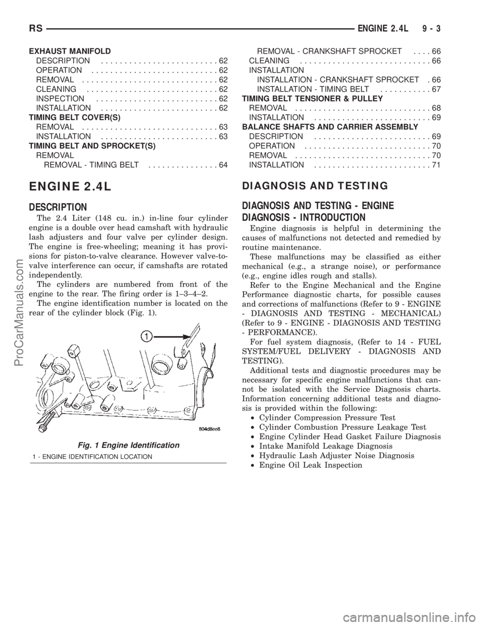
The engine identification number is located on the
rear of the cylinder block (Fig. 1).
DIAGNOSIS AND TESTING
DIAGNOSIS AND TESTING - ENGINE
DIAGNOSIS - INTRODUCTION
Engine diagnosis is helpful in determining the
causes of malfunctions not detected and remedied by
routine maintenance.
These malfunctions may be classified as either
mechanical (e.g., a strange noise), or performance
(e.g., engine idles rough and stalls).
Refer to the Engine Mechanical and the Engine
Performance diagnostic charts, for possible causes
and corrections of malfunctions (Refer to 9 - ENGINE
- DIAGNOSIS AND TESTING - MECHANICAL)
(Refer to 9 - ENGINE - DIAGNOSIS AND TESTING
- PERFORMANCE).
For fuel system diagnosis, (Refer to 14 - FUEL
SYSTEM/FUEL DELIVERY - DIAGNOSIS AND
TESTING).
Additional tests and diagnostic procedures may be
necessary for specific engine malfunctions that can-
not be isolated with the Service Diagnosis charts.
Information concerning additional tests and diagno-
sis is provided within the following:
²Cylinder Compression Pressure Test
²Cylinder Combustion Pressure Leakage Test
²Engine Cylinder Head Gasket Failure Diagnosis
²Intake Manifold Leakage Diagnosis
²Hydraulic Lash Adjuster Noise Diagnosis
²Engine Oil Leak Inspection
Fig. 1 Engine Identification
1 - ENGINE IDENTIFICATION LOCATION
RSENGINE 2.4L9-3
ProCarManuals.com
Page 1205 of 2399
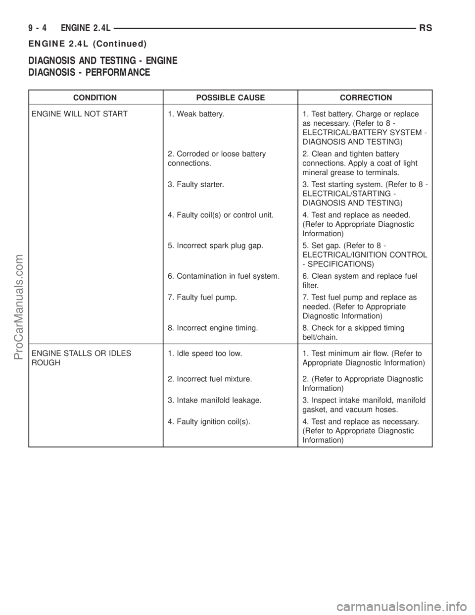
DIAGNOSIS AND TESTING - ENGINE
DIAGNOSIS - PERFORMANCE
CONDITION POSSIBLE CAUSE CORRECTION
ENGINE WILL NOT START 1. Weak battery. 1. Test battery. Charge or replace
as necessary. (Refer to 8 -
ELECTRICAL/BATTERY SYSTEM -
DIAGNOSIS AND TESTING)
2. Corroded or loose battery
connections.2. Clean and tighten battery
connections. Apply a coat of light
mineral grease to terminals.
3. Faulty starter. 3. Test starting system. (Refer to 8 -
ELECTRICAL/STARTING -
DIAGNOSIS AND TESTING)
4. Faulty coil(s) or control unit. 4. Test and replace as needed.
(Refer to Appropriate Diagnostic
Information)
5. Incorrect spark plug gap. 5. Set gap. (Refer to 8 -
ELECTRICAL/IGNITION CONTROL
- SPECIFICATIONS)
6. Contamination in fuel system. 6. Clean system and replace fuel
filter.
7. Faulty fuel pump. 7. Test fuel pump and replace as
needed. (Refer to Appropriate
Diagnostic Information)
8. Incorrect engine timing. 8. Check for a skipped timing
belt/chain.
ENGINE STALLS OR IDLES
ROUGH1. Idle speed too low. 1. Test minimum air flow. (Refer to
Appropriate Diagnostic Information)
2. Incorrect fuel mixture. 2. (Refer to Appropriate Diagnostic
Information)
3. Intake manifold leakage. 3. Inspect intake manifold, manifold
gasket, and vacuum hoses.
4. Faulty ignition coil(s). 4. Test and replace as necessary.
(Refer to Appropriate Diagnostic
Information)
9 - 4 ENGINE 2.4LRS
ENGINE 2.4L (Continued)
ProCarManuals.com
Page 1226 of 2399
Possible indications of the cylinder head gasket
leaking between adjacent cylinders are:
²Loss of engine power
²Engine misfiring
²Poor fuel economy
Possible indications of the cylinder head gasket
leaking between a cylinder and an adjacent water
jacket are:
²Engine overheating
²Loss of coolant
²Excessive steam (white smoke) emitting from
exhaust
²Coolant foaming
CYLINDER-TO-CYLINDER LEAKAGE TEST
To determine if an engine cylinder head gasket is
leaking between adjacent cylinders, follow the proce-
dures in Cylinder Compression Pressure Test (Refer
to 9 - ENGINE - DIAGNOSIS AND TESTING). An
engine cylinder head gasket leaking between adja-
cent cylinders will result in approximately a 50±70%
reduction in compression pressure.
CYLINDER-TO-WATER JACKET LEAKAGE TEST
WARNING: USE EXTREME CAUTION WHEN THE
ENGINE IS OPERATING WITH COOLANT PRES-
SURE CAP REMOVED.VISUAL TEST METHOD
With the engine cool, remove the coolant pressure
cap. Start the engine and allow it to warm up until
thermostat opens.
If a large combustion/compression pressure leak
exists, bubbles will be visible in the coolant.
COOLING SYSTEM TESTER METHOD
WARNING: WITH COOLING SYSTEM TESTER IN
PLACE, PRESSURE WILL BUILD UP FAST. EXCES-
SIVE PRESSURE BUILT UP, BY CONTINUOUS
ENGINE OPERATION, MUST BE RELEASED TO A
SAFE PRESSURE POINT. NEVER PERMIT PRES-
SURE TO EXCEED 138 kPa (20 psi).
Install Cooling System Tester 7700 or equivalent to
pressure cap neck. Start the engine and observe the
tester's pressure gauge. If gauge pulsates with every
power stroke of a cylinder a combustion pressure
leak is evident.
CHEMICAL TEST METHOD
Combustion leaks into the cooling system can also
be checked by using Bloc-Chek Kit C-3685-A or
equivalent. Perform test following the procedures
supplied with the tool kit.
REMOVAL - CYLINDER HEAD
(1) Perform fuel system pressure release procedure
before attempting any repairs.(Refer to 14 -
FUEL SYSTEM/FUEL DELIVERY - SPECIFICA-
TIONS)
(2) Disconnect battery negative cable.
(3) Drain cooling system. (Refer to 7 - COOLING -
STANDARD PROCEDURE)
(4) Remove air filter housing and inlet tube.
(5) Remove upper intake manifold. (Refer to 9 -
ENGINE/MANIFOLDS/INTAKE MANIFOLD -
REMOVAL)
(6) Remove heater tube support bracket from cyl-
inder head.
(7) Disconnect radiator upper and heater supply
hoses from intake manifold water outlet connections.
(8) Remove accessory drive belts. (Refer to 7 -
COOLING/ACCESSORY DRIVE/DRIVE BELTS -
REMOVAL)
(9) Raise vehicle and remove exhaust pipe from
manifold.
(10) Remove power steering pump reservoir and
line support bracket from lower intake manifold and
set aside. Do not disconnect lines.
(11) Remove ignition coil and wires from engine.
(12) Disconnect cam sensor and fuel injector wir-
ing connectors.
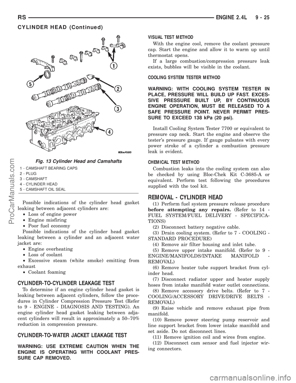
Fig. 13 Cylinder Head and Camshafts
1 - CAMSHAFT BEARING CAPS
2 - PLUG
3 - CAMSHAFT
4 - CYLINDER HEAD
5 - CAMSHAFT OIL SEAL
RSENGINE 2.4L9-25
CYLINDER HEAD (Continued)
ProCarManuals.com
Page 1228 of 2399

²Second All to 68 N´m (50 ft. lbs.)
²Third All to 68 N´m (50 ft. lbs.)
CAUTION: Do not use a torque wrench for the fol-
lowing step.
²Fourth Turn an additional 1/4 Turn,
(5) Install rocker arms. (Refer to 9 - ENGINE/
CYLINDER HEAD/ROCKER ARMS - INSTALLA-
TION)
(6) Install camshafts. (Refer to 9 - ENGINE/CYL-
INDER HEAD/CAMSHAFT(S) - INSTALLATION).
(7) Install cylinder head cover. (Refer to 9 -
ENGINE/CYLINDER HEAD/CYLINDER HEAD
COVER(S) - INSTALLATION)
(8) Install timing belt rear cover and timing belt
idler pulley. (Refer to 9 - ENGINE/VALVE TIMING/
TIMING BELT / CHAIN COVER(S) - INSTALLA-
TION)
(9) Install timing belt and camshaft sprockets.
(Refer to 9 - ENGINE/VALVE TIMING/TIMING
BELT/CHAIN AND SPROCKETS - INSTALLATION)
(10) Connect cam sensor and fuel injectors wiring
connectors.
(11) Install ignition coil and wires. Connect igni-
tion coil wiring connector.
(12) Install power steering pump reservoir and
line support bracket to cylinder head.
(13) Raise vehicle and install the exhaust pipe to
the manifold.
(14) Install accessory drive belts. (Refer to 7 -
COOLING/ACCESSORY DRIVE/DRIVE BELTS -
INSTALLATION)
(15) Install heater tube support bracket to cylinder
head.
(16) Connect radiator upper and heater hoses to
intake manifold water outlet connections.
(17) Install upper intake manifold. (Refer to 9 -
ENGINE/MANIFOLDS/INTAKE MANIFOLD -
INSTALLATION)
(18) Using new gaskets, install EGR tube and
tighten fasteners to 11 N´m (95 in. lbs.).
Fig. 16 Valve Guide Height
1 - VALVE GUIDE
2 - 13.25 - 13.75 MM
(.521 - .541 IN.)
3 - SPRING SEAT
Fig. 17 Checking Bolts for Stretching (Necking)
1 - STRETCHED BOLT
2 - THREADS ARE NOT STRAIGHT ON LINE
3 - THREADS ARE STRAIGHT ON LINE
4 - UNSTRETCHED BOLT
Fig. 18 Cylinder Head Gasket Positioning
1 - PART NUMBER FACES UP
2 - NO. 1 CYLINDER
Fig. 19 Cylinder Head Tightening Sequence
RSENGINE 2.4L9-27
CYLINDER HEAD (Continued)
ProCarManuals.com
Page 1232 of 2399
(7) Install cylinder head cover (Refer to 9 -
ENGINE/CYLINDER HEAD/CYLINDER HEAD
COVER - INSTALLATION).
(8) Install timing belt rear cover and camshaft
sprockets (Refer to 9 - ENGINE/VALVE TIMING/
TIMING BELT COVER(S) - INSTALLATION).
(9) Install timing belt (Refer to 9 - ENGINE/
VALVE TIMING/TIMING BELT AND SPROCKETS -
INSTALLATION).
CYLINDER HEAD COVER
REMOVAL
(1) Remove upper intake manifold. (Refer to 9 -
ENGINE/MANIFOLDS/INTAKE MANIFOLD -
REMOVAL)
(2) Remove upper manifold support bracket.
(3) Remove ignition coil and spark plug wires.
(4) Disconnect PCV and make-up air hoses from
cylinder head cover.
(5) Remove cylinder head cover bolts.
(6) Remove cylinder head cover from cylinder
head.
CLEANING
Clean cylinder head and cover mating surfaces
using a suitable solvent.
INSPECTION
Inspect cover rails for flatness.
INSTALLATION
NOTE: Replace spark plug well seals and bolt
assemblies when installing a new cylinder head
cover gasket.(1) Install new cylinder head cover gaskets and
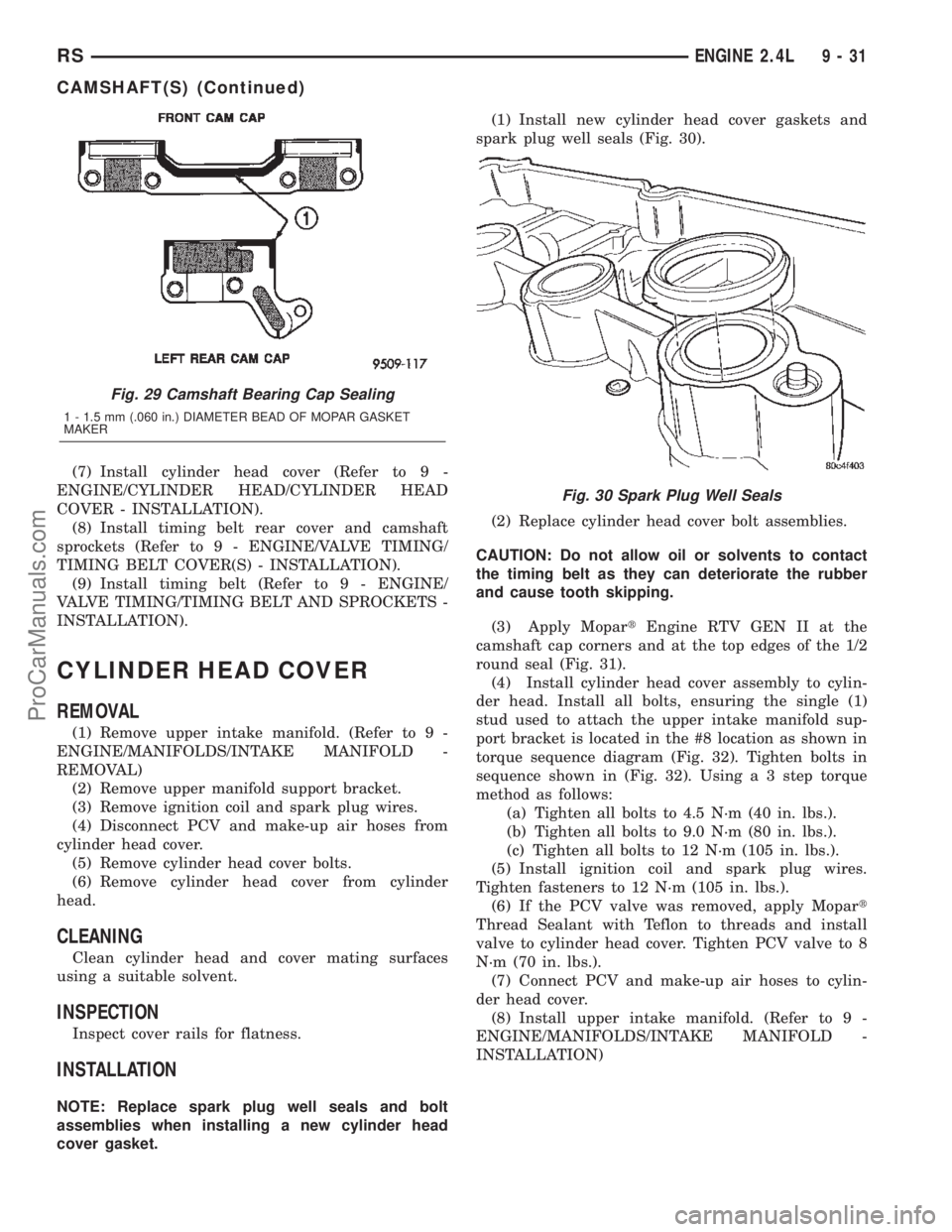
spark plug well seals (Fig. 30).
(2) Replace cylinder head cover bolt assemblies.
CAUTION: Do not allow oil or solvents to contact
the timing belt as they can deteriorate the rubber
and cause tooth skipping.
(3) Apply MopartEngine RTV GEN II at the
camshaft cap corners and at the top edges of the 1/2
round seal (Fig. 31).
(4) Install cylinder head cover assembly to cylin-
der head. Install all bolts, ensuring the single (1)
stud used to attach the upper intake manifold sup-
port bracket is located in the #8 location as shown in
torque sequence diagram (Fig. 32). Tighten bolts in
sequence shown in (Fig. 32). Using a 3 step torque
method as follows:
(a) Tighten all bolts to 4.5 N´m (40 in. lbs.).
(b) Tighten all bolts to 9.0 N´m (80 in. lbs.).
(c) Tighten all bolts to 12 N´m (105 in. lbs.).
(5) Install ignition coil and spark plug wires.
Tighten fasteners to 12 N´m (105 in. lbs.).
(6) If the PCV valve was removed, apply Mopart
Thread Sealant with Teflon to threads and install
valve to cylinder head cover. Tighten PCV valve to 8
N´m (70 in. lbs.).
(7) Connect PCV and make-up air hoses to cylin-
der head cover.
(8) Install upper intake manifold. (Refer to 9 -
ENGINE/MANIFOLDS/INTAKE MANIFOLD -
INSTALLATION)
Fig. 29 Camshaft Bearing Cap Sealing
1 - 1.5 mm (.060 in.) DIAMETER BEAD OF MOPAR GASKET
MAKER
Fig. 30 Spark Plug Well Seals
RSENGINE 2.4L9-31
CAMSHAFT(S) (Continued)
ProCarManuals.com
Page 1263 of 2399

²Coolant outlet connector bolts - 28 N´m (250 in.
lbs.)
²Coolant temperature sensor - 7 N´m (60 in. lbs.)
(1) Position a new gasket on cylinder head and
install lower manifold.
(2) Install and tighten intake manifold fasteners to
28 N´m (250 in. lbs.) in the sequence shown in (Fig.
110). Repeat procedure until all bolts are at specified
torque.
(3) Install lower intake manifold support bracket
bolts (Fig. 109) and tighten to:
²Bolts to intake 28 N´m (250 in. lbs.)
²Bolt to engine block 54 N´m (40 ft. lbs.)
(4) Position power steering reservoir on manifold
and install bolts.(5) Connect the fuel line. (Refer to 14 - FUEL SYS-
TEM/FUEL DELIVERY/QUICK CONNECT FIT-
TING - STANDARD PROCEDURE)
(6) Connect coolant temperature sensor/fuel injec-
tor wiring harness electrical connector.
(7) Install the radiator upper and heater supply
hoses.
(8) Install the upper intake manifold. (Refer to 9 -
ENGINE/MANIFOLDS/INTAKE MANIFOLD -
INSTALLATION)
(9) Fill the cooling system. (Refer to 7 - COOLING
- STANDARD PROCEDURE)
EXHAUST MANIFOLD
DESCRIPTION
The exhaust manifold is made of Hi-Silicone Moly
nodular cast iron for strength and high tempera-
tures. The manifold attaches to the cylinder head.
OPERATION
The exhaust manifold collects the exhaust gasses
exiting the combustion chambers. Then it channels
the exhaust gasses to the exhaust pipe attached to
the manifold.
REMOVAL
(1) Raise vehicle and disconnect exhaust pipe from
the exhaust manifold.
(2) Disconnect upstream oxygen sensor connector
at the rear of exhaust manifold.
(3) Remove the bolts attaching the manifold to the
cylinder head.
(4) Remove exhaust manifold.
(5) Inspect the manifold. (Refer to 9 - ENGINE/
MANIFOLDS/EXHAUST MANIFOLD - INSPEC-
TION)
CLEANING
(1) Discard gasket (if equipped) and clean all sur-
faces of manifold and cylinder head.
INSPECTION
(1) Inspect manifold gasket surfaces for flatness
with straight edge. Surface must be flat within 0.15
mm per 300 mm (0.006 in. per foot) of manifold
length.
(2) Inspect manifolds for cracks or distortion.
Replace manifold as necessary.
INSTALLATION
(1) Install exhaust manifold with a new gasket.
Tighten attaching nuts in the sequence shown in
(Fig. 111) to 19 N´m (170 in. lbs.).
Fig. 109 Lower Intake Manifold Support Bracket
1 - SUPPORT BRACKET
2 - BOLTS - UPPER TO MANIFOLD
3 - BOLT - LOWER TO ENGINE BLOCK
Fig. 110 Lower Intake Manifold Tightening Sequence
9 - 62 ENGINE 2.4LRS
INTAKE MANIFOLD - LOWER (Continued)
ProCarManuals.com
Page 1278 of 2399
DIAGNOSIS AND TESTING
DIAGNOSIS AND TESTING - ENGINE
DIAGNOSIS - INTRODUCTION
Engine diagnosis is helpful in determining the
causes of malfunctions not detected and remedied by
routine maintenance.
These malfunctions may be classified as either
mechanical (e.g., a strange noise), or performance
(e.g., engine idles rough and stalls).
Refer to the Engine Mechanical and the Engine
Performance diagnostic charts, for possible causes
and corrections of malfunctions (Refer to 9 - ENGINE
- DIAGNOSIS AND TESTING - MECHANICAL)
(Refer to 9 - ENGINE - DIAGNOSIS AND TESTING
- PERFORMANCE).
For fuel system diagnosis, (Refer to 14 - FUEL
SYSTEM/FUEL DELIVERY - DIAGNOSIS AND
TESTING).
Additional tests and diagnostic procedures may be
necessary for specific engine malfunctions that can-
not be isolated with the Service Diagnosis charts.
Information concerning additional tests and diagno-
sis is provided within the following:
²Cylinder Compression Pressure Test
²Cylinder Combustion Pressure Leakage Test
²Engine Cylinder Head Gasket Failure Diagnosis
²Intake Manifold Leakage Diagnosis
²Hydraulic Lash Adjuster Noise Diagnosis
²Engine Oil Leak Inspection
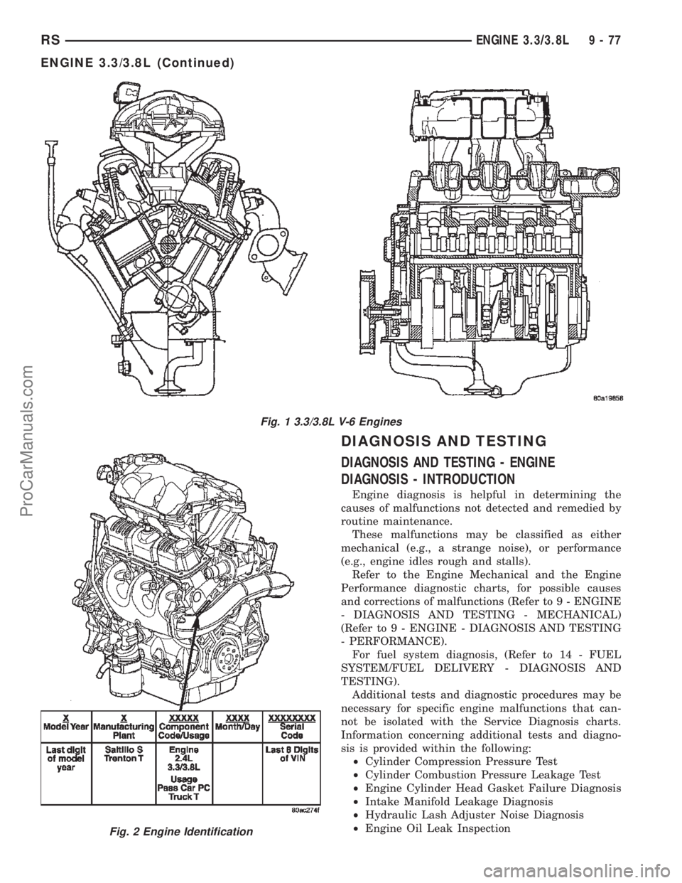
Fig. 1 3.3/3.8L V-6 Engines
Fig. 2 Engine Identification
RSENGINE 3.3/3.8L9-77
ENGINE 3.3/3.8L (Continued)
ProCarManuals.com