Rocker shaft CHRYSLER TOWN AND COUNTRY 2002 Service Manual
[x] Cancel search | Manufacturer: CHRYSLER, Model Year: 2002, Model line: TOWN AND COUNTRY, Model: CHRYSLER TOWN AND COUNTRY 2002Pages: 2399, PDF Size: 57.96 MB
Page 576 of 2399
(9) Remove side door lower sill plate. Refer to
Body for the procedure.
(10) Pull back the rearward edge of the B-pillar
trim to access the wire harness connector and discon-
nect connector.
(11) Remove the wire harness assembly from the
vehicle.
INSTALLATION
(1) Position the wire harness assembly in the vehi-
cle.
(2) Connect the wire harness connector located at
the rearward edge of the B-pillar.
(3) Install the side door lower sill plate. Refer to
the Body section for the procedure.
(4) Snap the wire harness retaining pushpins in
the rocker panel.
(5) Slide the wire harness on the lower drive unit
stud.
(6) Install the wire harness retaining clip on the
lower drive unit stud.
(7) Connect the power side door electrical connec-
tor, located just behind the lower drive unit.
(8) Install the lower drive unit cover and retaining
screws.(9) Install the appropriate door trim panel on the
sliding side door. Refer to the Body section for the
procedure.
(10) Connect the negative battery cable.
FLEX DRIVE
DESCRIPTION
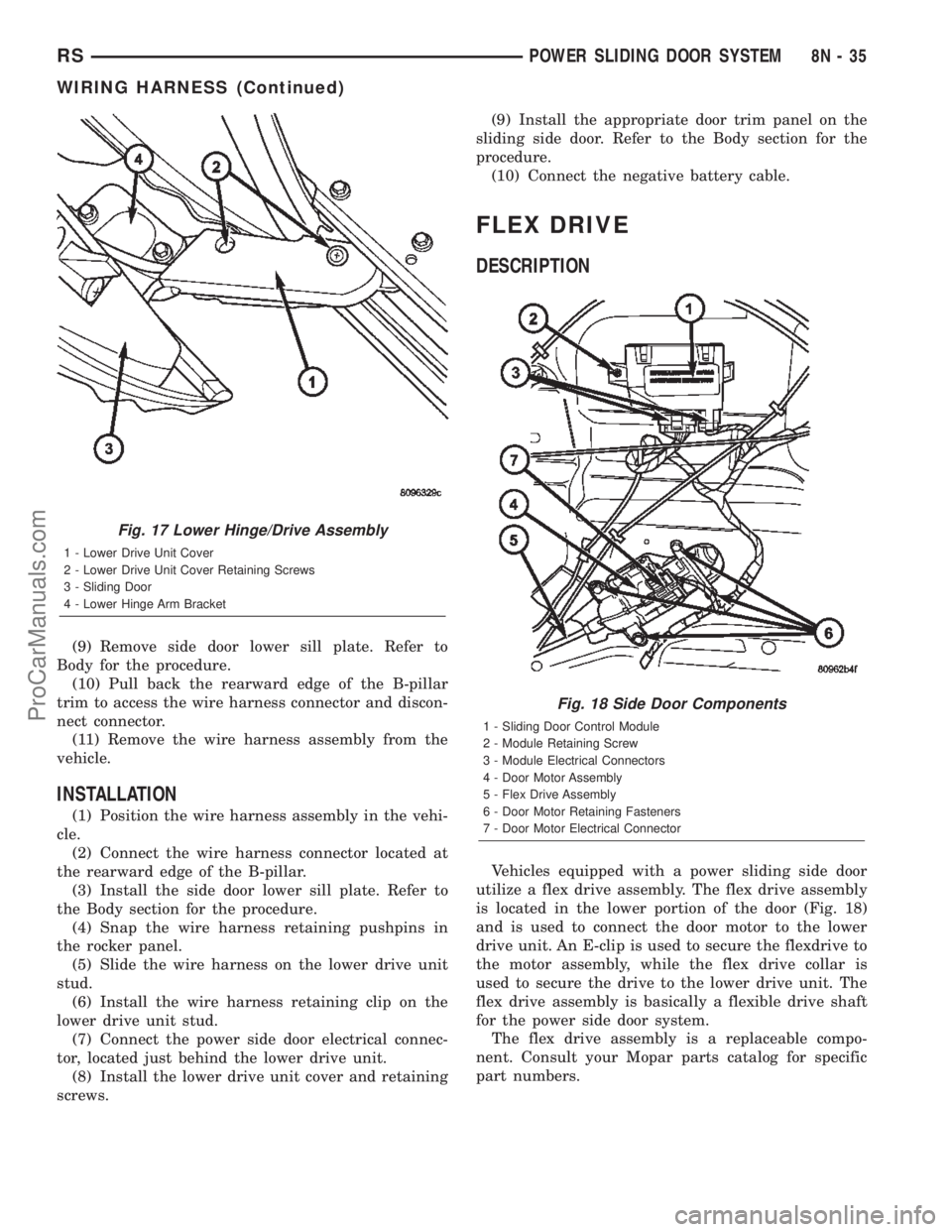
Vehicles equipped with a power sliding side door
utilize a flex drive assembly. The flex drive assembly
is located in the lower portion of the door (Fig. 18)
and is used to connect the door motor to the lower
drive unit. An E-clip is used to secure the flexdrive to
the motor assembly, while the flex drive collar is
used to secure the drive to the lower drive unit. The
flex drive assembly is basically a flexible drive shaft
for the power side door system.
The flex drive assembly is a replaceable compo-
nent. Consult your Mopar parts catalog for specific
part numbers.
Fig. 17 Lower Hinge/Drive Assembly
1 - Lower Drive Unit Cover
2 - Lower Drive Unit Cover Retaining Screws
3 - Sliding Door
4 - Lower Hinge Arm Bracket
Fig. 18 Side Door Components
1 - Sliding Door Control Module
2 - Module Retaining Screw
3 - Module Electrical Connectors
4 - Door Motor Assembly
5 - Flex Drive Assembly
6 - Door Motor Retaining Fasteners
7 - Door Motor Electrical Connector
RSPOWER SLIDING DOOR SYSTEM8N-35
WIRING HARNESS (Continued)
ProCarManuals.com
Page 1203 of 2399
VALVE SPRINGS & SEALS
REMOVAL
REMOVAL - CYLINDER HEAD ON.........32
REMOVAL - CYLINDER HEAD OFF........33
INSPECTION..........................33
INSTALLATION
INSTALLATION - CYLINDER HEAD ON.....33
INSTALLATION - CYLINDER HEAD OFF....33
HYDRAULIC LASH ADJUSTERS
DIAGNOSIS AND TESTING - HYDRAULIC
LASH ADJUSTER NOISE DIAGNOSIS......34
REMOVAL.............................34
INSTALLATION.........................34
ROCKER ARMS
REMOVAL.............................35
INSPECTION..........................35
INSTALLATION.........................35
ENGINE BLOCK
DESCRIPTION.........................35
STANDARD PROCEDURE
STANDARD PROCEDURE - PISTON TO
CYLINDER BORE FITTING..............36
STANDARD PROCEDURE - CYLINDER
BORE HONING.......................36
CLEANING............................37
INSPECTION..........................37
CONNECTING ROD BEARINGS
STANDARD PROCEDURE
CONNECTING ROD - FITTING...........37
CRANKSHAFT
DESCRIPTION.........................38
OPERATION...........................38
STANDARD PROCEDURE - CRANKSHAFT
ENDPLAY ...........................38
REMOVAL.............................38
INSPECTION..........................39
INSTALLATION.........................39
CRANKSHAFT MAIN BEARINGS
STANDARD PROCEDURE - MAIN BEARING -
FITTING.............................41
CRANKSHAFT OIL SEAL - FRONT
REMOVAL.............................42
INSTALLATION.........................43
CRANKSHAFT OIL SEAL - REAR
REMOVAL.............................43
INSTALLATION.........................44
PISTON & CONNECTING ROD
DESCRIPTION.........................45
OPERATION...........................45
REMOVAL.............................45
INSTALLATION.........................46
PISTON RINGS
STANDARD PROCEDURE
PISTON RING - FITTING................47
VIBRATION DAMPER
REMOVAL.............................48
INSTALLATION.........................48STRUCTURAL COLLAR
REMOVAL.............................49
INSTALLATION.........................49
ENGINE MOUNTING
DESCRIPTION.........................49
FRONT MOUNT
REMOVAL.............................49
INSTALLATION.........................50
LEFT MOUNT
REMOVAL.............................50
INSTALLATION.........................50
REAR MOUNT
REMOVAL.............................51
INSTALLATION.........................51
RIGHT MOUNT
REMOVAL.............................52
INSTALLATION.........................52
LUBRICATION
DESCRIPTION.........................53
OPERATION...........................53
DIAGNOSIS AND TESTING - CHECKING
ENGINE OIL PRESSURE................53
OIL
STANDARD PROCEDURE
ENGINE OIL LEVEL CHECK.............53
STANDARD PROCEDURE - ENGINE OIL
AND FILTER CHANGE..................54
OIL FILTER
DESCRIPTION.........................54
REMOVAL.............................54
INSTALLATION.........................55
OIL PAN
REMOVAL.............................55
INSTALLATION.........................55
OIL PRESSURE SWITCH
REMOVAL.............................55
INSTALLATION.........................55
OIL PUMP
REMOVAL.............................55
DISASSEMBLY.........................56
CLEANING............................57
INSPECTION..........................57
ASSEMBLY............................58
INSTALLATION.........................58
INTAKE MANIFOLD
DESCRIPTION.........................59
OPERATION...........................59
DIAGNOSIS AND TESTING - INTAKE
MANIFOLD LEAKS.....................59
INTAKE MANIFOLD - UPPER
REMOVAL.............................60
INSPECTION..........................61
INSTALLATION.........................61
INTAKE MANIFOLD - LOWER
REMOVAL.............................61
INSPECTION..........................61
INSTALLATION.........................61
9 - 2 ENGINE 2.4LRS
ProCarManuals.com
Page 1207 of 2399
DIAGNOSIS AND TESTING - ENGINE
DIAGNOSIS - MECHANICAL
CONDITION POSSIBLE CAUSES CORRECTION
NOISY VALVES 1. High or low oil level in
crankcase.1. Check and correct engine oil
level.
2. Thin or diluted oil. 2. Change oil to correct viscosity.
3. Thick oil 3. (a) Change engine oil and filter.
(b) Run engine to operating
temperature.
(c) Change engine oil and filter
again.
4. Low oil pressure. 4. Check and correct engine oil
pressure problem.
5. Dirt in hydraulic lifters/lash
adjusters.5. Replace hydraulic lifters/lash
adjusters.
6. Worn rocker arms. 6. Inspect oil supply to rocker arms.
7. Worn hydraulic lifters/lash
adjusters.7. Replace hydraulic lifters/lash
adjusters.
8. Worn valve guides. 8. Replace cylinder head assembly.
9. Excessive runout of valve seats
on valve faces.9. Grind valve seats and valves.
CONNECTING ROD NOISE 1. Insufficient oil supply. 1. Check engine oil level.
2. Low oil pressure. 2. Check engine oil level. Inspect oil
pump relief valve and spring.
3. Thin or diluted oil. 3. Change oil to correct viscosity.
4. Thick oil 4. (a) Change engine oil and filter.
(b) Run engine to operating
temperature.
(c) Change engine oil and filter
again.
5. Excessive bearing clearance. 5. Measure bearings for correct
clearance. Repair as necessary.
6. Connecting rod journal
out-of-round.6. Replace crankshaft or grind
surface.
7. Misaligned connecting rods. 7. Replace bent connecting rods.
9 - 6 ENGINE 2.4LRS
ENGINE 2.4L (Continued)
ProCarManuals.com
Page 1227 of 2399

(13) Remove timing belt and camshaft sprockets.
(Refer to 9 - ENGINE/VALVE TIMING/TIMING
BELT/CHAIN AND SPROCKETS - REMOVAL)
(14) Remove timing belt idler pulley and rear tim-
ing belt cover. (Refer to 9 - ENGINE/VALVE TIM-
ING/TIMING BELT / CHAIN COVER(S) -
REMOVAL)
(15) Remove cylinder head cover. (Refer to 9 -
ENGINE/CYLINDER HEAD/CYLINDER HEAD
COVER(S) - REMOVAL)
(16) Remove camshafts (Refer to 9 - ENGINE/
CYLINDER HEAD/CAMSHAFT(S) - REMOVAL).
NOTE: Identify rocker arm position to ensure cor-
rect re-installation in original position, if reused.
(17) Remove rocker arms. (Refer to 9 - ENGINE/
CYLINDER HEAD/ROCKER ARMS - REMOVAL)
(18) Remove cylinder head bolts in REVERSE
sequence of tightening (Fig. 19).
(19) Remove cylinder head from engine block.
(20) Inspect and clean cylinder head. (Refer to 9 -
ENGINE/CYLINDER HEAD - INSPECTION) (Refer
to 9 - ENGINE/CYLINDER HEAD - CLEANING)
CLEANING
To ensure engine gasket sealing, proper surface
preparation must be performed, especially with the
use of aluminum engine components and multi-layer
steel cylinder head gaskets.
NOTE: Multi-Layer Steel (MLS) head gaskets require
a scratch free sealing surface.
Remove all gasket material from cylinder head and
block (Refer to 9 - ENGINE - STANDARD PROCE-
DURE). Be careful not to gouge or scratch the alumi-
num head sealing surface.
Clean all engine oil passages.
INSPECTION
(1) Cylinder head must be flat within 0.1 mm
(0.004 in.) (Fig. 14).
(2) Inspect camshaft bearing journals for scoring.
(3) Remove carbon and varnish deposits from
inside of valve guides with a reliable guide cleaner.
(4) Using a small hole gauge and a micrometer,
measure valve guides in 3 places top, middle and bot-
tom (Fig. 15). (Refer to 9 - ENGINE - SPECIFICA-
TIONS) Replace guides if they are not within
specification.
(5) Check valve guide height (Fig. 16).
INSTALLATION - CYLINDER HEAD
NOTE: The Cylinder head bolts should be examined
BEFORE reuse. If the threads are necked down, the
bolts must be replaced (Fig. 17).
Necking can be checked by holding a scale or
straight edge against the threads. If all the threads
do not contact the scale, the bolt should be replaced.
(1) Before installing the bolts, the threads should
be coated with engine oil.
(2) Position cylinder head gasket on engine block
(Fig. 18).
(3) Install cylinder head on engine block.
(4) Tighten the cylinder head bolts in the sequence
shown in (Fig. 19). Using the 4 step torque turn
method, tighten according to the following values:
²First All to 34 N´m (25 ft. lbs.)
Fig. 14 Checking Cylinder Head Flatness
1 - FEELER GAUGE
2 - STRAIGHT EDGE
Fig. 15 Checking Wear on Valve GuideÐTypical
1-TOP
2 - MIDDLE
3 - BOTTOM
4 - CUT AWAY VIEW OF VALVE GUIDE MEASUREMENT
LOCATIONS
9 - 26 ENGINE 2.4LRS
CYLINDER HEAD (Continued)
ProCarManuals.com
Page 1228 of 2399

²Second All to 68 N´m (50 ft. lbs.)
²Third All to 68 N´m (50 ft. lbs.)
CAUTION: Do not use a torque wrench for the fol-
lowing step.
²Fourth Turn an additional 1/4 Turn,
(5) Install rocker arms. (Refer to 9 - ENGINE/
CYLINDER HEAD/ROCKER ARMS - INSTALLA-
TION)
(6) Install camshafts. (Refer to 9 - ENGINE/CYL-
INDER HEAD/CAMSHAFT(S) - INSTALLATION).
(7) Install cylinder head cover. (Refer to 9 -
ENGINE/CYLINDER HEAD/CYLINDER HEAD
COVER(S) - INSTALLATION)
(8) Install timing belt rear cover and timing belt
idler pulley. (Refer to 9 - ENGINE/VALVE TIMING/
TIMING BELT / CHAIN COVER(S) - INSTALLA-
TION)
(9) Install timing belt and camshaft sprockets.
(Refer to 9 - ENGINE/VALVE TIMING/TIMING
BELT/CHAIN AND SPROCKETS - INSTALLATION)
(10) Connect cam sensor and fuel injectors wiring
connectors.
(11) Install ignition coil and wires. Connect igni-
tion coil wiring connector.
(12) Install power steering pump reservoir and
line support bracket to cylinder head.
(13) Raise vehicle and install the exhaust pipe to
the manifold.
(14) Install accessory drive belts. (Refer to 7 -
COOLING/ACCESSORY DRIVE/DRIVE BELTS -
INSTALLATION)
(15) Install heater tube support bracket to cylinder
head.
(16) Connect radiator upper and heater hoses to
intake manifold water outlet connections.
(17) Install upper intake manifold. (Refer to 9 -
ENGINE/MANIFOLDS/INTAKE MANIFOLD -
INSTALLATION)
(18) Using new gaskets, install EGR tube and
tighten fasteners to 11 N´m (95 in. lbs.).
Fig. 16 Valve Guide Height
1 - VALVE GUIDE
2 - 13.25 - 13.75 MM
(.521 - .541 IN.)
3 - SPRING SEAT
Fig. 17 Checking Bolts for Stretching (Necking)
1 - STRETCHED BOLT
2 - THREADS ARE NOT STRAIGHT ON LINE
3 - THREADS ARE STRAIGHT ON LINE
4 - UNSTRETCHED BOLT
Fig. 18 Cylinder Head Gasket Positioning
1 - PART NUMBER FACES UP
2 - NO. 1 CYLINDER
Fig. 19 Cylinder Head Tightening Sequence
RSENGINE 2.4L9-27
CYLINDER HEAD (Continued)
ProCarManuals.com
Page 1230 of 2399

CAMSHAFT(S)
DESCRIPTION
Both camshafts have six bearing journal surfaces
and two cam lobes per cylinder (Fig. 23). Flanges at
the rear journals control camshaft end play. Provision
for a cam position sensor is located on the intake
camshaft on the rear of the cylinder head. A hydro-
dynamic oil seal is used for oil control at the front of
the camshaft.
OPERATION
The camshaft is driven by the crankshaft via drive
sprockets and belt. The camshaft has precisely
machined lobes to provide accurate valve timing and
duration.
STANDARD PROCEDURE - MEASURING
CAMSHAFT END PLAY
(1) Oil camshaft journals and install camshaft
WITHOUTrocker arms. Install rear cam caps and
tighten screws to specified torque.
(2) Using a suitable tool, move camshaft as far
rearward as it will go.
(3) Zero dial indicator (Fig. 24).
(4) Move camshaft as far forward as it will go.(5) Record reading on dial indicator. For end play
specification, (Refer to 9 - ENGINE - SPECIFICA-
TIONS).
(6) If end play is excessive, check cylinder head
and camshaft for wear; replace as necessary.
REMOVAL
(1) Remove cylinder head cover (Refer to 9 -
ENGINE/CYLINDER HEAD/CYLINDER HEAD
COVER - REMOVAL).
(2) Remove camshaft position sensor and camshaft
target magnet (Refer to 8 - ELECTRICAL/IGNITION
CONTROL/CAMSHAFT POSITION SENSOR -
REMOVAL).
(3) Remove timing belt (Refer to 9 - ENGINE/
VALVE TIMING/TIMING BELT AND SPROCKETS -
REMOVAL).
(4) Remove camshaft sprockets and timing belt
rear cover (Refer to 9 - ENGINE/VALVE TIMING/
TIMING BELT COVER(S) - REMOVAL).
(5) Bearing caps are identified for location.
Remove the outside bearing caps first (Fig. 25).
(6) Loosen the camshaft bearing cap attaching
fasteners in sequence shown (Fig. 26) one camshaft
at a time.
CAUTION: Camshafts are not interchangeable. The
intake cam number 6 thrust bearing face spacing is
wider.
(7) Identify the camshafts before removing from
the head. The camshafts are not interchangeable.
(8) Remove camshafts from cylinder head.
NOTE: If removing rocker arms, identify for reinstal-
lation in the original position.
CLEANING
Clean camshaft with a suitable solvent.
Fig. 23 Camshafts
1 - CAMSHAFT BEARING CAPS
2 - PLUG
3 - CAMSHAFT
4 - CYLINDER HEAD
5 - CAMSHAFT OIL SEAL
Fig. 24 Camshaft End Play - Typical
RSENGINE 2.4L9-29
ProCarManuals.com
Page 1231 of 2399

INSPECTION
(1) Inspect camshaft bearing journals for damage
and binding (Fig. 27). If journals are binding, check
the cylinder head for damage. Also check cylinder
head oil holes for clogging.
(2) Check the cam lobe and bearing surfaces for
abnormal wear and damage. Replace camshaft if
defective.
NOTE: If camshaft is replaced due to lobe wear or
damage, always replace the rocker arms.
(3) Measure the lobe actual wear (unworn area -
wear zone = actual wear) (Fig. 27) and replace cam-
shaft if out of limit. Standard value is 0.0254 mm
(0.001 in.), wearlimitis 0.254 mm (0.010 in.).
INSTALLATION
CAUTION: Ensure that NONE of the pistons are at
top dead center when installing the camshafts.(1) Lubricate all camshaft bearing journals, rocker
arms and camshaft lobes.
(2) Install all rocker arms in original positions, if
reused.
(3) Position camshafts on cylinder head bearing
journals. Install right and left camshaft bearing caps
No.2±5andright No. 6. Tighten M6 fasteners to 12
N´m (105 in. lbs.) in sequence shown in (Fig. 28).
(4) Apply MopartGasket Maker to No. 1 and No.
6 bearing caps (Fig. 29). Install bearing caps and
tighten M8 fasteners to 28 N´m (250 in. lbs.).
NOTE: Bearing end caps must be installed before
seals can be installed.
(5) Install camshaft oil seals (Refer to 9 -
ENGINE/CYLINDER HEAD/CAMSHAFT OIL
SEAL(S) - INSTALLATION).
(6) Install camshaft target magnet and camshaft
position sensor.
Fig. 25 Camshaft Bearing Cap Identification
Fig. 26 Camshaft Bearing Cap - Removal
1 - REMOVE OUTSIDE BEARING CAPS FIRST
Fig. 27 Checking Camshaft(s) for Wear
1 - UNWORN AREA
2 - ACTUAL WEAR
3 - BEARING JOURNAL
4 - LOBE
5 - WEAR ZONE
Fig. 28 Camshaft Bearing Cap Tightening Sequence
9 - 30 ENGINE 2.4LRS
CAMSHAFT(S) (Continued)
ProCarManuals.com
Page 1235 of 2399
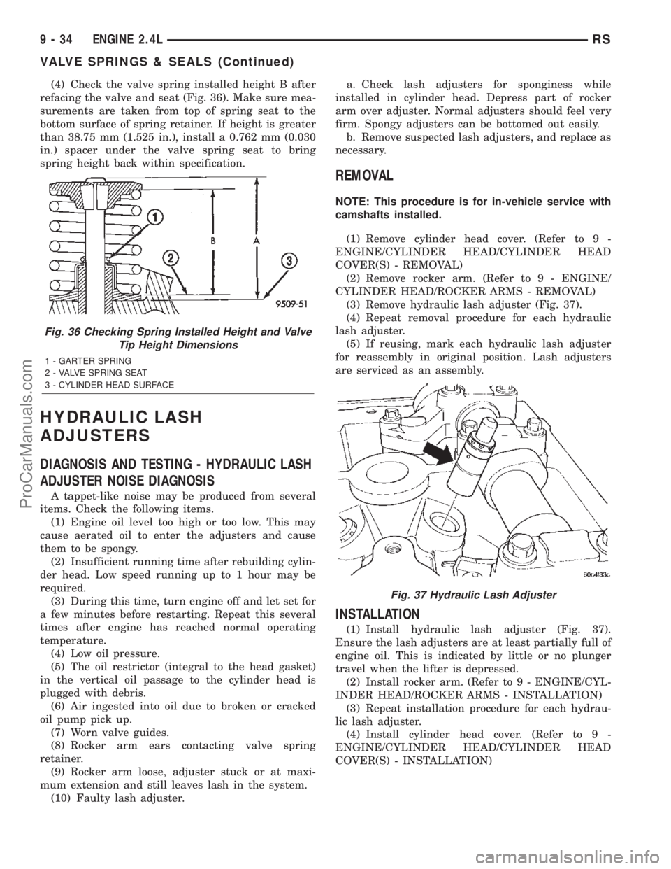
(4) Check the valve spring installed height B after
refacing the valve and seat (Fig. 36). Make sure mea-
surements are taken from top of spring seat to the
bottom surface of spring retainer. If height is greater
than 38.75 mm (1.525 in.), install a 0.762 mm (0.030
in.) spacer under the valve spring seat to bring
spring height back within specification.
HYDRAULIC LASH
ADJUSTERS
DIAGNOSIS AND TESTING - HYDRAULIC LASH
ADJUSTER NOISE DIAGNOSIS
A tappet-like noise may be produced from several
items. Check the following items.
(1) Engine oil level too high or too low. This may
cause aerated oil to enter the adjusters and cause
them to be spongy.
(2) Insufficient running time after rebuilding cylin-
der head. Low speed running up to 1 hour may be
required.
(3) During this time, turn engine off and let set for
a few minutes before restarting. Repeat this several
times after engine has reached normal operating
temperature.
(4) Low oil pressure.
(5) The oil restrictor (integral to the head gasket)
in the vertical oil passage to the cylinder head is
plugged with debris.
(6) Air ingested into oil due to broken or cracked
oil pump pick up.
(7) Worn valve guides.
(8) Rocker arm ears contacting valve spring
retainer.
(9) Rocker arm loose, adjuster stuck or at maxi-
mum extension and still leaves lash in the system.
(10) Faulty lash adjuster.a. Check lash adjusters for sponginess while
installed in cylinder head. Depress part of rocker
arm over adjuster. Normal adjusters should feel very
firm. Spongy adjusters can be bottomed out easily.
b. Remove suspected lash adjusters, and replace as
necessary.
REMOVAL
NOTE: This procedure is for in-vehicle service with
camshafts installed.
(1) Remove cylinder head cover. (Refer to 9 -
ENGINE/CYLINDER HEAD/CYLINDER HEAD
COVER(S) - REMOVAL)
(2) Remove rocker arm. (Refer to 9 - ENGINE/
CYLINDER HEAD/ROCKER ARMS - REMOVAL)
(3) Remove hydraulic lash adjuster (Fig. 37).
(4) Repeat removal procedure for each hydraulic
lash adjuster.
(5) If reusing, mark each hydraulic lash adjuster
for reassembly in original position. Lash adjusters
are serviced as an assembly.
INSTALLATION
(1) Install hydraulic lash adjuster (Fig. 37).
Ensure the lash adjusters are at least partially full of
engine oil. This is indicated by little or no plunger
travel when the lifter is depressed.
(2) Install rocker arm. (Refer to 9 - ENGINE/CYL-
INDER HEAD/ROCKER ARMS - INSTALLATION)
(3) Repeat installation procedure for each hydrau-
lic lash adjuster.
(4) Install cylinder head cover. (Refer to 9 -
ENGINE/CYLINDER HEAD/CYLINDER HEAD
COVER(S) - INSTALLATION)
Fig. 36 Checking Spring Installed Height and Valve
Tip Height Dimensions
1 - GARTER SPRING
2 - VALVE SPRING SEAT
3 - CYLINDER HEAD SURFACE
Fig. 37 Hydraulic Lash Adjuster
9 - 34 ENGINE 2.4LRS
VALVE SPRINGS & SEALS (Continued)
ProCarManuals.com
Page 1236 of 2399

ROCKER ARMS
REMOVAL
NOTE: This procedure is for in-vehicle service with
camshafts installed.
(1) Remove cylinder head cover. (Refer to 9 -
ENGINE/CYLINDER HEAD/CYLINDER HEAD
COVER(S) - REMOVAL)
(2) Remove spark plugs.
(3) Rotate engine until the camshaft lobe, on the
follower being removed, is positioned on its base cir-
cle (heel). Also, the piston should be a minimum of
6.3 mm (0.25 in) below TDC position.
CAUTION: If cam follower assemblies are to be
reused, always mark position for reassembly in
their original positions.
(4) Using Special Tools 8215A and 8436 slowly
depress valve assembly until rocker arm can be
removed (Fig. 38).
(5) Repeat removal procedure for each rocker arm.
INSPECTION
Inspect the rocker arm for wear or damage (Fig.
39). Replace as necessary.
INSTALLATION
(1) Lubricate rocker arm with clean engine oil.
(2) Using Special Tools 8215A and 8436 slowly
depress valve assembly until rocker arm can be
installed on the hydraulic lifter and valve stem (Fig.
38).
(3) Repeat installation procedure for each rocker
arm.
(4) Install spark plugs.
(5) Install cylinder head cover. (Refer to 9 -
ENGINE/CYLINDER HEAD/CYLINDER HEAD
COVER(S) - INSTALLATION)
ENGINE BLOCK
DESCRIPTION
The cast iron cylinder block is a two-piece assem-
bly, consisting of the cylinder block and bedplate (Fig.
40). The bedplate incorporates the main bearing caps
and bolts to the cylinder block. This design offers a
much stronger lower end and increased cylinder
block rigidity. The rear oil seal retainer is integral
with the block. The bedplate and block are serviced
as an assembly.
Fig. 38 Rocker Arm - Removal/Installation
1 - SPECIAL TOOL 8215A
2 - SPECIAL TOOL 8436
3 - 3/89DRIVE RACHET
Fig. 39 Rocker Arm
1 - TIP
2 - LASH ADJUSTER POCKET
3 - ROLLER
RSENGINE 2.4L9-35
ProCarManuals.com
Page 1275 of 2399
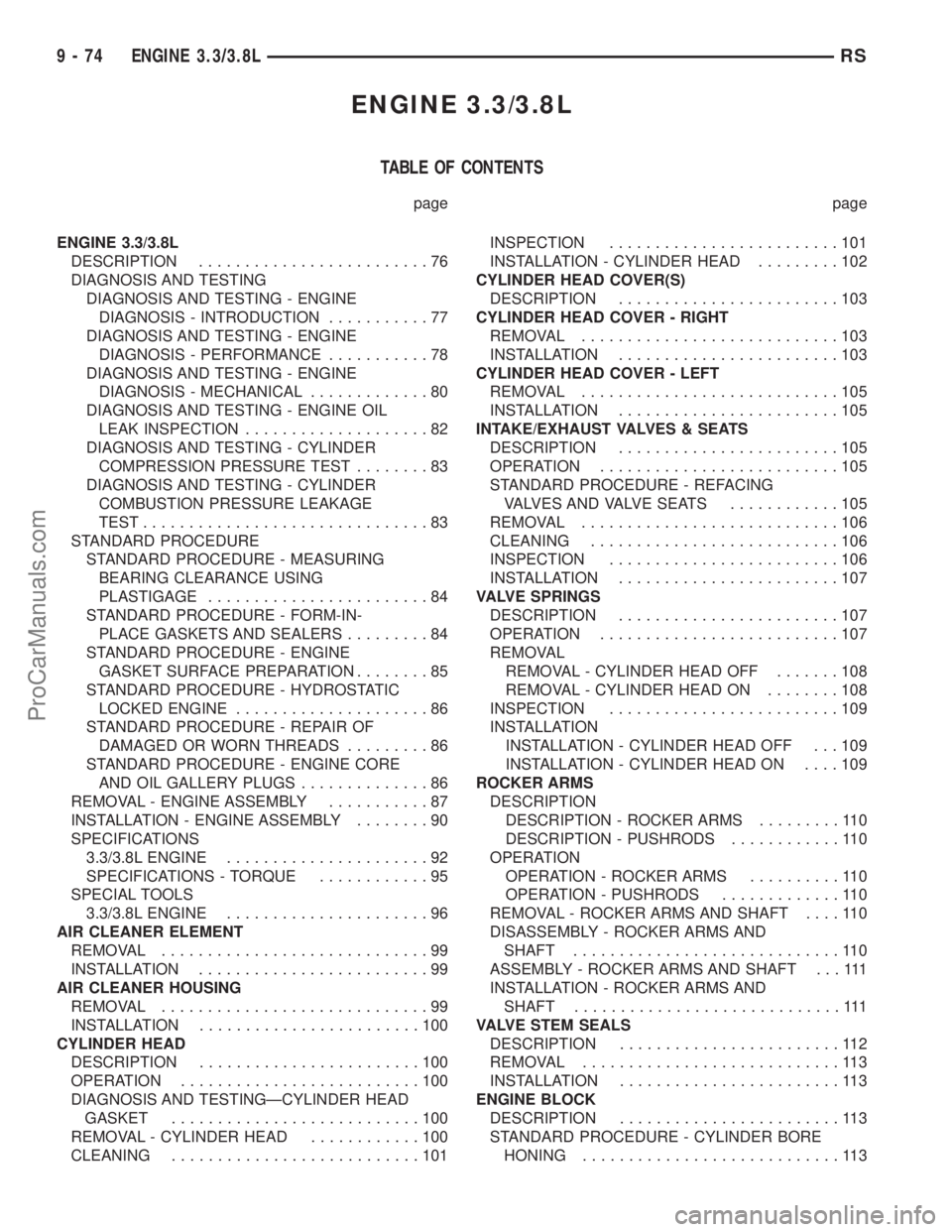
ENGINE 3.3/3.8L
TABLE OF CONTENTS
page page
ENGINE 3.3/3.8L
DESCRIPTION.........................76
DIAGNOSIS AND TESTING
DIAGNOSIS AND TESTING - ENGINE
DIAGNOSIS - INTRODUCTION...........77
DIAGNOSIS AND TESTING - ENGINE
DIAGNOSIS - PERFORMANCE...........78
DIAGNOSIS AND TESTING - ENGINE
DIAGNOSIS - MECHANICAL.............80
DIAGNOSIS AND TESTING - ENGINE OIL
LEAK INSPECTION....................82
DIAGNOSIS AND TESTING - CYLINDER
COMPRESSION PRESSURE TEST........83
DIAGNOSIS AND TESTING - CYLINDER
COMBUSTION PRESSURE LEAKAGE
TEST...............................83
STANDARD PROCEDURE
STANDARD PROCEDURE - MEASURING
BEARING CLEARANCE USING
PLASTIGAGE........................84
STANDARD PROCEDURE - FORM-IN-
PLACE GASKETS AND SEALERS.........84
STANDARD PROCEDURE - ENGINE
GASKET SURFACE PREPARATION........85
STANDARD PROCEDURE - HYDROSTATIC
LOCKED ENGINE.....................86
STANDARD PROCEDURE - REPAIR OF
DAMAGED OR WORN THREADS.........86
STANDARD PROCEDURE - ENGINE CORE
AND OIL GALLERY PLUGS..............86
REMOVAL - ENGINE ASSEMBLY...........87
INSTALLATION - ENGINE ASSEMBLY........90
SPECIFICATIONS
3.3/3.8L ENGINE......................92
SPECIFICATIONS - TORQUE............95
SPECIAL TOOLS
3.3/3.8L ENGINE......................96
AIR CLEANER ELEMENT
REMOVAL.............................99
INSTALLATION.........................99
AIR CLEANER HOUSING
REMOVAL.............................99
INSTALLATION........................100
CYLINDER HEAD
DESCRIPTION........................100
OPERATION..........................100
DIAGNOSIS AND TESTINGÐCYLINDER HEAD
GASKET...........................100
REMOVAL - CYLINDER HEAD............100
CLEANING...........................101INSPECTION.........................101
INSTALLATION - CYLINDER HEAD.........102
CYLINDER HEAD COVER(S)
DESCRIPTION........................103
CYLINDER HEAD COVER - RIGHT
REMOVAL............................103
INSTALLATION........................103
CYLINDER HEAD COVER - LEFT
REMOVAL............................105
INSTALLATION........................105
INTAKE/EXHAUST VALVES & SEATS
DESCRIPTION........................105
OPERATION..........................105
STANDARD PROCEDURE - REFACING
VALVESANDVALVESEATS ............105
REMOVAL............................106
CLEANING...........................106
INSPECTION.........................106
INSTALLATION........................107
VALVE SPRINGS
DESCRIPTION........................107
OPERATION..........................107
REMOVAL
REMOVAL - CYLINDER HEAD OFF.......108
REMOVAL - CYLINDER HEAD ON........108
INSPECTION.........................109
INSTALLATION
INSTALLATION - CYLINDER HEAD OFF . . . 109
INSTALLATION - CYLINDER HEAD ON....109
ROCKER ARMS
DESCRIPTION
DESCRIPTION - ROCKER ARMS.........110
DESCRIPTION - PUSHRODS............110
OPERATION
OPERATION - ROCKER ARMS..........110
OPERATION - PUSHRODS.............110
REMOVAL - ROCKER ARMS AND SHAFT....110
DISASSEMBLY - ROCKER ARMS AND
SHAFT.............................110
ASSEMBLY - ROCKER ARMS AND SHAFT . . . 111
INSTALLATION - ROCKER ARMS AND
SHAFT.............................111
VALVE STEM SEALS
DESCRIPTION........................112
REMOVAL............................113
INSTALLATION........................113
ENGINE BLOCK
DESCRIPTION........................113
STANDARD PROCEDURE - CYLINDER BORE
HONING............................113
9 - 74 ENGINE 3.3/3.8LRS
ProCarManuals.com