Windows motor CHRYSLER TOWN AND COUNTRY 2002 Service Manual
[x] Cancel search | Manufacturer: CHRYSLER, Model Year: 2002, Model line: TOWN AND COUNTRY, Model: CHRYSLER TOWN AND COUNTRY 2002Pages: 2399, PDF Size: 57.96 MB
Page 542 of 2399
POWER SYSTEMS
TABLE OF CONTENTS
page page
POWER LIFTGATE SYSTEM.................. 1
POWER SLIDING DOOR SYSTEM............ 18
POWER LOCKS........................... 39POWER MIRRORS........................ 46
POWER SEAT SYSTEM..................... 51
POWER WINDOWS........................ 64
POWER LIFTGATE SYSTEM
TABLE OF CONTENTS
page page
POWER LIFTGATE SYSTEM
DESCRIPTION..........................2
OPERATION............................3
DIAGNOSIS AND TESTING - POWER
LIFTGATE SYSTEM.....................4
STANDARD PROCEDURE
STANDARD PROCEDURE - LIFTGATE
ADJUSTMENT.........................8
STANDARD PROCEDURE - POWER
LIFTGATE LEARN CYCLE................9
PINCH SENSOR
DESCRIPTION..........................9
OPERATION............................9
REMOVAL.............................9
INSTALLATION..........................9
FULL OPEN SWITCH
DESCRIPTION.........................10
OPERATION...........................10
REMOVAL.............................10
INSTALLATION.........................10
LIFTGATE MOTOR
DESCRIPTION.........................10
OPERATION...........................11
REMOVAL.............................11
INSTALLATION.........................11
ENGAGE ACTUATOR
DESCRIPTION.........................11
OPERATION...........................11
REMOVAL.............................12
INSTALLATION.........................12TRANSVERSE BRACKET
DESCRIPTION.........................12
OPERATION...........................12
REMOVAL.............................13
INSTALLATION.........................13
LIFT GEAR & LINK ROD
DESCRIPTION.........................13
OPERATION...........................14
REMOVAL.............................14
INSTALLATION.........................14
LATCH
DESCRIPTION.........................14
OPERATION...........................15
REMOVAL.............................15
INSTALLATION.........................15
LATCH ACTUATOR
DESCRIPTION.........................15
OPERATION...........................15
REMOVAL.............................15
INSTALLATION.........................16
EXTERIOR HANDLE SWITCH
DESCRIPTION.........................16
OPERATION...........................16
REMOVAL.............................16
INSTALLATION.........................16
CHIME/THERMISTOR
DESCRIPTION.........................17
OPERATION...........................17
REMOVAL.............................17
INSTALLATION.........................17
RSPOWER SYSTEMS8N-1
ProCarManuals.com
Page 605 of 2399
POWER WINDOWS
TABLE OF CONTENTS
page page
POWER WINDOWS
DESCRIPTION.........................64
OPERATION...........................64
DIAGNOSIS AND TESTING - POWER
WINDOWS...........................64
VENT WINDOW MOTOR
DIAGNOSIS AND TESTING - VENT WINDOW
MOTOR .............................65
REMOVAL.............................65INSTALLATION.........................65
WINDOW MOTOR
REMOVAL.............................66
WINDOW SWITCH
DIAGNOSIS AND TESTING - WINDOW
SWITCH............................66
REMOVAL.............................67
INSTALLATION.........................67
POWER WINDOWS
DESCRIPTION
The Power Window System is activated through
switches mounted on the driver and passenger door
panels.
OPERATION
Front door window lift motors use permanent type
magnets. The B+ and ground applied at the motor
terminal pins will cause the motor to rotate in one
direction. Reversing current through the motor ter-
minals will cause the motor to rotate in the opposite
direction.
The power window motors ground through the
master switch in the driver door by a black wire
attached to the left cowl panel. Refer to the appropri-
ate wiring information. The wiring information
includes wiring diagrams, proper wire and connector
repair procedures, details of wire harness routing
and retention, connector pin-out information and
location views for the various wire harness connec-
tors, splices and grounds.
The power rear vent windows, if equipped, are
operated by switches mounted in the driver door
switch bezel. A separate switch is used for each win-
dow. Permanent magnet type motors connected to a
crank system are used to open and close the rear
vent windows. A battery positive and negative con-
nection to either of the two motor terminals will
cause the motor to rotate in one direction. Reversing
current through these same two connections will
cause the motor to rotate in the opposite direction.
Refer to the appropriate wiring information. The wir-
ing information includes wiring diagrams, proper
wire and connector repair procedures, details of wire
harness routing and retention, connector pin-outinformation and location views for the various wire
harness connectors, splices and grounds.
DIAGNOSIS AND TESTING - POWER
WINDOWS
POWER WINDOW MOTOR TEST
If the power window motor is receiving proper cur-
rent and ground and does not operate, proceed with
motor test. Refer to the appropriate wiring informa-
tion. The wiring information includes wiring dia-
grams, proper wire and connector repair procedures,
details of wire harness routing and retention, connec-
tor pin-out information and location views for the
various wire harness connectors, splices and grounds.
(1) Remove front door trim panel and sound pad as
necessary to gain access to power window motor wire
connector, (Refer to 23 - BODY/DOOR - FRONT/
TRIM PANEL - REMOVAL).
(2) Disconnect power window motor wire connector
from door harness.
(3) Using two jumper wires, connect one to a bat-
tery (+) source and the other to a good ground (-).
(4) Connect the Negative (-) jumper probe to one of
the motor connector terminals.
(5) Momentarily touch the Positive (+) jumper
probe to the other motor connector terminal.
When positive probe is connected the motor should
rotate in one direction to either move window up or
down. If window is all the way up or down the motor
will grunt and the inner door panel will flex when
actuated in that one direction.
(6) Reverse jumper probes at the motor connector
terminals and window should now move in opposite
direction. If window does not move or grunt, replace
the motor.
8N - 64 POWER WINDOWSRS
ProCarManuals.com
Page 606 of 2399
If window moved completely up or down, reverse
the jumper probes and cycle window to the opposite
position to verify full operation.
If motor grunts and does not move, verify that reg-
ulator is not binding.
WIRING VOLTAGE TEST
The following wiring test determines whether or
not voltage is continuous through the body harness
to switch.
(1) Remove the power window switch and bezel
assembly from the driver door. (Refer to 8 - ELEC-
TRICAL/POWER WINDOWS/POWER WINDOW
SWITCH - REMOVAL).
(2) Disconnect wire connector from back of power
window switch.
(3) Switch ignition ON position.
(4) Connect the clip end of a 12 volt test light to
Pin 13 in door harness connector at the window
switch. Touch the test light probe to Pin 9 and then
to Pin 11.
²If the test light illuminates, the wiring circuit
between the battery and switch is OK.
²If the lamp does not illuminate, first check the
25 amp circuit breaker attached to the electrical dis-
tribution wiring bracket. If the circuit breaker is OK,
then check the 40 amp fuse (#28) in the Integrated
Power Module (IPM). If both components are OK,
then check for a broken wire.
²Refer to the appropriate wiring information.
The wiring information includes wiring diagrams,
proper wire and connector repair procedures, details
of wire harness routing and retention, connector pin-
out information and location views for the various
wire harness connectors, splices and grounds.
VENT WINDOW MOTOR
DIAGNOSIS AND TESTING - VENT WINDOW
MOTOR
If the power vent window motor is receiving proper
current and ground and does not operate proceed
with motor test. Refer to the appropriate wiring
information. The wiring information includes wiring
diagrams, proper wire and connector repair proce-
dures, details of wire harness routing and retention,
connector pin-out information and location views for
the various wire harness connectors, splices and
grounds.
(1) Remove D-pillar trim panel necessary to gain
access to power vent window motor wire connector,
(Refer to 23 - BODY/INTERIOR/LEFT D-PILLAR
TRIM PANEL - REMOVAL) or (Refer to 23 - BODY/
INTERIOR/RIGHT D-PILLAR TRIM PANEL -
REMOVAL).(2) Disconnect power vent window motor wire con-
nector from body harness.
(3) Using two jumper wires, connect one to a bat-
tery (+) source and the other to a good ground (-).
(4) Connect the Negative (-) jumper probe to one of
the motor connector terminals.
(5) Momentarily touch the Positive (+) jumper
probe to the other motor connector terminal.
When positive probe is connected the motor should
rotate in one direction to either move window open or
closed. If window is all the way open or closed the
motor will grunt and the crank system will flex when
actuated in that one direction.
Reverse jumper probes at the motor connector ter-
minals and window should now move in opposite
direction. If window does not move or grunt, replace
the motor.
If window moved completely open or closed, reverse
the jumper probes and cycle window to the opposite
position to verify full operation.
If motor grunts and does not move, verify that
crank system is not binding.
REMOVAL
(1) Disconnect and isolate the battery negative
cable.
(2) Remove D-pillar trim panel. (Refer to 23 -
BODY/INTERIOR/LEFT D-PILLAR TRIM PANEL -
REMOVAL) or (Refer to 23 - BODY/INTERIOR/
RIGHT D-PILLAR TRIM PANEL - REMOVAL).
(3) Disconnect wire connector from power vent
motor.
(4) Using a flat bladed tool, carefully lift the circu-
lar actuator link tab. Remove link from window ball
socket.
(5) Remove bolts holding power vent motor to
D-pillar (Fig. 1).
(6) Remove power vent motor.
INSTALLATION
(1) Obtain new vent window motor.
(2) Snap the actuator link socket onto the quarter
window ball socket. Using a soft rubber mallet, push
the circular link tab flush with link surface.
(3) Install bolts holding power vent motor to D-pil-
lar.
(4) Reconnect wire connector to power vent motor.
(5) Reconnect the battery negative cable.
(6) Cycle quarter window open/close to verify func-
tion.
(7) Install D-pillar trim panel.
RSPOWER WINDOWS8N-65
POWER WINDOWS (Continued)
ProCarManuals.com
Page 607 of 2399
WINDOW MOTOR
REMOVAL
The window motor is incorporated into the window
regulator assembly. If the window motor requires
replacement, the window regulator must be replaced.
(Refer to 23 - BODY/DOOR - FRONT/WINDOW
REGULATOR - REMOVAL).
WINDOW SWITCH
DIAGNOSIS AND TESTING - WINDOW SWITCH
(1) Remove the desired switch to be tested from
the door trim panel. Driver's side (master) or passen-
ger side. (Refer to 8 - ELECTRICAL/POWER WIN-
DOWS/POWER WINDOW SWITCH - REMOVAL).
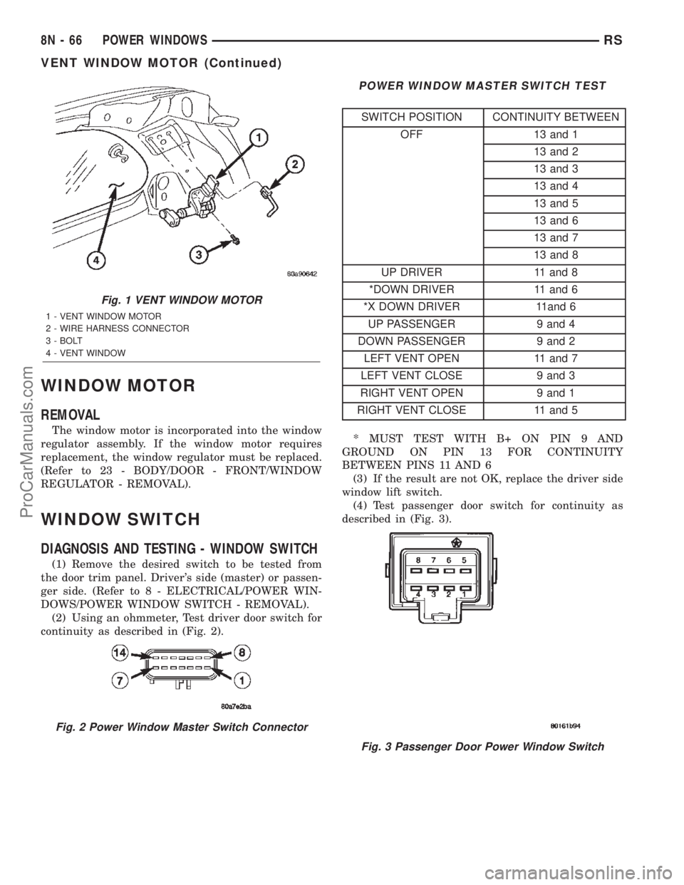
(2) Using an ohmmeter, Test driver door switch for
continuity as described in (Fig. 2).
POWER WINDOW MASTER SWITCH TEST
SWITCH POSITION CONTINUITY BETWEEN
OFF 13 and 1
13 and 2
13 and 3
13 and 4
13 and 5
13 and 6
13 and 7
13 and 8
UP DRIVER 11 and 8
*DOWN DRIVER 11 and 6
*X DOWN DRIVER 11and 6
UP PASSENGER 9 and 4
DOWN PASSENGER 9 and 2
LEFT VENT OPEN 11 and 7
LEFT VENT CLOSE 9 and 3
RIGHT VENT OPEN 9 and 1
RIGHT VENT CLOSE 11 and 5
* MUST TEST WITH B+ ON PIN 9 AND
GROUND ON PIN 13 FOR CONTINUITY
BETWEEN PINS 11 AND 6
(3) If the result are not OK, replace the driver side
window lift switch.
(4) Test passenger door switch for continuity as
described in (Fig. 3).
Fig. 1 VENT WINDOW MOTOR
1 - VENT WINDOW MOTOR
2 - WIRE HARNESS CONNECTOR
3 - BOLT
4 - VENT WINDOW
Fig. 2 Power Window Master Switch Connector
Fig. 3 Passenger Door Power Window Switch
8N - 66 POWER WINDOWSRS
VENT WINDOW MOTOR (Continued)
ProCarManuals.com
Page 608 of 2399

PASSENGER WINDOW SWITCH TEST
SWITCH POSITION CONTINUITY BETWEEN
OFF 3 AND 8
OFF 2 AND 5
UP 1 AND 8
DOWN 1 AND 5
(5) If the results are not OK, replace the switch.
The power window master switch has a Auto-Down
feature. The switch is equipped with two detent posi-
tions when actuating the power window OPEN. The
first detent position allows the window to roll down
and stop when the switch is released. The second
detent position actuates an integral express roll
down relay that rolls the window down after the
switch is released. When the express down circuit
senses stall current (window has reached end of
down travel), the switch will turn current off to the
motor. The AUTO feature can be cancelled by actuat-
ing the switch UP or DOWN while window is in
motion. If the electronic circuit in the switch fails to
detect a stall current, the auto down circuit will time
out within 9 to 13 seconds.
REMOVAL
(1) Disconnect and isolate the battery negative
cable.
(2) Using a trim stick, start at the bottom of the
switch and bezel assembly and pry up to remove the
switch and bezel assembly from the door trim panel
(Fig. 4).(3) Unlatch the locking tab on the harness side
connector of the switch.
(4) Disconnect wire harness connectors from
switch.
INSTALLATION
(1) Reconnect wire harness connector to switch.
(2) Insert switch into door trim panel and press
into place.
(3) Reconnect battery negative cable.
Fig. 4 POWER WINDOW SWITCH
1 - DOOR TRIM PANEL
2 - POWER WINDOW SWITCH AND BEZEL ASSEMBLY
RSPOWER WINDOWS8N-67
WINDOW SWITCH (Continued)
ProCarManuals.com
Page 978 of 2399

8W-60 POWER WINDOWS
Component Page
Accessory Relay..................... 8W-60-2
Driver Power Window Motor........ 8W-60-3, 4, 6
Driver Power Window Switch . . . 8W-60-3, 4, 5, 6, 7
Front Control Module................. 8W-60-2
Fuse 28............................ 8W-60-2
G300.......................... 8W-60-3, 4, 7
G301............................ 8W-60-5, 6Component Page
Integrated Power Module.............. 8W-60-2
Left Rear Vent Motor............... 8W-60-3, 6
Passenger Power Window Motor....... 8W-60-5, 7
Passenger Power Window Switch...... 8W-60-5, 7
Power Window Circuit Breaker.......... 8W-60-2
Power Window Switch............... 8W-60-4, 5
Right Rear Vent Motor.............. 8W-60-3, 6
RS8W-60 POWER WINDOWS8W-60-1
ProCarManuals.com
Page 2248 of 2399

control rear set temp button is pressed simulta-
neously with the rear control head, then the front
control head press events shall have priority, i.e. if
the front user presses Rear Set Temp down and the
rear user presses Set Temp up, then the rear set
temp will decrease.
DIAGNOSIS AND TESTING
DIAGNOSIS AND TESTING - A/C COOL DOWN
TEST
The heater-A/C control module can perform an A/C
cool down test, which is a test performed during the
manufacturing process to confirm that the air condi-
tioning system is performing satisfactorily. This test
can also provide a quick confirmation of air condi-
tioning system performance to the service technician.
If the test is completed satisfactorily, no further ser-
vice is required. If the test is failed, proceed to the
A/C Performance Test to confirm the a/c system is
operating properly, or use a DRBIIItscan tool to
diagnose the A/C system control and distribution sys-
tems. Refer to the appropriate diagnostic informa-
tion.
MANUAL TEMPERATURE CONTROL
The front blower speed and rear blower speed (if
equipped with rear HVAC) must be set to High and
the evaporator temperature sensor must be greater
than 55É F or the test will fail immediately. The test
is activated by depressing the A/C and PWR buttons
simultaneously and holding them depressed for no
less than five seconds. The PWR and A/C LEDs will
blink on and off until the test is complete. If the
LEDs stop blinking before two minutes, then the cool
down test has been completed successfully. If the two
minutes expire without the expansion valve temper-
ature reaching 20É F less than the outside air tem-
perature, then the cool down test has been failed and
further A/C system diagnosis is required. If the test
is failed, the LEDs will continue to blink until the
vehicle has been driven for greater than (8 miles).
AUTOMATIC TEMPERATURE CONTROL
The ambient air temperature in the room where
the vehicle will be tested must be a minimum of 21É
C (70ÉF) for this test. The test is activated by
depressing the A/C and PWR buttons simultaneously
and holding them depressed for no less than four sec-
onds. The snowflake icon and the DELAY text in the
ATC display will blink on and off alternately until
the test is complete. If the snowflake icon and the
DELAY text stop blinking before two minutes, then
the cool down test has been completed successfully. If
the two minutes expire without the evaporator tem-perature reaching 20É F less than the evaporator ini-
tial temperature, then the cool down test has been
failed and further A/C system diagnosis is required.
If the test is failed, the snowflake icon and the
DELAY text will continue to blink across ignition
cycles until the vehicle has been driven for greater
than (8 miles).
DIAGNOSIS AND TESTING - A/C
PERFORMANCE TEST
An air conditioning performance test is the best
way to determine whether the system is performing
up to standard. This test also provides valuable clues
as to the possible cause of trouble with the air con-
ditioning system. The ambient air temperature in the
location where the vehicle will be tested must be a
minimum of 21É C (70ÉF) for this test.
WARNING: REFER TO THE APPLICABLE WARN-
INGS AND CAUTIONS FOR THIS SYSTEM BEFORE
PERFORMING THE FOLLOWING OPERATION.
(Refer to 24 - HEATING & AIR CONDITIONING/
PLUMBING - FRONT - WARNING - A/C PLUMBING)
and (Refer to 24 - HEATING & AIR CONDITIONING/
PLUMBING - FRONT - CAUTION - A/C PLUMBING).
NOTE: When connecting the service equipment
coupling to the line fitting, verify that the valve of
the coupling is fully closed. This will reduce the
amount of effort required to make the connection.
(1) Connect a tachometer to monitor the engine
speed.
(2) Remove the caps from the refrigerant system
service ports and attach a manifold gauge set to
monitor the refrigerant system pressures.
(3) Set the heater-air conditioner controls so that
the compressor is engaged, the air within the vehicle
is being recirculated, the output air is directed
through the panel outlets, the temperature control is
in the full cool position, and the blower motor is oper-
ating at its highest speed.
(4) Start the engine and allow the engine to oper-
ate for about five minutes or until it reaches normal
operating temperature. Then hold the engine speed
at 1000 rpm with the compressor clutch engaged. If
the compressor clutch does not engage, proceed with
diagnosis of the compressor clutch coil. (Refer to 24 -
HEATING & AIR CONDITIONING/CONTROLS -
FRONT/COMPRESSOR CLUTCH COIL - DIAGNO-
SIS AND TESTING).
(5) Close all the vehicle windows and doors.
(6) Insert a thermometer in the left center panel
outlet and operate the engine for five minutes.
RSHEATING & AIR CONDITIONING24-5
HEATING & AIR CONDITIONING (Continued)
ProCarManuals.com
Page 2335 of 2399
²Single or Dual Zone (Front Unit Only - with
2.5L Turbo Diesel)0.91 kilograms (2.00 pounds or
32 ounces)
²Single or Dual Zone (Front Unit Only)- 0.96
kilograms (2.13 pounds or 34 ounces)
²Three Zone (Front and Rear Units)- 1.31
kilograms (2.88 pounds or 46 ounces)
CHARGING PROCEDURE
(1) Evacuate the refrigerant system. (Refer to 24 -
HEATING & AIR CONDITIONING/PLUMBING -
FRONT/REFRIGERANT - STANDARD PROCE-
DURE - REFRIGERANT SYSTEM EVACUATE).
(2) A manifold gauge set and a R-134a refrigerant
recovery/recycling/charging station that meets SAE
Standard J2210 should still be connected to the
refrigerant system.
(3) Measure the proper amount of refrigerant and
heat it to 52É C (125É F) with the charging station.
See the operating instructions supplied by the equip-
ment manufacturer for proper use of this equipment.
(4) Open both the suction and discharge valves,
then open the charge valve to allow the heated
refrigerant to flow into the system.
(5) When the transfer of refrigerant has stopped,
close both the suction and discharge valves.
(6) If all of the refrigerant charge did not transfer
from the dispensing device, open all of the windows
in the vehicle and set the heater-air conditioner con-
trols so that the compressor is engaged and the
blower motor is operating at its lowest speed setting.
Run the engine at a steady high idle (about 1400
rpm). If the compressor will not engage, test the com-
pressor clutch control circuit and repair as required.
(7) Open the suction valve to allow the remaining
refrigerant to transfer to the refrigerant system.
WARNING: TAKE CARE NOT TO OPEN THE DIS-
CHARGE (HIGH PRESSURE) VALVE AT THIS TIME.
(8) Close the suction valve and test the system
performance. (Refer to 24 - HEATING & AIR CON-
DITIONING - STANDARD PROCEDURE - A/C PER-
FORMANCE TEST).
(9) Disconnect the charging station and manifold
gauge set from the refrigerant system service ports.
(10) Reinstall the caps onto the refrigerant system
service ports.
(11) Run the HVAC Control Cooldown test to ver-
ify proper operation(Refer to 24 - HEATING & AIR
CONDITIONING - DIAGNOSIS AND TESTING).
STANDARD PROCEDURE - REFRIGERANT
SYSTEM EVACUATE
WARNING: REFER TO THE APPLICABLE WARN-
INGS AND CAUTIONS FOR THIS SYSTEM BEFOREPERFORMING THE FOLLOWING OPERATION.
(Refer to 24 - HEATING & AIR CONDITIONING/
PLUMBING - FRONT - WARNING - A/C PLUMBING)
and (Refer to 24 - HEATING & AIR CONDITIONING/
PLUMBING - FRONT - CAUTION - A/C PLUMBING).
If the refrigerant system has been open to the
atmosphere, it must be evacuated before the system
can be charged. If moisture and air enters the system
and becomes mixed with the refrigerant, the com-
pressor head pressure will rise above acceptable
operating levels. This will reduce the performance of
the air conditioner and damage the compressor.
Evacuating the refrigerant system will remove the
air and boil the moisture out of the system at near
room temperature. A R-134a refrigerant recovery/re-
cycling/charging station that meets SAE Standard
J2210 must be used to evacuate the refrigerant sys-
tem. See the operating instructions supplied by the
equipment manufacturer for proper care and use of
this equipment. To evacuate the refrigerant system,
use the following procedure:
NOTE: When connecting the service equipment
couplings to the refrigerant system service ports,
be certain that the valve of each coupling is fully
closed. This will reduce the amount of effort
required to make the connection.
(1) Remove the caps from the refrigerant system
service ports and attach a manifold gauge set and a
R-134a refrigerant recovery/recycling/charging sta-
tion that meets SAE Standard J2210 to the refriger-
ant system.
(2) Open both the suction and discharge valves
and start the charging station vacuum pump.
(3) When the suction gauge has read 88 kPa (26
in. Hg.) vacuum or greater for 45 minutes, close both
the suction and discharge valves and turn off the
vacuum pump. If the refrigerant system fails to
reach the specified vacuum, the system has a leak
that must be corrected. (Refer to 24 - HEATING &
AIR CONDITIONING/PLUMBING - FRONT/RE-
FRIGERANT - STANDARD PROCEDURE -
REFRIGERANT SYSTEM LEAKS).
(4) If the refrigerant system maintains the speci-
fied vacuum for thirty minutes, restart the vacuum
pump, open both the suction and discharge valves,
and evacuate the system for an additional ten min-
utes.
(5) Close both the suction and discharge valves,
and turn off the charging station vacuum pump.
(6) The refrigerant system is now ready to be
charged with R-134a refrigerant. (Refer to 24 -
HEATING & AIR CONDITIONING/PLUMBING -
FRONT/REFRIGERANT - STANDARD PROCE-
DURE - REFRIGERANT SYSTEM CHARGE).
24 - 92 PLUMBING - FRONTRS
REFRIGERANT (Continued)
ProCarManuals.com