air filter housing removal CHRYSLER TOWN AND COUNTRY 2002 Service Manual
[x] Cancel search | Manufacturer: CHRYSLER, Model Year: 2002, Model line: TOWN AND COUNTRY, Model: CHRYSLER TOWN AND COUNTRY 2002Pages: 2399, PDF Size: 57.96 MB
Page 1225 of 2399

AIR CLEANER ELEMENT
REMOVAL
(1) Unsnap 2 clips.
(2) Lift cover and pull toward the engine and
remove cover tabs from air box.
(3) Lift cover and remove the element (Fig. 11).
INSTALLATION
(1) Install the air filter element into air box (Fig.
11).
(2) Move cover so that the tabs insert into the air
box.
(3) Push cover down and snap the 2 clips.
AIR CLEANER HOUSING
REMOVAL
(1) Disconnect the negative battery cable.
(2) Disconnect the inlet air temperature sensor
(Fig. 12).
(3) Remove the inlet hose to throttle body (Fig. 11).
(4) Remove the bolt for air box at upper radiator
cross member.
(5) Pull air box up and off over the single locating
pin.
(6) Remove air box from vehicle
INSTALLATION
(1) Install air box into vehicle and onto the locat-
ing pin.(2) Install bolt to hold air box to the upper radia-
tor cross member.
(3) Install the inlet hose to the throttle body.
(4) Connect the inlet air temperature sensor (Fig.
12).
(5) Connect the negative battery cable.
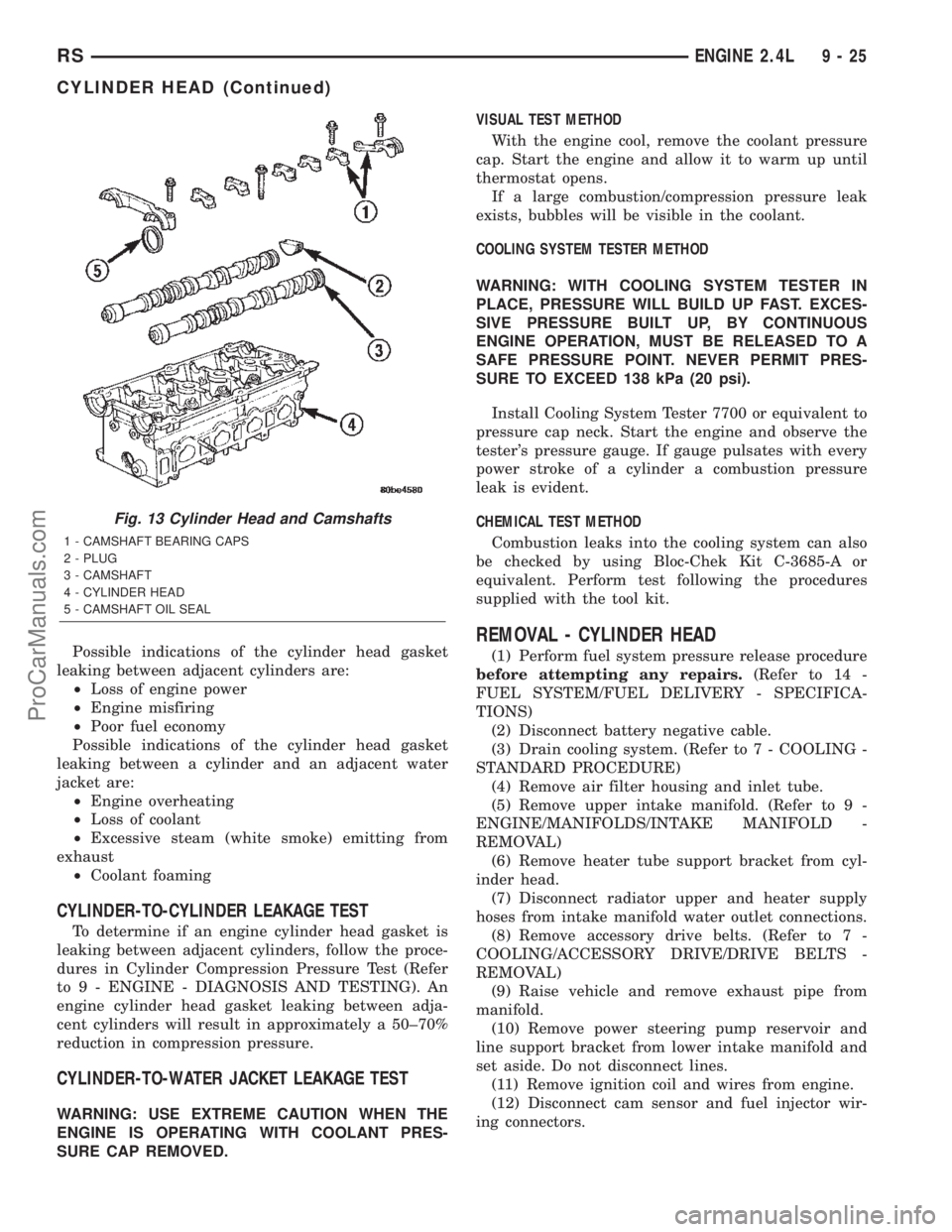
CYLINDER HEAD
DESCRIPTION
The cross flow designed, aluminum cylinder head
contains dual over-head camshafts with four valves
per cylinder (Fig. 13). The valves are arranged in two
in-line banks. The intake valves face toward the
front of the vehicle. The exhaust valves face the dash
panel. The cylinder head incorporates powdered
metal valve guides and seats. The cylinder head is
sealed to the block using a multi-layer steel head
gasket and retaining bolts.
Integral oil galleries provide lubrication passages
to the hydraulic lash adjusters, camshafts, and valve
mechanisms.
OPERATION
The cylinder head closes the combustion chamber,
allowing the pistons to compress the fuel/air mixture
for ignition. The valves are actuated by the lobe pro-
files on the camshaft to open and close at specified
duration to either allow clean air in the combustion
chamber or the exhaust gases out; depending on the
stroke of the engine.
DIAGNOSIS AND TESTINGÐCYLINDER HEAD
GASKET
A cylinder head gasket leak can be located between
adjacent cylinders or between a cylinder and the
adjacent water jacket.
Fig. 11 AIR BOX COVER
Fig. 12 IAT SENSOR 2.4L
9 - 24 ENGINE 2.4LRS
ProCarManuals.com
Page 1226 of 2399

Possible indications of the cylinder head gasket
leaking between adjacent cylinders are:
²Loss of engine power
²Engine misfiring
²Poor fuel economy
Possible indications of the cylinder head gasket
leaking between a cylinder and an adjacent water
jacket are:
²Engine overheating
²Loss of coolant
²Excessive steam (white smoke) emitting from
exhaust
²Coolant foaming
CYLINDER-TO-CYLINDER LEAKAGE TEST
To determine if an engine cylinder head gasket is
leaking between adjacent cylinders, follow the proce-
dures in Cylinder Compression Pressure Test (Refer
to 9 - ENGINE - DIAGNOSIS AND TESTING). An
engine cylinder head gasket leaking between adja-
cent cylinders will result in approximately a 50±70%
reduction in compression pressure.
CYLINDER-TO-WATER JACKET LEAKAGE TEST
WARNING: USE EXTREME CAUTION WHEN THE
ENGINE IS OPERATING WITH COOLANT PRES-
SURE CAP REMOVED.VISUAL TEST METHOD
With the engine cool, remove the coolant pressure
cap. Start the engine and allow it to warm up until
thermostat opens.
If a large combustion/compression pressure leak
exists, bubbles will be visible in the coolant.
COOLING SYSTEM TESTER METHOD
WARNING: WITH COOLING SYSTEM TESTER IN
PLACE, PRESSURE WILL BUILD UP FAST. EXCES-
SIVE PRESSURE BUILT UP, BY CONTINUOUS
ENGINE OPERATION, MUST BE RELEASED TO A
SAFE PRESSURE POINT. NEVER PERMIT PRES-
SURE TO EXCEED 138 kPa (20 psi).
Install Cooling System Tester 7700 or equivalent to
pressure cap neck. Start the engine and observe the
tester's pressure gauge. If gauge pulsates with every
power stroke of a cylinder a combustion pressure
leak is evident.
CHEMICAL TEST METHOD
Combustion leaks into the cooling system can also
be checked by using Bloc-Chek Kit C-3685-A or
equivalent. Perform test following the procedures
supplied with the tool kit.
REMOVAL - CYLINDER HEAD
(1) Perform fuel system pressure release procedure
before attempting any repairs.(Refer to 14 -
FUEL SYSTEM/FUEL DELIVERY - SPECIFICA-
TIONS)
(2) Disconnect battery negative cable.
(3) Drain cooling system. (Refer to 7 - COOLING -
STANDARD PROCEDURE)
(4) Remove air filter housing and inlet tube.
(5) Remove upper intake manifold. (Refer to 9 -
ENGINE/MANIFOLDS/INTAKE MANIFOLD -
REMOVAL)
(6) Remove heater tube support bracket from cyl-
inder head.
(7) Disconnect radiator upper and heater supply
hoses from intake manifold water outlet connections.
(8) Remove accessory drive belts. (Refer to 7 -
COOLING/ACCESSORY DRIVE/DRIVE BELTS -
REMOVAL)
(9) Raise vehicle and remove exhaust pipe from
manifold.
(10) Remove power steering pump reservoir and
line support bracket from lower intake manifold and
set aside. Do not disconnect lines.
(11) Remove ignition coil and wires from engine.
(12) Disconnect cam sensor and fuel injector wir-
ing connectors.
Fig. 13 Cylinder Head and Camshafts
1 - CAMSHAFT BEARING CAPS
2 - PLUG
3 - CAMSHAFT
4 - CYLINDER HEAD
5 - CAMSHAFT OIL SEAL
RSENGINE 2.4L9-25
CYLINDER HEAD (Continued)
ProCarManuals.com
Page 1300 of 2399

AIR CLEANER ELEMENT
REMOVAL
(1) Unsnap 2 clips.
(2) Lift cover and pull toward the engine and
remove cover tabs from air box.
(3) Lift cover and remove the element (Fig. 15).
INSTALLATION
(1) Install the air filter element into air box (Fig.
15).
(2) Move cover so that the tabs insert into the air
box.
(3) Push cover down and snap the 2 clips.
AIR CLEANER HOUSING
REMOVAL
(1) Disconnect the negative battery cable.
(2) Disconnect the inlet air temperature sensor
(Fig. 16).
(3) Remove the inlet hose to throttle body.
(4) Remove the bolt for air box at upper radiator
cross member.
(5) Pull air box up and off over the single locating
pin.
(6) Remove air box from vehicle
Pressure Transducer CH7059
Compression Test Adapter 8116
DRB IIITwith PEP Module OT-CH6010A
Fig. 15 AIR BOX COVER
Fig. 16 Inlet Air Temperature Sensor
RSENGINE 3.3/3.8L9-99
ENGINE 3.3/3.8L (Continued)
ProCarManuals.com
Page 1338 of 2399

RIGHT MOUNT
REMOVAL
(1) Remove air cleaner housing lid and clean air
hose from throttle body.
(2) Remove air cleaner element and housing.
(3) Disconnect make-up air hose from cylinder
head cover.
(4) Remove the load on the right engine mount by
carefully supporting the engine assembly with a floor
jack.
(5) Disconnect electrical harness support clips from
engine mount bracket.
(6) Remove the bolts attaching the engine mount
to the frame rail (Fig. 99).
(7) Remove the three bolts attaching the engine
mount to the engine bracket (Fig. 99).
(8) Remove the right engine mount (Fig. 99).
INSTALLATION
(1) Install engine bracket (if removed). Tighten
bolts to 33 N´m (24 ft. lbs.).
(2) Position right engine mount and install frame
rail to mount bolts (Fig. 99). Tighten bolts to 68 N´m
(50 ft. lbs.).
(3) Install the mount to engine bracket bolts and
tighten to 54 N´m (40 ft. lbs.). (Fig. 99)
(4) Connect electrical harness support clips to
engine mount bracket.
(5) Remove jack from under engine.
(6) Connect make-up air hose to cylinder head
cover.
(7) Install air cleaner housing and element.
(8) Install air cleaner housing lid and clean air
tube to throttle body.
LUBRICATION
DESCRIPTION
The lubrication system is a full flow filtration pres-
sure feed type. The oil pump is mounted in the tim-
ing chain cover and is driven by the crankshaft
OPERATION
Oil from the oil pan is pumped by a internal gear
type oil pump directly coupled to the crankshaft. The
pressure is regulated by a relief valve located in the
timing chain cover. The oil is pumped through an oil
filter and feeds a main oil gallery. This oil gallery
feeds oil under pressure to the main and rod bear-
ings, camshaft bearings. Passages in the cylinder
block feed oil to the hydraulic lifters and rocker shaft
brackets which feeds the rocker arm pivots (Fig.
100).
DIAGNOSIS AND TESTING - ENGINE OIL
PRESSURE
(1) Disconnect and remove oil pressure switch
(Refer to 9 - ENGINE/LUBRICATION/OIL PRES-
SURE SENSOR/SWITCH - REMOVAL).
(2) Install Special Tools C-3292 Gauge with 8406
Adaptor. For Special Tool identification, (Refer to 9 -
ENGINE - SPECIAL TOOLS).
(3) Start engine and record oil pressure. Refer to
Oil Pressure in Engine Specifications for the correct
pressure (Refer to 9 - ENGINE - SPECIFICATIONS).
Fig. 99 Right Engine Mount
1 - RIGHT ENGINE MOUNT
2 - BOLT - MOUNT TO FRAME RAIL
3 - BOLT - MOUNT TO ENGINE
4 - ENGINE MOUNT BRACKET
5 - RIGHT FRAME RAIL
RSENGINE 3.3/3.8L9 - 137
ProCarManuals.com
Page 1493 of 2399

Refer to the maintenance schedules for the recom-
mended fuel filter replacement intervals.
For draining of water from canister, refer to Fuel
Filter/Water Separator Removal/Installation section.
A Water-In-Fuel (WIF) sensor is part of the fuel fil-
ter cap. Refer to Water-In-Fuel Sensor Description/
Operation.
The fuel heater is installed into the filter/separator
housing above the fuel filter. Refer to Fuel Heater
Description/Operation.
FUEL LINES
DESCRIPTION
DESCRIPTION
All fuel lines up to the fuel injection pump are con-
sidered low-pressure. This includes the fuel lines
from: the fuel tank to the fuel transfer pump, and
the fuel transfer pump to the fuel injection pump.
The fuel return lines and the fuel drain lines are also
considered low-pressure lines. High-pressure lines
are used between the fuel injection pump and the
fuel injectors. Also refer to High-Pressure Fuel Lines
Description/Operation.
DESCRIPTION - HIGH PRESSURE FUEL LINES
The high-pressure fuel lines are the 4 lines located
between the fuel injection pump and the fuel injec-
torsctor tubes. All other fuel lines are considered low-
pressure lines.
OPERATION - HIGH PRESSURE FUEL LINES
CAUTION: The high-pressure fuel lines cannot con-
tact each other or other components. Do not
attempt to weld high-pressure fuel lines or to repair
lines that are damaged. If lines are ever kinked or
bent, they must be replaced. Use only the recom-
mended lines when replacement of high-pressure
fuel line is necessary.
High-pressure fuel lines deliver fuel under
extremely high pressure from the injection pump to
the fuel injectors. The lines expand and contract from
the high-pressure fuel pulses generated during the
injection process. All high-pressure fuel lines are of
the same length and inside diameter. Correct high-
pressure fuel line usage and installation is critical to
smooth engine operation.
WARNING: USE EXTREME CAUTION WHEN
INSPECTING FOR HIGH-PRESSURE FUEL LEAKS.
INSPECT FOR HIGH-PRESSURE FUEL LEAKS WITH
A SHEET OF CARDBOARD. HIGH FUEL INJECTIONPRESSURE CAN CAUSE PERSONAL INJURY IF
CONTACT IS MADE WITH THE SKIN.
DIAGNOSIS AND TESTING - HIGH PRESSURE
FUEL LINES
High-pressure fuel line leaks can cause starting
problems and poor engine performance.
WARNING: DUE TO EXTREME FUEL PRESSURES,
USE EXTREME CAUTION WHEN INSPECTING FOR
HIGH-PRESSURE FUEL LEAKS. DO NOT GET YOUR
HAND NEAR A SUSPECTED LEAK. INSPECT FOR
HIGH-PRESSURE FUEL LEAKS WITH A SHEET OF
CARDBOARD. HIGH FUEL INJECTION PRESSURE
CAN CAUSE PERSONAL INJURY IF CONTACT IS
MADE WITH THE SKIN.
Start the engine. Move the cardboard over the
high-pressure fuel lines and check for fuel spray onto
the cardboard (Fig. 4). If a high-pressure line connec-
tion is leaking, bleed the system and tighten the con-
nection. Refer to the Air Bleed Procedure in this
group for procedures. Replace damaged, restricted or
leaking high-pressure fuel lines with the correct
replacement line.
Fig. 4 Typical Test for Leaks with Cardboard
1 - HIGH-PRESSURE LINE
2 - CARDBOARD
3 - FITTING
14a - 6 FUEL DELIVERYRG
FUEL FILTER / WATER SEPARATOR (Continued)
ProCarManuals.com
Page 1494 of 2399

CAUTION: The high-pressure fuel lines cannot con-
tact each other or other components. Do not
attempt to weld high-pressure fuel lines or to repair
lines that are damaged. Only use the recommended
lines when replacement of high-pressure fuel line is
necessary.
FUEL TRANSFER PUMP
DESCRIPTION
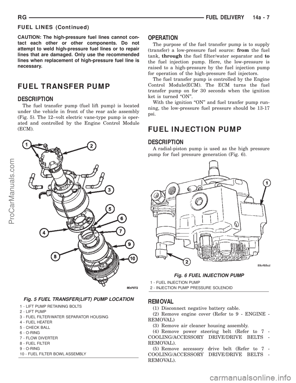
The fuel transfer pump (fuel lift pump) is located
under the vehicle in front of the rear axle assembly
(Fig. 5). The 12±volt electric vane-type pump is oper-
ated and controlled by the Engine Control Module
(ECM).
OPERATION
The purpose of the fuel transfer pump is to supply
(transfer) a low-pressure fuel source:fromthe fuel
tank,throughthe fuel filter/water separator andto
the fuel injection pump. Here, the low-pressure is
raised to a high-pressure by the fuel injection pump
for operation of the high-pressure fuel injectors.
The fuel transfer pump is controlled by the Engine
Control Module(ECM). The ECM turns the fuel
transfer pump on for 30 seconds when the ignition
ket is turned ªONº.
With the ignition ªONº and fuel tranfer pump run-
ning, the low-pressure fuel pressure should be 13-17
psi.
FUEL INJECTION PUMP
DESCRIPTION
A radial-piston pump is used as the high pressure
pump for fuel pressure generation (Fig. 6).
REMOVAL
(1) Disconnect negative battery cable.
(2) Remove engine cover (Refer to 9 - ENGINE -
REMOVAL)
(3) Remove air cleaner housing assembly.
(4) Remove power steering belt (Refer to 7 -
COOLING/ACCESSORY DRIVE/DRIVE BELTS -
REMOVAL).
(5) Remove accessory drive belt (Refer to 7 -
COOLING/ACCESSORY DRIVE/DRIVE BELTS -
REMOVAL).
Fig. 5 FUEL TRANSFER(LIFT) PUMP LOCATION
1 - LIFT PUMP RETAINING BOLTS
2 - LIFT PUMP
3 - FUEL FILTER/WATER SEPARATOR HOUSING
4 - FUEL HEATER
5 - CHECK BALL
6 - O-RING
7 - FLOW DIVERTER
8 - FUEL FILTER
9 - O-RING
10 - FUEL FILTER BOWL ASSEMBLY
Fig. 6 FUEL INJECTION PUMP
1 - FUEL INJECTION PUMP
2 - INJECTION PUMP PRESSURE SOLENOID
RGFUEL DELIVERY14a-7
FUEL LINES (Continued)
ProCarManuals.com
Page 1503 of 2399

MASS AIR FLOW (MAF)
SENSOR
DESCRIPTION
The Mass Air Flow (MAF) Sensor is mounted
inline in the air intake between the air filter and the
turbocharger (Fig. 8).
OPERATION
The ECM uses the mass air flow (MAF) sensor to
measure air density. The MAF sensor contains a
ceramic element. A signal voltage is provided to the
element. As engine speed increases, airflow across
the ceramic element increases. Changes in air flow
and air density cause the temperature of the ceramic
element to fluxuate. The ceramic element changes
resistance respectively to changes in temperature.
The change in resistance varies the signal voltage
output to the ECM. The diesel power relay supplies
battery power the to MAF sensor. Ground is providedby the ECM. The MAF sensor signal is provided by
the ECM.
REMOVAL
(1) Disconnect negative battery cable.
(2) Disconnect MAF sensor electrical connector
(Fig. 9).
(3) Loosen MAF sensor retaining clamps (Fig. 9).
(4) Remove MAF sensor from airduct (Fig. 9).
INSTALLATION
(1) Install MAF sensor in airduct (Fig. 9).
(2) Tighten retaining clamps (Fig. 9).
(3) Connect MAF sensor electrical connector (Fig.
9).
(4) Connect negative battery cable.
Fig. 8 MASS AIR FLOW (MAF) SENSOR
Fig. 9 MASS AIR FLOW (MAF) SENSOR LOCATION
1 - MAF SENSOR ELECTRICAL CONNECTOR
2 - RETAINING CLAMPS
3 - MASS AIR FLOW (MAF) SENSOR
4 - AIR CLEANER HOUSING
14a - 16 FUEL INJECTIONRG
ProCarManuals.com
Page 1578 of 2399

31TH AUTOMATIC TRANSAXLE
TABLE OF CONTENTS
page page
31TH AUTOMATIC TRANSAXLE
DESCRIPTION.........................22
OPERATION...........................24
DIAGNOSIS AND TESTING
DIAGNOSIS AND TESTING - PRELIMINARY
DIAGNOSIS..........................24
DIAGNOSIS AND TESTING - ROAD TEST . . . 31
DIAGNOSIS AND TESTING - HYDRAULIC
PRESSURE TESTS....................32
DIAGNOSIS AND TESTING - TORQUE
CONVERTER HOUSING FLUID LEAKAGE . . . 35
DIAGNOSIS AND TESTING - CLUTCH AND
SERVO AIR PRESSURE TESTS..........35
STANDARD PROCEDURE - ALUMINUM
THREAD REPAIR......................37
REMOVAL.............................37
DISASSEMBLY.........................40
ASSEMBLY............................51
INSTALLATION.........................61
SCHEMATICS AND DIAGRAMS
31TH TRANSAXLE HYDRAULIC
SCHEMATICS........................64
SPECIFICATIONS
31TH AUTOMATIC TRANSAXLE..........72
SPECIAL TOOLS
31TH AUTOMATIC TRANSAXLE..........75
ACCUMULATOR
DESCRIPTION.........................79
OPERATION...........................79
BANDS
DESCRIPTION
KICKDOWN (FRONT) BAND.............80
OPERATION
LOW/REVERSE (REAR) BAND...........80
ADJUSTMENTS
ADJUSTMENT - FRONT BAND...........80
ADJUSTMENTS - REAR BAND...........80
CLUTCH - FRONT
DESCRIPTION.........................82
OPERATION...........................82
DISASSEMBLY.........................82
ASSEMBLY............................84
CLUTCH - REAR
DESCRIPTION.........................86
OPERATION...........................86
DISASSEMBLY.........................87
ASSEMBLY............................89
FINAL DRIVE
DISASSEMBLY.........................91
ASSEMBLY............................94ADJUSTMENTS
ADJUSTMENT - DIFFERENTIAL BEARING . . 97
FLUID
STANDARD PROCEDURE
STANDARD PROCEDURE - FLUID LEVEL
AND CONDITION CHECK...............99
STANDARD PROCEDURE - FLUID AND
FILTER CHANGE......................99
GEAR SHIFT CABLE
REMOVAL............................101
INSTALLATION........................102
ADJUSTMENTS
GEARSHIFT CABLE ADJUSTMENT.......104
GOVERNOR
DESCRIPTION........................104
OPERATION..........................104
CLEANING...........................104
INSPECTION.........................104
OIL PUMP
DESCRIPTION........................105
OPERATION..........................105
STANDARD PROCEDURE - OIL PUMP
VOLUME CHECK.....................105
DISASSEMBLY........................106
CLEANING...........................106
INSPECTION.........................106
ASSEMBLY...........................107
PARK/NEUTRAL POSITION SWITCH
DIAGNOSIS AND TESTING - PARK/NEUTRAL
POSITION SWITCH...................107
REMOVAL............................107
INSTALLATION........................107
PLANETARY GEARTRAIN
DISASSEMBLY........................108
ASSEMBLY...........................109
SEAL - OIL PUMP
REMOVAL............................110
INSTALLATION........................110
SERVO - KICKDOWN
DESCRIPTION........................111
OPERATION..........................111
DISASSEMBLY........................111
CLEANING...........................112
INSPECTION..........................113
ASSEMBLY...........................113
SERVO - LOW/REVERSE
DESCRIPTION........................113
OPERATION..........................113
DISASSEMBLY........................114
CLEANING...........................114
RS31TH AUTOMATIC TRANSAXLE21-21
ProCarManuals.com
Page 1718 of 2399

41TE AUTOMATIC TRANSAXLE
TABLE OF CONTENTS
page page
41TE AUTOMATIC TRANSAXLE
DESCRIPTION........................162
OPERATION..........................164
DIAGNOSIS AND TESTING
DIAGNOSIS AND TESTING - 41TE
TRANSAXLE GENERAL DIAGNOSIS......164
DIAGNOSIS AND TESTING - ROAD TEST . . 165
DIAGNOSIS AND TESTING - HYDRAULIC
PRESSURE TESTS...................165
DIAGNOSIS AND TESTING - CLUTCH AIR
PRESSURE TESTS...................168
DIAGNOSIS AND TESTING - TORQUE
CONVERTER HOUSING FLUID LEAKAGE . . 168
REMOVAL............................169
DISASSEMBLY........................171
ASSEMBLY...........................190
INSTALLATION........................213
SCHEMATICS AND DIAGRAMS
41TE TRANSAXLE HYDRAULIC
SCHEMATICS.......................216
SPECIFICATIONS - 41TE TRANSAXLE......228
SPECIAL TOOLS
41TE AUTOMATIC TRANSAXLE.........230
ACCUMULATOR
DESCRIPTION........................236
OPERATION..........................236
AUTOSTICK SWITCH
DESCRIPTION........................237
OPERATION..........................237
DRIVING CLUTCHES
DESCRIPTION........................237
OPERATION..........................238
FINAL DRIVE
DISASSEMBLY........................238
ASSEMBLY...........................243
ADJUSTMENTS
ADJUSTMENT - DIFFERENTIAL BEARING
PRELOAD..........................246
FLUID
STANDARD PROCEDURE
FLUID LEVEL AND CONDITION CHECK . . . 249
STANDARD PROCEDURE - FLUID AND
FILTER SERVICE.....................250
GEAR SHIFT CABLE
REMOVAL............................251
INSTALLATION........................253
ADJUSTMENTS
GEARSHIFT CABLE ADJUSTMENT.......254
HOLDING CLUTCHES
DESCRIPTION........................255OPERATION..........................255
INPUT CLUTCH ASSEMBLY
DISASSEMBLY........................255
ASSEMBLY...........................263
OIL PUMP
DESCRIPTION........................272
OPERATION..........................272
STANDARD PROCEDURE - OIL PUMP
VOLUME CHECK.....................272
DISASSEMBLY........................273
ASSEMBLY...........................274
PLANETARY GEARTRAIN
DESCRIPTION........................274
OPERATION..........................274
SEAL - OIL PUMP
REMOVAL............................275
INSTALLATION........................275
SHIFT INTERLOCK SOLENOID
DESCRIPTION........................275
OPERATION..........................276
DIAGNOSIS AND TESTING - BRAKE/
TRANSMISSION SHIFT INTERLOCK
SOLENOID..........................277
REMOVAL............................277
INSTALLATION........................278
SOLENOID/PRESSURE SWITCH ASSY
DESCRIPTION........................279
OPERATION..........................280
REMOVAL............................280
INSTALLATION........................281
SPEED SENSOR - INPUT
DESCRIPTION........................281
OPERATION..........................282
REMOVAL............................282
INSTALLATION........................283
SPEED SENSOR - OUTPUT
DESCRIPTION........................283
OPERATION..........................283
REMOVAL............................284
INSTALLATION........................284
TORQUE CONVERTER
DESCRIPTION........................285
OPERATION..........................289
REMOVAL............................290
INSTALLATION........................290
TRANSMISSION CONTROL RELAY
DESCRIPTION........................291
OPERATION..........................291
TRANSMISSION RANGE SENSOR
DESCRIPTION........................291
RS41TE AUTOMATIC TRANSAXLE21 - 161
ProCarManuals.com
Page 2254 of 2399

REMOVAL
(1) Disconnect and isolate the battery negative
cable.
(2) Disconnect the headlamp and dash wire har-
ness connector for the A/C pressure transducer from
the transducer connector receptacle (Fig. 3).
(3) Using an open end wrench, unscrew the A/C
pressure transducer from the fitting on the liquid
line between the filter-drier and the expansion valve.
(4) Remove the seal from the A/C pressure trans-
ducer fitting and discard.
INSTALLATION
(1) Lubricate a new rubber O-ring seal with clean
refrigerant oil and install it on the A/C pressure
transducer fitting.
(2) Using an open end wrench, install and tighten
the A/C pressure transducer onto the fitting on the
liquid line between the filter-drier and the expansion
valve.
(3) Reconnect the headlamp and dash wire harness
connector for the A/C pressure transducer to the
transducer connector receptacle.
(4) Reconnect the battery negative cable.
BLEND DOOR ACTUATOR
DESCRIPTION
The blend door actuators are reversible, 12-volt
Direct Current (DC), servo motors. Models with the
single zone heater and air conditioner system have a
single blend air door, which is controlled by a singleblend door actuator. Models with the optional dual
zone front heater and air conditioner system have
dual blend air doors, which are controlled by two
blend door actuators. The single zone blend door
actuator is located on the driver side end of the heat-
er-A/C housing unit, close to the dash panel. In the
dual zone system, the same blend door actuator used
for the single zone system becomes the passenger
blend door actuator, and is mechanically connected to
only the passenger side blend air door. In the dual
zone system, a second separate blend door actuator is
also located on the driver side end of the heater-A/C
housing unit close to the instrument panel, and is
mechanically connected to only the driver side blend
air door.
The blend door actuators are interchangeable with
each other, as well as with the actuators for the
mode door and the recirculation air door. Each actua-
tor is contained within an identical black molded
plastic housing with an integral wire connector
receptacle. Two integral mounting tabs allow the
actuator to be secured with two screws to the heater-
A/C unit housing. Each actuator also has an identical
output shaft with splines that connects it to the link-
age that drives the proper blend air door. The blend
door actuators do not require mechanical indexing to
the blend door linkage, as they are electronically cal-
ibrated by the heater-A/C control module. The blend
door actuators cannot be adjusted or repaired and, if
damaged or faulty, they must be replaced.
OPERATION
Each blend door actuator is connected to the heat-
er-A/C control module through the vehicle electrical
system by a dedicated two-wire take out and connec-
tor of the HVAC wire harness. The blend door actua-
tor can move the blend air door in two directions.
When the heater-A/C control module pulls the volt-
age on one side of the motor connection high and the
other connection low, the blend air door will move in
one direction. When the module reverses the polarity
of the voltage to the motor, the blend air door moves
in the opposite direction. When the module makes
the voltage to both connections high or both connec-
tions low, the blend air door stops and will not move.
These same motor connections also provide a feed-
back signal to the heater-A/C control module. This
feedback signal allows the module to monitor the
operation and relative positions of the blend door
actuator and the blend air door. The heater-A/C con-
trol module learns the blend air door stop positions
during the calibration procedure and will store a
Diagnostic Trouble Code (DTC) for any problems it
detects in the blend door actuator circuits. The blend
door actuator can be diagnosed using a DRBIIItscan
tool. Refer to the appropriate diagnostic information.
Fig. 3 A/C Pressure Transducer
1 - RIGHT FRONT STRUT TOWER
2 - CONNECTOR
3 - A/C PRESSURE TRANSDUCER
4 - RIGHT WIPER MODULE DRAIN TUBE
5 - HIGH SIDE SERVICE PORT
6 - LIQUID LINE
RSCONTROLS - FRONT24-11
A/C PRESSURE TRANSDUCER (Continued)
ProCarManuals.com