child seat CHRYSLER TOWN AND COUNTRY 2002 Service Manual
[x] Cancel search | Manufacturer: CHRYSLER, Model Year: 2002, Model line: TOWN AND COUNTRY, Model: CHRYSLER TOWN AND COUNTRY 2002Pages: 2399, PDF Size: 57.96 MB
Page 1109 of 2399
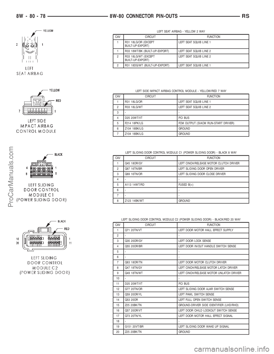
LEFT SEAT AIRBAG - YELLOW 2 WAY
CAV CIRCUIT FUNCTION
1 R31 18LG/OR (EXCEPT
BUILT-UP-EXPORT)LEFT SEAT SQUIB LINE 1
1 R33 18WT/BK (BUILT-UP-EXPORT) LEFT SEAT SQUIB LINE 2
2 R33 18LG/WT (EXCEPT
BUILT-UP-EXPORT)LEFT SEAT SQUIB LINE 2
2 R31 18DG/WT (BUILT-UP-EXPORT) LEFT SEAT SQUIB LINE 1
LEFT SIDE IMPACT AIRBAG CONTROL MODULE - YELLOW/RED 7 WAY
CAV CIRCUIT FUNCTION
1 R31 18LG/OR LEFT SEAT SQUIB LINE 1
2 R33 18LG/WT LEFT SEAT SQUIB LINE 2
3- -
4 D25 20WT/VT PCI BUS
5 F214 18PK/LG FCM OUTPUT (SIACM RUN-START DRIVER)
6 Z104 18BK/LG GROUND
7 Z104 18BK/LG GROUND
LEFT SLIDING DOOR CONTROL MODULE C1 (POWER SLIDING DOOR) - BLACK 8 WAY
CAV CIRCUIT FUNCTION
1 Q45 18OR/GY LEFT CINCH/RELEASE MOTOR CLUTCH DRIVER
2 Q67 16TN/BR LEFT SLIDING DOOR OPEN DRIVER
3 Q69 16TN/OR LEFT SLIDING DOOR CLOSE DRIVER
4- -
5 A113 14WT/RD FUSED B(+)
6- -
7- -
8 Z123 14BK/WT GROUND
LEFT SLIDING DOOR CONTROL MODULE C2 (POWER SLIDING DOOR) - BLACK/RED 20 WAY
CAV CIRCUIT FUNCTION
1 Q71 20TN/VT LEFT DOOR MOTOR HALL EFFECT SUPPLY
2- -
3 Q35 20OR/GY LEFT DOOR LOCK SENSE
4 Q55 20OR/BR LEFT DOOR IN/OUT HANDLE SWITCH SENSE
5- -
6- -
7 Q63 18OR/TN LEFT DOOR MOTOR CLUTCH DRIVER
8 Q47 18TN/GY LEFT CINCH/RELEASE MOTOR LATCH DRIVER
9 Q49 18TN/WT LEFT CINCH/RELEASE MOTOR UNLATCH DRIVER
10 - -
11 D25 20WT/VT PCI BUS
12 G77 20TN/OR LEFT SLIDING DOOR AJAR SWITCH SENSE
13 Q59 20OR/YL LEFT PAWL SWITCH SENSE
14 Q53 20OR LEFT FULL OPEN SWITCH SENSE
15 Z25 20BK/TN GROUND-DRIVER SIDE IDENTIFIER (LHD/RHD)
16 Q57 20OR/VT LEFT DOOR CHILD LOCKOUT SWITCH SENSE
17 Q73 20TN/YL LEFT DOOR MOTOR HALL EFFECT SIGNAL
18 - -
19 G151 20VT/BR LEFT SLIDING DOOR WAKE UP SIGNAL
20 Z25 20BK/TN GROUND
8W - 80 - 78 8W-80 CONNECTOR PIN-OUTSRS
ProCarManuals.com
Page 1994 of 2399
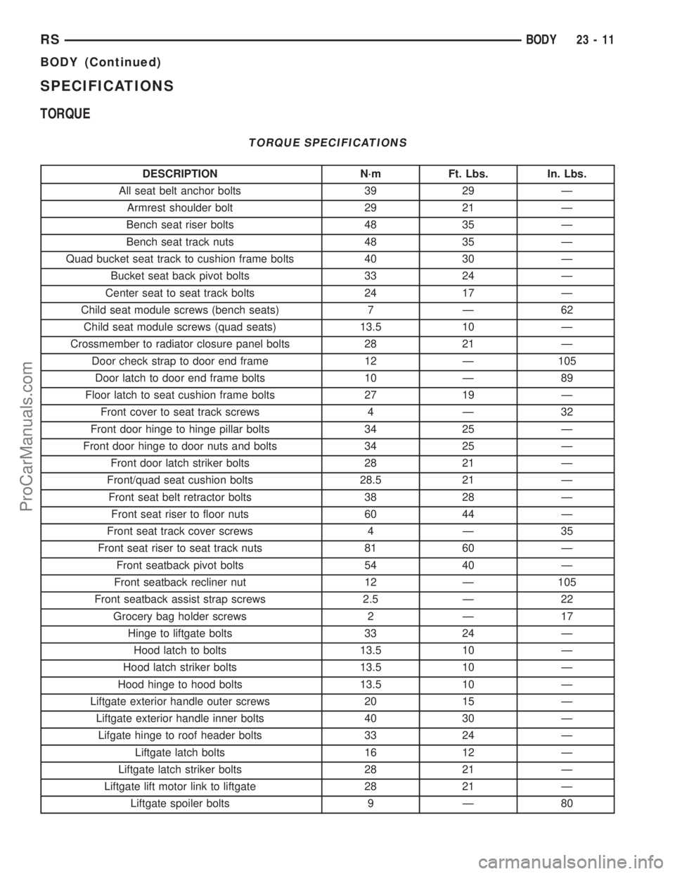
SPECIFICATIONS
TORQUE
TORQUE SPECIFICATIONS
DESCRIPTION N´m Ft. Lbs. In. Lbs.
All seat belt anchor bolts 39 29 Ð
Armrest shoulder bolt 29 21 Ð
Bench seat riser bolts 48 35 Ð
Bench seat track nuts 48 35 Ð
Quad bucket seat track to cushion frame bolts 40 30 Ð
Bucket seat back pivot bolts 33 24 Ð
Center seat to seat track bolts 24 17 Ð
Child seat module screws (bench seats) 7 Ð 62
Child seat module screws (quad seats) 13.5 10 Ð
Crossmember to radiator closure panel bolts 28 21 Ð
Door check strap to door end frame 12 Ð 105
Door latch to door end frame bolts 10 Ð 89
Floor latch to seat cushion frame bolts 27 19 Ð
Front cover to seat track screws 4 Ð 32
Front door hinge to hinge pillar bolts 34 25 Ð
Front door hinge to door nuts and bolts 34 25 Ð
Front door latch striker bolts 28 21 Ð
Front/quad seat cushion bolts 28.5 21 Ð
Front seat belt retractor bolts 38 28 Ð
Front seat riser to floor nuts 60 44 Ð
Front seat track cover screws 4 Ð 35
Front seat riser to seat track nuts 81 60 Ð
Front seatback pivot bolts 54 40 Ð
Front seatback recliner nut 12 Ð 105
Front seatback assist strap screws 2.5 Ð 22
Grocery bag holder screws 2 Ð 17
Hinge to liftgate bolts 33 24 Ð
Hood latch to bolts 13.5 10 Ð
Hood latch striker bolts 13.5 10 Ð
Hood hinge to hood bolts 13.5 10 Ð
Liftgate exterior handle outer screws 20 15 Ð
Liftgate exterior handle inner bolts 40 30 Ð
Lifgate hinge to roof header bolts 33 24 Ð
Liftgate latch bolts 16 12 Ð
Liftgate latch striker bolts 28 21 Ð
Liftgate lift motor link to liftgate 28 21 Ð
Liftgate spoiler bolts 9 Ð 80
RSBODY23-11
BODY (Continued)
ProCarManuals.com
Page 2068 of 2399
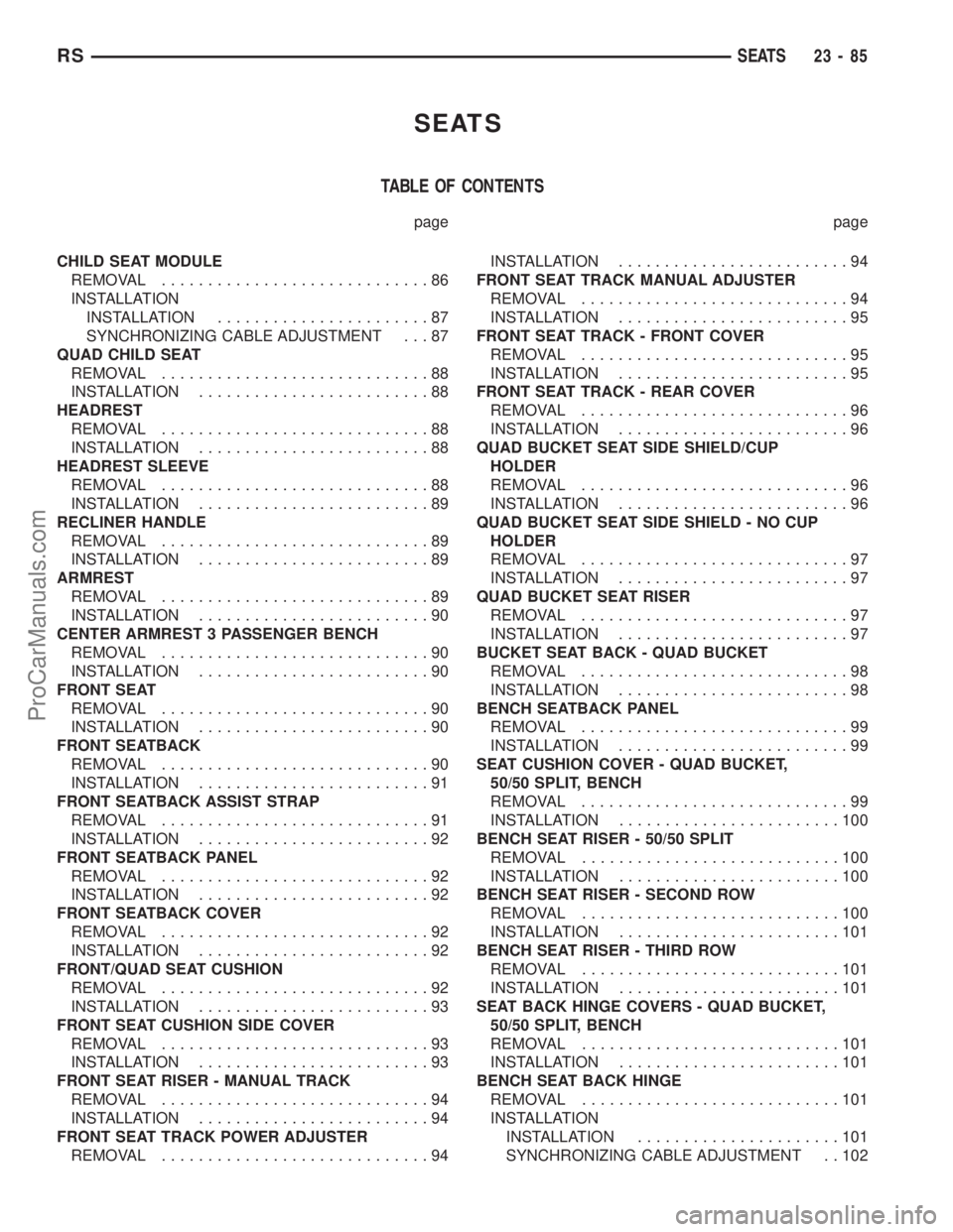
SEATS
TABLE OF CONTENTS
page page
CHILD SEAT MODULE
REMOVAL.............................86
INSTALLATION
INSTALLATION.......................87
SYNCHRONIZING CABLE ADJUSTMENT . . . 87
QUAD CHILD SEAT
REMOVAL.............................88
INSTALLATION.........................88
HEADREST
REMOVAL.............................88
INSTALLATION.........................88
HEADREST SLEEVE
REMOVAL.............................88
INSTALLATION.........................89
RECLINER HANDLE
REMOVAL.............................89
INSTALLATION.........................89
ARMREST
REMOVAL.............................89
INSTALLATION.........................90
CENTER ARMREST 3 PASSENGER BENCH
REMOVAL.............................90
INSTALLATION.........................90
FRONT SEAT
REMOVAL.............................90
INSTALLATION.........................90
FRONT SEATBACK
REMOVAL.............................90
INSTALLATION.........................91
FRONT SEATBACK ASSIST STRAP
REMOVAL.............................91
INSTALLATION.........................92
FRONT SEATBACK PANEL
REMOVAL.............................92
INSTALLATION.........................92
FRONT SEATBACK COVER
REMOVAL.............................92
INSTALLATION.........................92
FRONT/QUAD SEAT CUSHION
REMOVAL.............................92
INSTALLATION.........................93
FRONT SEAT CUSHION SIDE COVER
REMOVAL.............................93
INSTALLATION.........................93
FRONT SEAT RISER - MANUAL TRACK
REMOVAL.............................94
INSTALLATION.........................94
FRONT SEAT TRACK POWER ADJUSTER
REMOVAL.............................94INSTALLATION.........................94
FRONT SEAT TRACK MANUAL ADJUSTER
REMOVAL.............................94
INSTALLATION.........................95
FRONT SEAT TRACK - FRONT COVER
REMOVAL.............................95
INSTALLATION.........................95
FRONT SEAT TRACK - REAR COVER
REMOVAL.............................96
INSTALLATION.........................96
QUAD BUCKET SEAT SIDE SHIELD/CUP
HOLDER
REMOVAL.............................96
INSTALLATION.........................96
QUAD BUCKET SEAT SIDE SHIELD - NO CUP
HOLDER
REMOVAL.............................97
INSTALLATION.........................97
QUAD BUCKET SEAT RISER
REMOVAL.............................97
INSTALLATION.........................97
BUCKET SEAT BACK - QUAD BUCKET
REMOVAL.............................98
INSTALLATION.........................98
BENCH SEATBACK PANEL
REMOVAL.............................99
INSTALLATION.........................99
SEAT CUSHION COVER - QUAD BUCKET,
50/50 SPLIT, BENCH
REMOVAL.............................99
INSTALLATION........................100
BENCH SEAT RISER - 50/50 SPLIT
REMOVAL............................100
INSTALLATION........................100
BENCH SEAT RISER - SECOND ROW
REMOVAL............................100
INSTALLATION........................101
BENCH SEAT RISER - THIRD ROW
REMOVAL............................101
INSTALLATION........................101
SEAT BACK HINGE COVERS - QUAD BUCKET,
50/50 SPLIT, BENCH
REMOVAL............................101
INSTALLATION........................101
BENCH SEAT BACK HINGE
REMOVAL............................101
INSTALLATION
INSTALLATION......................101
SYNCHRONIZING CABLE ADJUSTMENT . . 102
RSSEATS23-85
ProCarManuals.com
Page 2069 of 2399
BENCH SEAT BACK
REMOVAL............................102
INSTALLATION........................103
BENCH SEAT BACK COVER
REMOVAL............................103
INSTALLATION........................103
BENCH SEAT TRACK
REMOVAL............................103
INSTALLATION........................104
PLASTIC GROCERY BAG RETAINER
REMOVAL............................104
INSTALLATION........................104UNDER SEAT STORAGE BIN
REMOVAL............................104
INSTALLATION........................105
UNDER SEAT STORAGE BIN GUIDE
REMOVAL............................105
INSTALLATION........................105
UNDER SEAT STORAGE BIN LOCK/LATCH
REMOVAL............................105
INSTALLATION........................105
LUMBAR SUPPORT
REMOVAL............................106
INSTALLATION........................106
CHILD SEAT MODULE
REMOVAL
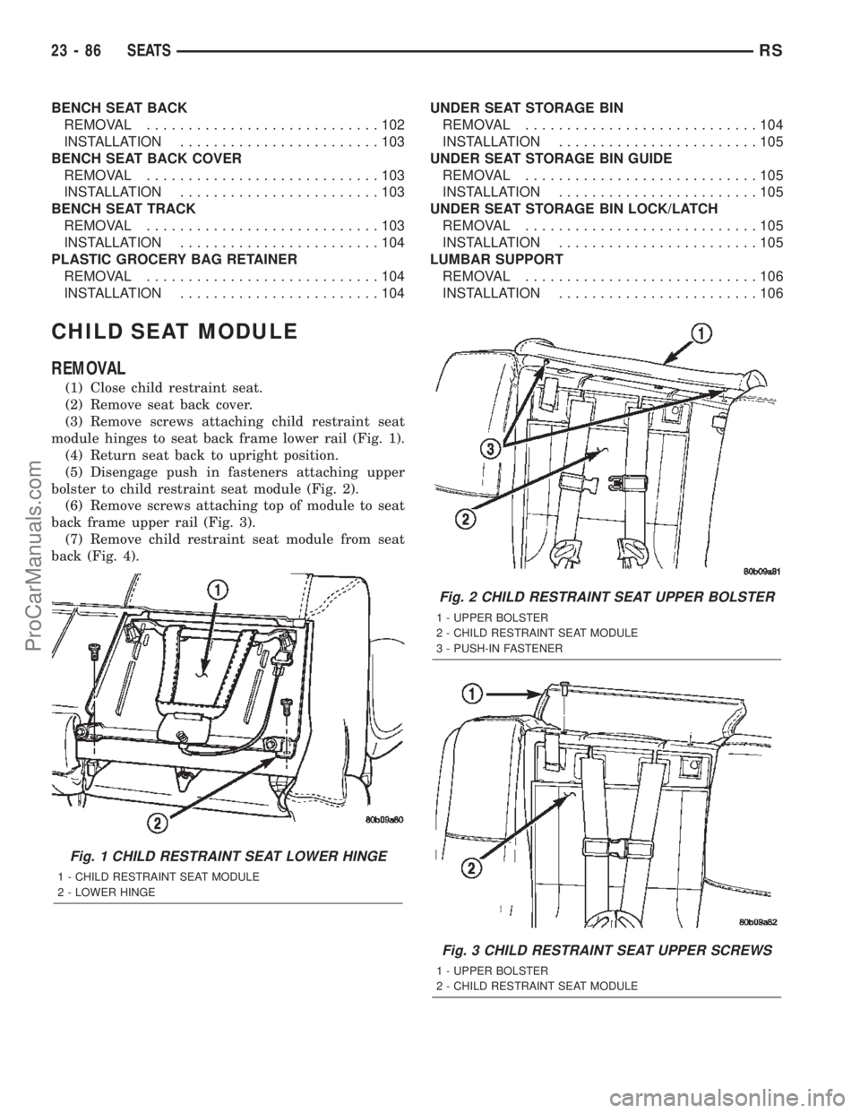
(1) Close child restraint seat.
(2) Remove seat back cover.
(3) Remove screws attaching child restraint seat
module hinges to seat back frame lower rail (Fig. 1).
(4) Return seat back to upright position.
(5) Disengage push in fasteners attaching upper
bolster to child restraint seat module (Fig. 2).
(6) Remove screws attaching top of module to seat
back frame upper rail (Fig. 3).
(7) Remove child restraint seat module from seat
back (Fig. 4).
Fig. 1 CHILD RESTRAINT SEAT LOWER HINGE
1 - CHILD RESTRAINT SEAT MODULE
2 - LOWER HINGE
Fig. 2 CHILD RESTRAINT SEAT UPPER BOLSTER
1 - UPPER BOLSTER
2 - CHILD RESTRAINT SEAT MODULE
3 - PUSH-IN FASTENER
Fig. 3 CHILD RESTRAINT SEAT UPPER SCREWS
1 - UPPER BOLSTER
2 - CHILD RESTRAINT SEAT MODULE
23 - 86 SEATSRS
ProCarManuals.com
Page 2070 of 2399
INSTALLATION
INSTALLATION
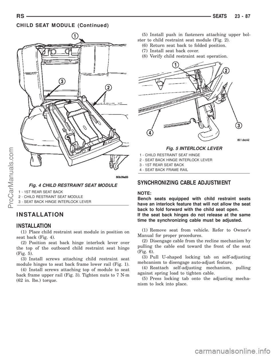
(1) Place child restraint seat module in position on
seat back (Fig. 4).
(2) Position seat back hinge interlock lever over
the top of the outboard child restraint seat hinge
(Fig. 5).
(3) Install screws attaching child restraint seat
module hinges to seat back frame lower rail (Fig. 1).
(4) Install screws attaching top of module to seat
back frame upper rail (Fig. 3). Tighten nuts to 7 N´m
(62 in. lbs.) torque.(5) Install push in fasteners attaching upper bol-
ster to child restraint seat module (Fig. 2).
(6) Return seat back to folded position.
(7) Install seat back cover.
(8) Verify child restraint seat operation.
SYNCHRONIZING CABLE ADJUSTMENT
NOTE:
Bench seats equipped with child restraint seats
have an interlock feature that will not allow the seat
back to fold forward with the child seat open.
If the seat back hinges do not release at the same
time the synchronizing cable must be adjusted.
(1) Remove seat from vehicle. Refer to Owner's
Manual for proper procedures.
(2) Disengage cable from the recline mechanism by
pulling the cable end toward the front of the seat
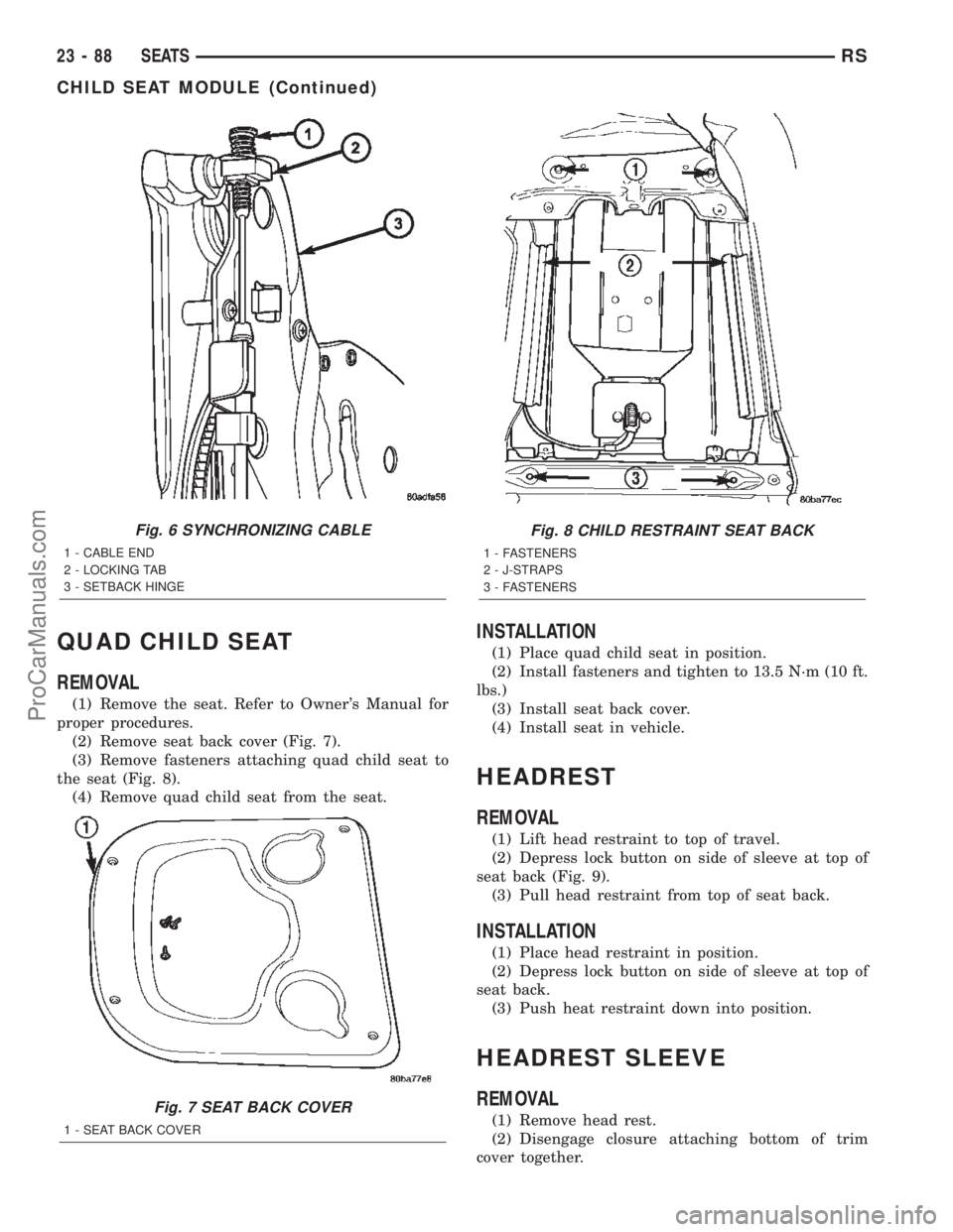
(Fig. 6).
(3) Pull U-shaped locking tab on self-adjusting
mehcanism to disengage auto-adjust feature.
(4) Reattach self-adjusting mechanism, pulling
against spring load to tighten cable.
(5) Press locking tab onto the adjusting mecha-
nism to lock into place.
Fig. 4 CHILD RESTRAINT SEAT MODULE
1 - 1ST REAR SEAT BACK
2 - CHILD RESTRAINT SEAT MODULE
3 - SEAT BACK HINGE INTERLOCK LEVER
Fig. 5 INTERLOCK LEVER
1 - CHILD RESTRAINT SEAT HINGE
2 - SEAT BACK HINGE INTERLOCK LEVER
3 - 1ST REAR SEAT BACK
4 - SEAT BACK FRAME RAIL
RSSEATS23-87
CHILD SEAT MODULE (Continued)
ProCarManuals.com
Page 2071 of 2399
QUAD CHILD SEAT
REMOVAL
(1) Remove the seat. Refer to Owner's Manual for
proper procedures.
(2) Remove seat back cover (Fig. 7).
(3) Remove fasteners attaching quad child seat to
the seat (Fig. 8).
(4) Remove quad child seat from the seat.
INSTALLATION
(1) Place quad child seat in position.
(2) Install fasteners and tighten to 13.5 N´m (10 ft.
lbs.)
(3) Install seat back cover.
(4) Install seat in vehicle.
HEADREST
REMOVAL
(1) Lift head restraint to top of travel.
(2) Depress lock button on side of sleeve at top of
seat back (Fig. 9).
(3) Pull head restraint from top of seat back.
INSTALLATION
(1) Place head restraint in position.
(2) Depress lock button on side of sleeve at top of
seat back.
(3) Push heat restraint down into position.
HEADREST SLEEVE
REMOVAL
(1) Remove head rest.
(2) Disengage closure attaching bottom of trim
cover together.
Fig. 6 SYNCHRONIZING CABLE
1 - CABLE END
2 - LOCKING TAB
3 - SETBACK HINGE
Fig. 7 SEAT BACK COVER
1 - SEAT BACK COVER
Fig. 8 CHILD RESTRAINT SEAT BACK
1 - FASTENERS
2 - J-STRAPS
3 - FASTENERS
23 - 88 SEATSRS
CHILD SEAT MODULE (Continued)
ProCarManuals.com
Page 2081 of 2399
(3) Install the seat side shield/cup holder. (Refer to
23 - BODY/SEATS/QUAD BUCKET SEAT SIDE
SHIELD/CUP HOLDER - INSTALLATION)
(4) Install the seat. Refer to Owner's Manual for
proper procedures.
BUCKET SEAT BACK - QUAD
BUCKET
REMOVAL
NOTE: Quad seats equipped with child restraint
seats have an interlock feature that will not allow
the seat back to fold forward with the child seat
open.
(1) Remove the headrests. (Refer to 23 - BODY/
SEATS/HEADREST - REMOVAL)
(2) Remove the armrests, if equipped. (Refer to 23
- BODY/SEATS/ARMREST - REMOVAL)
(3) Remove the seatback hinge covers. (Refer to 23
- BODY/SEATS/SEAT BACK HINGE COVERS -
QUAD BUCKET, 50/50 SPLIT, BENCH - REMOVAL)
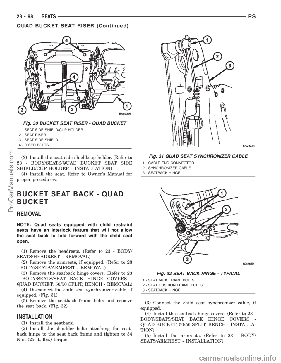
(4) Disconnect the child seat synchronizer cable, if
equipped. (Fig. 31)
(5) Remove the seatback frame bolts and remove
the seat back. (Fig. 32)
INSTALLATION
(1) Install the seatback.
(2) Install the shoulder bolts attaching the seat-
back hinge to the seat back frame and tighten to 34
N´m (25 ft. lbs.) torque.(3) Connect the child seat synchronizer cable, if
equipped.
(4) Install the seatback hinge covers. (Refer to 23 -
BODY/SEATS/SEAT BACK HINGE COVERS -
QUAD BUCKET, 50/50 SPLIT, BENCH - INSTALLA-
TION)
(5) Install the armrests. (Refer to 23 - BODY/
SEATS/ARMREST - INSTALLATION)
Fig. 30 BUCKET SEAT RISER - QUAD BUCKET
1 - SEAT SIDE SHIELD/CUP HOLDER
2 - SEAT RISER
3 - SEAT SIDE SHIELD
4 - RISER BOLTS
Fig. 31 QUAD SEAT SYNCHRONIZER CABLE
1 - CABLE END CONNECTOR
2 - SYNCHRONIZER CABLE
3 - SEATBACK HINGE
Fig. 32 SEAT BACK HINGE - TYPICAL
1 - SEATBACK FRAME BOLTS
2 - SEAT CUSHION FRAME BOLTS
3 - SEATBACK HINGE
23 - 98 SEATSRS
QUAD BUCKET SEAT RISER (Continued)
ProCarManuals.com
Page 2082 of 2399
(6) Install the headreast. (Refer to 23 - BODY/
SEATS/HEADREST - INSTALLATION)
(7) Verify seatback operation.
BENCH SEATBACK PANEL
REMOVAL
(1) On third row seats remove plastic grocery bag
retainer. (Refer to 23 - BODY/SEATS/PLASTIC GRO-
CERY BAG RETAINER - REMOVAL)
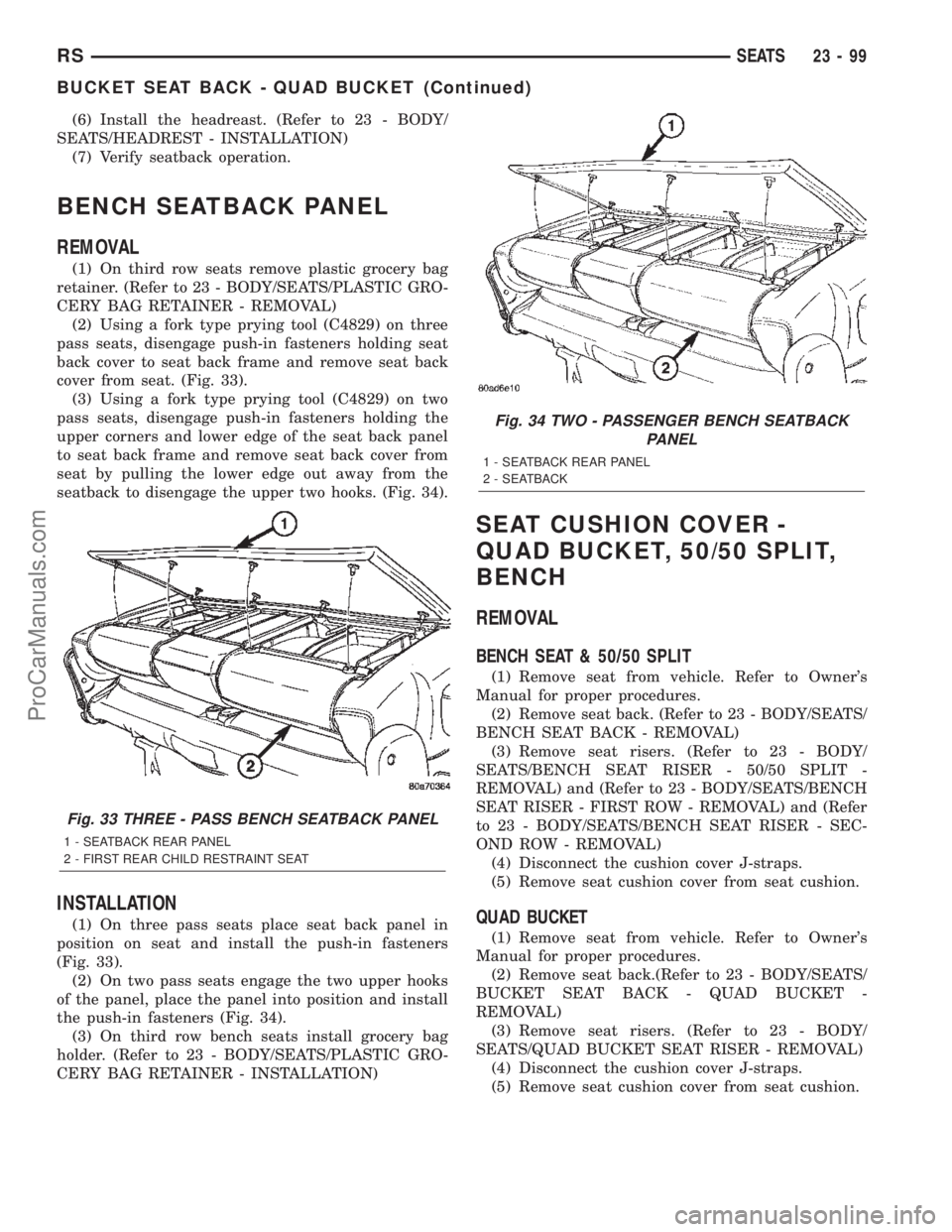
(2) Using a fork type prying tool (C4829) on three
pass seats, disengage push-in fasteners holding seat
back cover to seat back frame and remove seat back
cover from seat. (Fig. 33).
(3) Using a fork type prying tool (C4829) on two
pass seats, disengage push-in fasteners holding the
upper corners and lower edge of the seat back panel
to seat back frame and remove seat back cover from
seat by pulling the lower edge out away from the
seatback to disengage the upper two hooks. (Fig. 34).
INSTALLATION
(1) On three pass seats place seat back panel in
position on seat and install the push-in fasteners
(Fig. 33).
(2) On two pass seats engage the two upper hooks
of the panel, place the panel into position and install
the push-in fasteners (Fig. 34).
(3) On third row bench seats install grocery bag
holder. (Refer to 23 - BODY/SEATS/PLASTIC GRO-
CERY BAG RETAINER - INSTALLATION)
SEAT CUSHION COVER -
QUAD BUCKET, 50/50 SPLIT,
BENCH
REMOVAL
BENCH SEAT & 50/50 SPLIT
(1) Remove seat from vehicle. Refer to Owner's
Manual for proper procedures.
(2) Remove seat back. (Refer to 23 - BODY/SEATS/
BENCH SEAT BACK - REMOVAL)
(3) Remove seat risers. (Refer to 23 - BODY/
SEATS/BENCH SEAT RISER - 50/50 SPLIT -
REMOVAL) and (Refer to 23 - BODY/SEATS/BENCH
SEAT RISER - FIRST ROW - REMOVAL) and (Refer
to 23 - BODY/SEATS/BENCH SEAT RISER - SEC-
OND ROW - REMOVAL)
(4) Disconnect the cushion cover J-straps.
(5) Remove seat cushion cover from seat cushion.
QUAD BUCKET
(1) Remove seat from vehicle. Refer to Owner's
Manual for proper procedures.
(2) Remove seat back.(Refer to 23 - BODY/SEATS/
BUCKET SEAT BACK - QUAD BUCKET -
REMOVAL)
(3) Remove seat risers. (Refer to 23 - BODY/
SEATS/QUAD BUCKET SEAT RISER - REMOVAL)
(4) Disconnect the cushion cover J-straps.
(5) Remove seat cushion cover from seat cushion.
Fig. 33 THREE - PASS BENCH SEATBACK PANEL
1 - SEATBACK REAR PANEL
2 - FIRST REAR CHILD RESTRAINT SEAT
Fig. 34 TWO - PASSENGER BENCH SEATBACK
PANEL
1 - SEATBACK REAR PANEL
2 - SEATBACK
RSSEATS23-99
BUCKET SEAT BACK - QUAD BUCKET (Continued)
ProCarManuals.com
Page 2084 of 2399
INSTALLATION
(1) Place riser in position on seat.
(2) Install bolts attaching seat riser to seat cush-
ion frame (Fig. 36). Tighten bolts to 48 N´m (35 ft.
lbs.) torque.
(3) Install seat into vehicle.
BENCH SEAT RISER - THIRD
ROW
REMOVAL
(1) Remove seat track. (Refer to 23 - BODY/
SEATS/BENCH SEAT TRACK - REMOVAL)
(2) Remove bolts attaching riser to seat cushion
frame and remove the riser. (Fig. 41).
INSTALLATION
(1) Place riser in position on seat.
(2) Install bolts attaching riser to seat cushion
frame (Fig. 41). Tighten nuts to 48 N´m (35 ft. lbs.)
torque.
(3) Install seat track. (Refer to 23 - BODY/SEATS/
BENCH SEAT TRACK - INSTALLATION)
SEAT BACK HINGE COVERS -
QUAD BUCKET, 50/50 SPLIT,
BENCH
REMOVAL
(1) Remove seat from vehicle. Refer to Owner's
Manual for proper procedures.
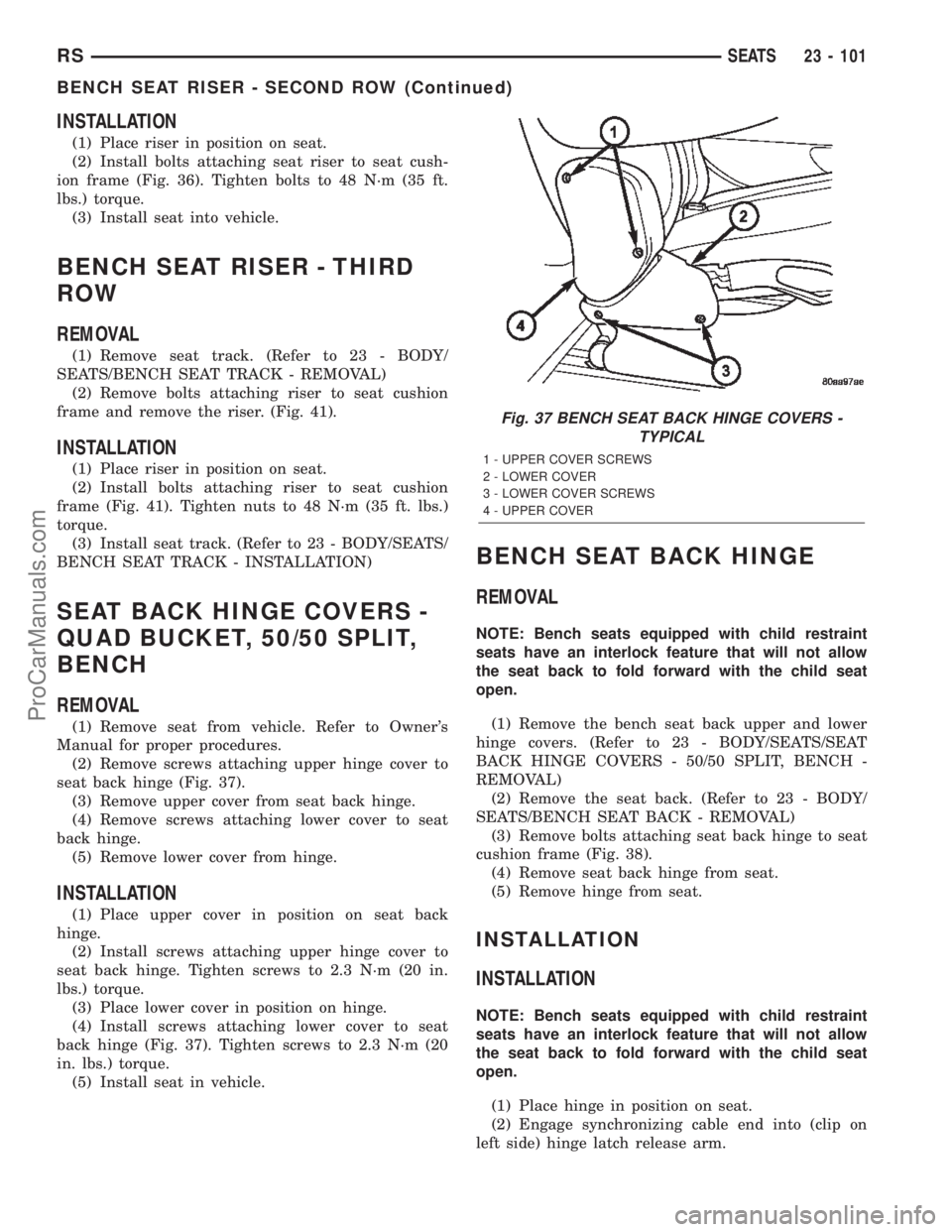
(2) Remove screws attaching upper hinge cover to
seat back hinge (Fig. 37).
(3) Remove upper cover from seat back hinge.
(4) Remove screws attaching lower cover to seat
back hinge.
(5) Remove lower cover from hinge.
INSTALLATION
(1) Place upper cover in position on seat back
hinge.
(2) Install screws attaching upper hinge cover to
seat back hinge. Tighten screws to 2.3 N´m (20 in.
lbs.) torque.
(3) Place lower cover in position on hinge.
(4) Install screws attaching lower cover to seat
back hinge (Fig. 37). Tighten screws to 2.3 N´m (20
in. lbs.) torque.
(5) Install seat in vehicle.
BENCH SEAT BACK HINGE
REMOVAL
NOTE: Bench seats equipped with child restraint
seats have an interlock feature that will not allow
the seat back to fold forward with the child seat
open.
(1) Remove the bench seat back upper and lower
hinge covers. (Refer to 23 - BODY/SEATS/SEAT
BACK HINGE COVERS - 50/50 SPLIT, BENCH -
REMOVAL)
(2) Remove the seat back. (Refer to 23 - BODY/
SEATS/BENCH SEAT BACK - REMOVAL)
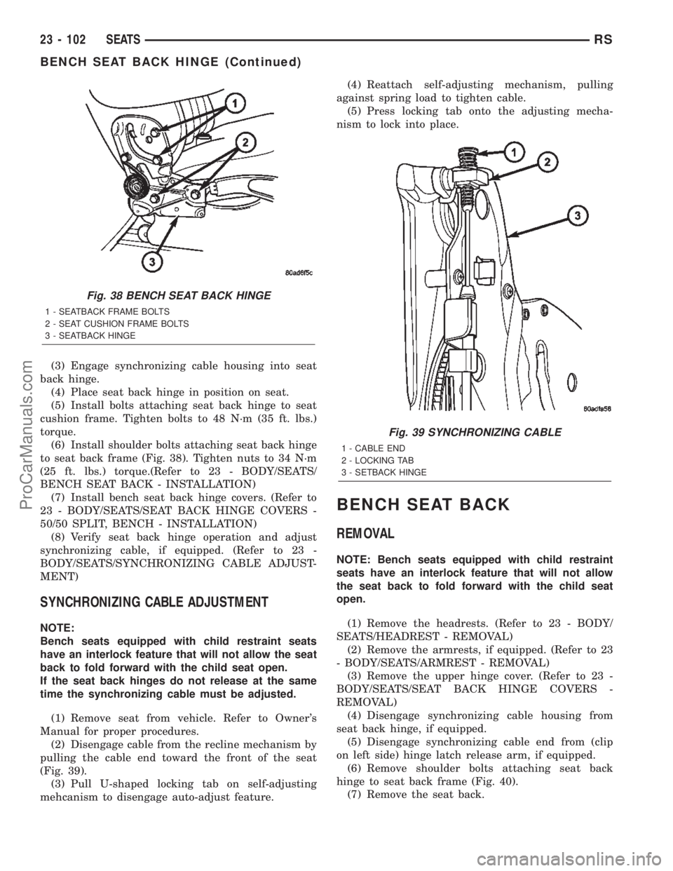
(3) Remove bolts attaching seat back hinge to seat
cushion frame (Fig. 38).
(4) Remove seat back hinge from seat.
(5) Remove hinge from seat.
INSTALLATION
INSTALLATION
NOTE: Bench seats equipped with child restraint
seats have an interlock feature that will not allow
the seat back to fold forward with the child seat
open.
(1) Place hinge in position on seat.
(2) Engage synchronizing cable end into (clip on
left side) hinge latch release arm.
Fig. 37 BENCH SEAT BACK HINGE COVERS -
TYPICAL
1 - UPPER COVER SCREWS
2 - LOWER COVER
3 - LOWER COVER SCREWS
4 - UPPER COVER
RSSEATS23 - 101
BENCH SEAT RISER - SECOND ROW (Continued)
ProCarManuals.com
Page 2085 of 2399
(3) Engage synchronizing cable housing into seat
back hinge.
(4) Place seat back hinge in position on seat.
(5) Install bolts attaching seat back hinge to seat
cushion frame. Tighten bolts to 48 N´m (35 ft. lbs.)
torque.
(6) Install shoulder bolts attaching seat back hinge
to seat back frame (Fig. 38). Tighten nuts to 34 N´m
(25 ft. lbs.) torque.(Refer to 23 - BODY/SEATS/
BENCH SEAT BACK - INSTALLATION)
(7) Install bench seat back hinge covers. (Refer to
23 - BODY/SEATS/SEAT BACK HINGE COVERS -
50/50 SPLIT, BENCH - INSTALLATION)
(8) Verify seat back hinge operation and adjust
synchronizing cable, if equipped. (Refer to 23 -
BODY/SEATS/SYNCHRONIZING CABLE ADJUST-
MENT)
SYNCHRONIZING CABLE ADJUSTMENT
NOTE:
Bench seats equipped with child restraint seats
have an interlock feature that will not allow the seat
back to fold forward with the child seat open.
If the seat back hinges do not release at the same
time the synchronizing cable must be adjusted.
(1) Remove seat from vehicle. Refer to Owner's
Manual for proper procedures.
(2) Disengage cable from the recline mechanism by
pulling the cable end toward the front of the seat
(Fig. 39).
(3) Pull U-shaped locking tab on self-adjusting
mehcanism to disengage auto-adjust feature.(4) Reattach self-adjusting mechanism, pulling
against spring load to tighten cable.
(5) Press locking tab onto the adjusting mecha-
nism to lock into place.
BENCH SEAT BACK
REMOVAL
NOTE: Bench seats equipped with child restraint
seats have an interlock feature that will not allow
the seat back to fold forward with the child seat
open.
(1) Remove the headrests. (Refer to 23 - BODY/
SEATS/HEADREST - REMOVAL)
(2) Remove the armrests, if equipped. (Refer to 23
- BODY/SEATS/ARMREST - REMOVAL)
(3) Remove the upper hinge cover. (Refer to 23 -
BODY/SEATS/SEAT BACK HINGE COVERS -
REMOVAL)
(4) Disengage synchronizing cable housing from
seat back hinge, if equipped.
(5) Disengage synchronizing cable end from (clip
on left side) hinge latch release arm, if equipped.
(6) Remove shoulder bolts attaching seat back
hinge to seat back frame (Fig. 40).
(7) Remove the seat back.
Fig. 38 BENCH SEAT BACK HINGE
1 - SEATBACK FRAME BOLTS
2 - SEAT CUSHION FRAME BOLTS
3 - SEATBACK HINGE
Fig. 39 SYNCHRONIZING CABLE
1 - CABLE END
2 - LOCKING TAB
3 - SETBACK HINGE
23 - 102 SEATSRS
BENCH SEAT BACK HINGE (Continued)
ProCarManuals.com