heating & air conditioning CHRYSLER TOWN AND COUNTRY 2002 Service Manual
[x] Cancel search | Manufacturer: CHRYSLER, Model Year: 2002, Model line: TOWN AND COUNTRY, Model: CHRYSLER TOWN AND COUNTRY 2002Pages: 2399, PDF Size: 57.96 MB
Page 1 of 2399
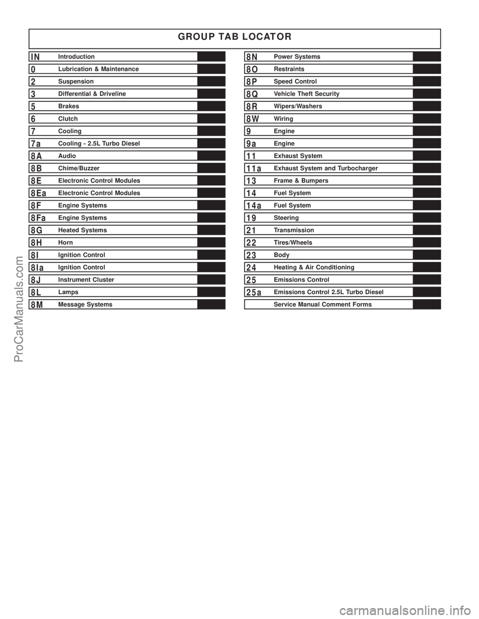
GROUP TAB LOCATOR
INIntroduction
0Lubrication & Maintenance
2Suspension
3Differential & Driveline
5Brakes
6Clutch
7Cooling
7aCooling - 2.5L Turbo Diesel
8AAudio
8BChime/Buzzer
8EElectronic Control Modules
8EaElectronic Control Modules
8FEngine Systems
8FaEngine Systems
8GHeated Systems
8HHorn
8IIgnition Control
8IaIgnition Control
8JInstrument Cluster
8LLamps
8MMessage Systems
8NPower Systems
8ORestraints
8PSpeed Control
8QVehicle Theft Security
8RWipers/Washers
8WWiring
9Engine
9aEngine
11Exhaust System
11aExhaust System and Turbocharger
13Frame & Bumpers
14Fuel System
14aFuel System
19Steering
21Transmission
22Tires/Wheels
23Body
24Heating & Air Conditioning
25Emissions Control
25aEmissions Control 2.5L Turbo Diesel
Service Manual Comment Forms
ProCarManuals.com
Page 176 of 2399
(27) Install lower steering column cover/knee
blocker (Fig. 62).
(28) Install silencer panel below lower steering col-
umn cover/knee blocker.
NOTE: When reconnecting the battery on a vehicle
that has had the airbag module removed, the fol-
lowing procedure should be used.
(29) Reconnect ground cable to negative post of
battery in following manor:
(a) Connect scan tool (DRBIIIt) to data link
diagnostic connector located below steering column.
(b) Turn ignition key to ON position. Exit vehi-
cle with scan tool leaving scan tool harness
plugged in.
(c) Ensuring that there are no occupants in vehi-
cle, connect ground (-) cable to the negative post of
the battery.
(d) Using scan tool, read and record any airbag
fault codes. Refer to Appropriate Diagnostic Infor-
mation if any faults are found.
(e) Through drivers open window, Reach around
back of steering wheel (between steering wheel and
instrument cluster) and turn ignition key to OFF,
then back ON while observing instrument cluster
airbag indicator lamp. It should go on for six to
eight seconds, then go out. This action indicates
that airbag system is functioning normally. If air-
bag indicator lamp fails to light, blinks on and off,
or goes on and stays on, there is an airbag system
malfunction. Refer to Appropriate Diagnostic Infor-
mation to diagnose the system malfunction.
(30) Using scan tool (DRBIIIt), check for and clear
any existing adjustable pedal fault codes. The adjust-
able pedal system is now activated.
(31) Turn key to OFF and remove scan tool from
vehicle.
(32) Test operation of adjustable pedals, memory
seats (if equipped), RKE (if equipped), and all func-
tions that are steering column operated. If applica-
ble, reset the radio and the clock.
(33) Road test the vehicle to ensure proper opera-
tion of the steering and brake systems.
PEDAL TORQUE SHAFT - RHD
REMOVAL
(1) Remove the instrument panel. (Refer to 23 -
BODY/INSTRUMENT PANEL/INSTRUMENT
PANEL ASSEMBLY - REMOVAL)
(2) Remove the HVAC housing. (Refer to 24 -
HEATING & AIR CONDITIONING/DISTRIBUTION/
HVAC HOUSING - REMOVAL)
(3) Remove the retaining clip at the torque shaft
end of the brake pedal-to-torque shaft link. Removethe link from the torque shaft. Discard the retaining
clip. It is not to be reused. Replace with a new clip
when reassembled.
(4) Locate the booster input rod-to-brake pedal
torque shaft connection and remove the retaining clip
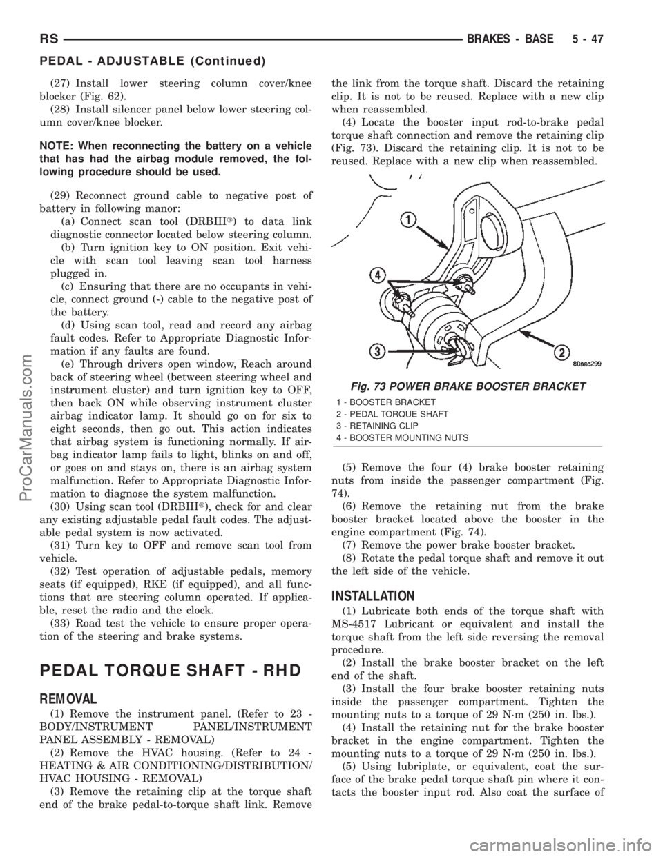
(Fig. 73). Discard the retaining clip. It is not to be
reused. Replace with a new clip when reassembled.
(5) Remove the four (4) brake booster retaining
nuts from inside the passenger compartment (Fig.
74).
(6) Remove the retaining nut from the brake
booster bracket located above the booster in the
engine compartment (Fig. 74).
(7) Remove the power brake booster bracket.
(8) Rotate the pedal torque shaft and remove it out
the left side of the vehicle.
INSTALLATION
(1) Lubricate both ends of the torque shaft with
MS-4517 Lubricant or equivalent and install the
torque shaft from the left side reversing the removal
procedure.
(2) Install the brake booster bracket on the left
end of the shaft.
(3) Install the four brake booster retaining nuts
inside the passenger compartment. Tighten the
mounting nuts to a torque of 29 N´m (250 in. lbs.).
(4) Install the retaining nut for the brake booster
bracket in the engine compartment. Tighten the
mounting nuts to a torque of 29 N´m (250 in. lbs.).
(5) Using lubriplate, or equivalent, coat the sur-
face of the brake pedal torque shaft pin where it con-
tacts the booster input rod. Also coat the surface of
Fig. 73 POWER BRAKE BOOSTER BRACKET
1 - BOOSTER BRACKET
2 - PEDAL TORQUE SHAFT
3 - RETAINING CLIP
4 - BOOSTER MOUNTING NUTS
RSBRAKES - BASE5-47
PEDAL - ADJUSTABLE (Continued)
ProCarManuals.com
Page 243 of 2399
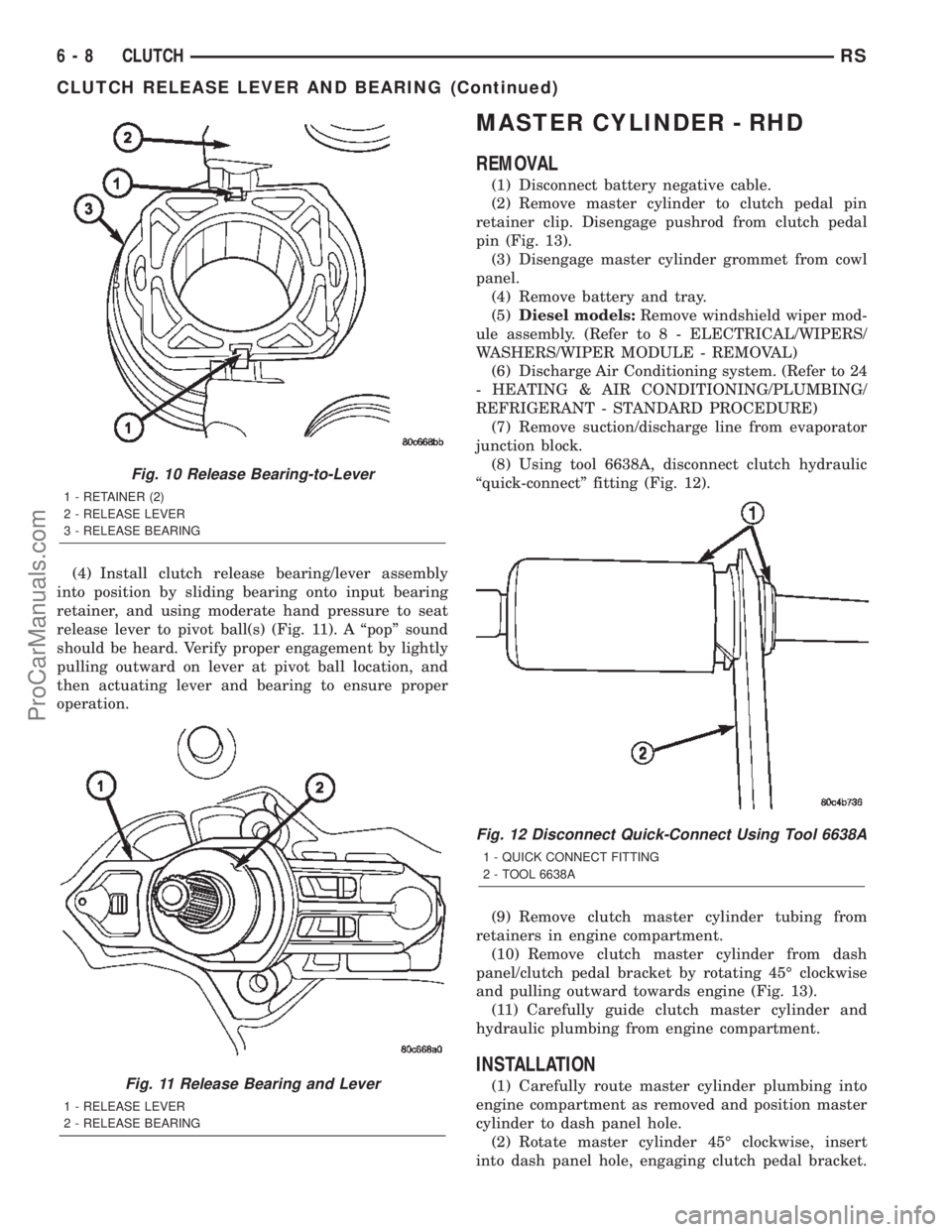
(4) Install clutch release bearing/lever assembly
into position by sliding bearing onto input bearing
retainer, and using moderate hand pressure to seat
release lever to pivot ball(s) (Fig. 11). A ªpopº sound
should be heard. Verify proper engagement by lightly
pulling outward on lever at pivot ball location, and
then actuating lever and bearing to ensure proper
operation.
MASTER CYLINDER - RHD
REMOVAL
(1) Disconnect battery negative cable.
(2) Remove master cylinder to clutch pedal pin
retainer clip. Disengage pushrod from clutch pedal
pin (Fig. 13).
(3) Disengage master cylinder grommet from cowl
panel.
(4) Remove battery and tray.
(5)Diesel models:Remove windshield wiper mod-
ule assembly. (Refer to 8 - ELECTRICAL/WIPERS/
WASHERS/WIPER MODULE - REMOVAL)
(6) Discharge Air Conditioning system. (Refer to 24
- HEATING & AIR CONDITIONING/PLUMBING/
REFRIGERANT - STANDARD PROCEDURE)
(7) Remove suction/discharge line from evaporator
junction block.
(8) Using tool 6638A, disconnect clutch hydraulic
ªquick-connectº fitting (Fig. 12).
(9) Remove clutch master cylinder tubing from
retainers in engine compartment.
(10) Remove clutch master cylinder from dash
panel/clutch pedal bracket by rotating 45É clockwise
and pulling outward towards engine (Fig. 13).
(11) Carefully guide clutch master cylinder and
hydraulic plumbing from engine compartment.
INSTALLATION
(1) Carefully route master cylinder plumbing into
engine compartment as removed and position master
cylinder to dash panel hole.
(2) Rotate master cylinder 45É clockwise, insert
into dash panel hole, engaging clutch pedal bracket.
Fig. 10 Release Bearing-to-Lever
1 - RETAINER (2)
2 - RELEASE LEVER
3 - RELEASE BEARING
Fig. 11 Release Bearing and Lever
1 - RELEASE LEVER
2 - RELEASE BEARING
Fig. 12 Disconnect Quick-Connect Using Tool 6638A
1 - QUICK CONNECT FITTING
2 - TOOL 6638A
6 - 8 CLUTCHRS
CLUTCH RELEASE LEVER AND BEARING (Continued)
ProCarManuals.com
Page 244 of 2399
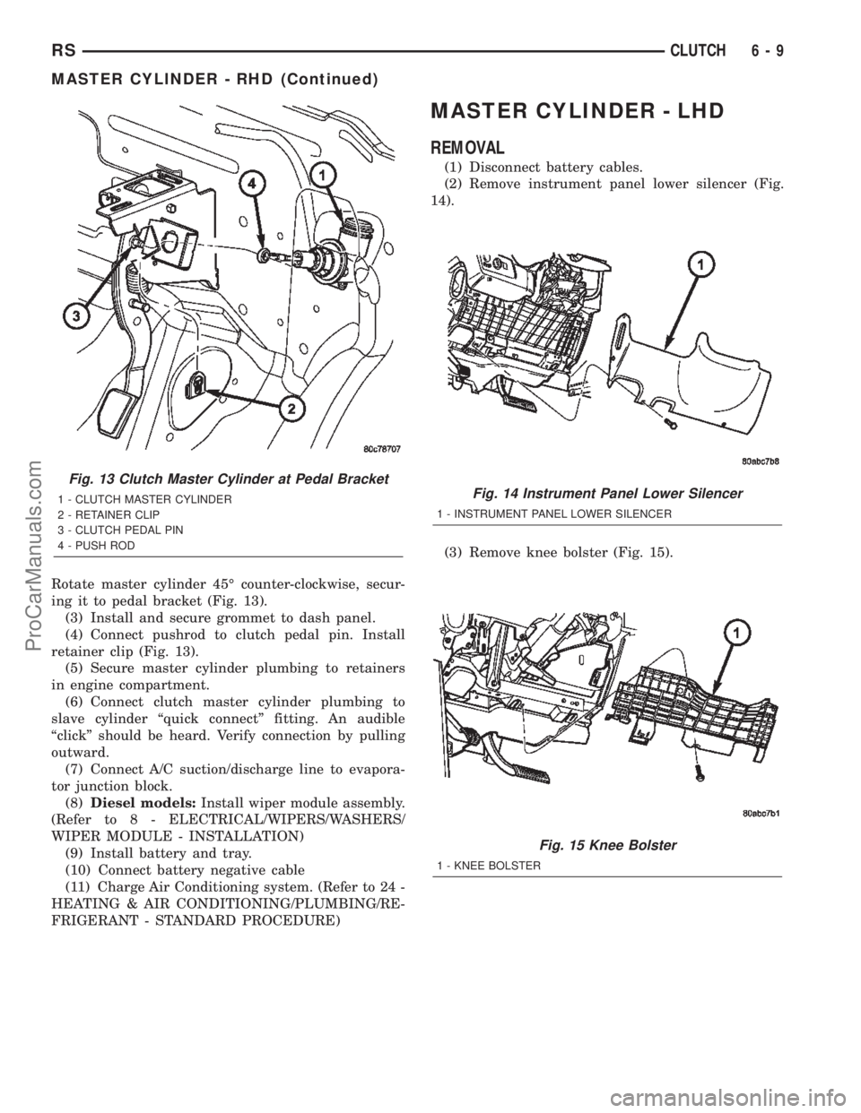
Rotate master cylinder 45É counter-clockwise, secur-
ing it to pedal bracket (Fig. 13).
(3) Install and secure grommet to dash panel.
(4) Connect pushrod to clutch pedal pin. Install
retainer clip (Fig. 13).
(5) Secure master cylinder plumbing to retainers
in engine compartment.
(6) Connect clutch master cylinder plumbing to
slave cylinder ªquick connectº fitting. An audible
ªclickº should be heard. Verify connection by pulling
outward.
(7) Connect A/C suction/discharge line to evapora-
tor junction block.
(8)Diesel models:Install wiper module assembly.
(Refer to 8 - ELECTRICAL/WIPERS/WASHERS/
WIPER MODULE - INSTALLATION)
(9) Install battery and tray.
(10) Connect battery negative cable
(11) Charge Air Conditioning system. (Refer to 24 -
HEATING & AIR CONDITIONING/PLUMBING/RE-
FRIGERANT - STANDARD PROCEDURE)
MASTER CYLINDER - LHD
REMOVAL
(1) Disconnect battery cables.
(2) Remove instrument panel lower silencer (Fig.
14).
(3) Remove knee bolster (Fig. 15).
Fig. 13 Clutch Master Cylinder at Pedal Bracket
1 - CLUTCH MASTER CYLINDER
2 - RETAINER CLIP
3 - CLUTCH PEDAL PIN
4 - PUSH RODFig. 14 Instrument Panel Lower Silencer
1 - INSTRUMENT PANEL LOWER SILENCER
Fig. 15 Knee Bolster
1 - KNEE BOLSTER
RSCLUTCH6-9
MASTER CYLINDER - RHD (Continued)
ProCarManuals.com
Page 291 of 2399

COOLING SYSTEM DIAGNOSIS-DIESEL ENGINE
CONDITION POSSIBLE CAUSES CORRECTION
TEMPERATURE GAUGE
READS LOW1. Diesel engines, due to their
inherent effiency are slower to warm
up than gasoline powered engines,
and will operate at lower
temperatures when the vehicle is
unloaded.1. The low gauge reading may
be normal. Refer to thermostats
in the manual text for
information. See Thermostat
Diagnosis-Diesel Engine.
2. Is the temperature gauge
connected to the temperature gauge
coolant sensor on the engine?2. Check, the engine
temperature sensor connector
in the engine compartment.
3. Is the temperature gauge
operating OK?3. Check gauge operation.
Repair as necessary.
4. Coolant level low in cold ambient
temperatures accompanied with poor
heater performance.4. Check coolant level in the
coolant tank. Inspect system for
leaks. Repair leaks as
necessary. Refer to the Coolant
section for WARNINGS and
precautions before removing
the pressure cap.
5. Improper operation of internal
heater doors or heater controls.5. Inspect heater and repair as
necessary. Refer to Heating
and Air Conditioning for
procedures.
TEMPERATURE GAUGE
READS HIGH. COOLANT
MAY OR MAY NOT BE
LOST OR LEAKING FROM
COOLING SYSTEM1. Trailer is being towed, a steep hill
is being climbed, vehicle is operated
in slow moving traffic, or engine is
being idled with very high ambient
(outside) temperature and the air
conditioning is on. Higher altitudes
could aggravate these conditions.1. This may be a temporary
condition and repair is not
necessary. Turn off the air
conditioning and attempt to
drive the vehicle without any of
the previous conditions.
Observe the temperature
gauge. The gauge should return
to the normal range. If the
gauge does not return to
normal range, determine the
cause for the overheating and
repair.
2. Temperature gauge reading
incorrectly.2. Check gauge. Refer to I/P
group.
3. Coolant low in coolant tank and
radiator.3. Check for coolant leaks and
repair as necessary.
4. Pressure cap not installed tightly.
If cap is loose, boiling point of
coolant will be lowered.4. Tighten cap.
5. Poor seals at pressure/vent cap. 5. (a) Check condition of cap
and cap seals. (b) Check
condition of coolant tank filler
neck. Make sure it does not
leak pressure.
7a - 2 COOLING 2.5L TURBO DIESELRG
COOLING 2.5L TURBO DIESEL (Continued)
ProCarManuals.com
Page 349 of 2399
²Ignition sense
²Intake Air Temperature Sensor
²Knock Sensor
²Leak Detection Pump Feedback
²Manifold Absolute Pressure (MAP) Sensor
²Park/Neutral (from transmission control module)
²PCI Bus
²Power Steering Pressure Switch
²Proportional Purge Sense
²SCI Receive
²Speed Control
²Throttle Position Sensor
²Torque Management Input (From TCM)
²Transaxle Control Module (TCM)
²Transaxle Gear Engagement (From TCM)
²Vehicle Speed (from transmission control mod-
ule)
NOTE: PCM Outputs:
²Air Conditioning Clutch Relay
²Automatic Shut Down (ASD) and Fuel Pump
Relays
²Data Link Connector (PCI and SCI Transmit)
²Double Start Override
²EGR Solenoid
²Fuel Injectors
²Generator Field
²High Speed Fan Relay
²Idle Air Control Motor
²Ignition Coils
²Leak Detection Pump
²Low Speed Fan Relay
²MTV Actuator
²Proportional Purge Solenoid
²SRV Valve
²Speed Control Relay
²Speed Control Vent Relay
²Speed Control Vacuum Relay
²8 Volt Output
²5 Volt Output
Based on inputs it receives, the powertrain control
module (PCM) adjusts fuel injector pulse width, idle
speed, ignition timing, and canister purge operation.
The PCM regulates the cooling fans, air conditioning
and speed control systems. The PCM changes gener-
ator charge rate by adjusting the generator field.
The PCM adjusts injector pulse width (air-fuel
ratio) based on the following inputs.
²Battery Voltage
²Intake Air Temperature Sensor
²Engine Coolant Temperature
²Engine Speed (crankshaft position sensor)²Exhaust Gas Oxygen Content (heated oxygen
sensors)
²Manifold Absolute Pressure
²Throttle Position
The PCM adjusts engine idle speed through the
idle air control motor based on the following inputs.
²Brake Switch
²Engine Coolant Temperature
²Engine Speed (crankshaft position sensor)
²Park/Neutral (transmission gear selection)
²Transaxle Gear Engagement
²Throttle Position
²Vehicle Speed (from Transmission Control Mod-
ule)
The PCM adjusts ignition timing based on the fol-
lowing inputs.
²Intake Air Temperature
²Engine Coolant Temperature
²Engine Speed (crankshaft position sensor)
²Knock Sensor
²Manifold Absolute Pressure
²Park/Neutral (transmission gear selection)
²Transaxle Gear Engagement
²Throttle Position
The automatic shut down (ASD) and fuel pump
relays are mounted externally, but turned on and off
by the powertrain control module through the same
circuit.
The camshaft and crankshaft signals are sent to
the powertrain control module. If the PCM does not
receive both signals within approximately one second
of engine cranking, it deactivates the ASD and fuel
pump relays. When these relays are deactivated,
power is shut off to the fuel injectors, ignition coils,
fuel pump and the heating element in each oxygen
sensor.
The PCM contains a voltage converter that
changes battery voltage to a regulated 8.0 volts. The
8.0 volts power the camshaft position sensor, crank-
shaft position sensor and vehicle speed sensor. The
PCM also provides a 5.0 volts supply for the engine
coolant temperature sensor, intake air temperature
sensor, manifold absolute pressure sensor and throt-
tle position sensor.
The PCM engine control strategy prevents reduced
idle speeds until after the engine operates for 320 km
(200 miles). If the PCM is replaced after 320 km (200
miles) of usage, update the mileage in new PCM. Use
the DRB scan tool to change the mileage in the PCM.
Refer to the appropriate Powertrain Diagnostic Man-
ual and the DRB scan tool.
8E - 12 ELECTRONIC CONTROL MODULESRS
POWERTRAIN CONTROL MODULE (Continued)
ProCarManuals.com
Page 1214 of 2399
NOTE: When the transaxle cooler lines are removed
from the rolled-groove type fittings at the transaxle,
damage to the inner wall of the hose will occur. To
prevent prevent potential leakage, the cooler hoses
must be cut off flush at the transaxle fitting, and a
service cooler hose splice kit must be installed
upon reassembly.
(9) Using a blade or suitable hose cutter, cut trans-
axle oil cooler lines off flush with fittings. Plug cooler
lines and fittings to prevent debris from entering
transaxle or cooler circuit. A service splice kit will be
installed upon reassembly.
(10) Disconnect transmission shift linkage and
electrical connectors.
(11) Disconnect throttle body linkage.
(12) Disconnect engine wiring harness.
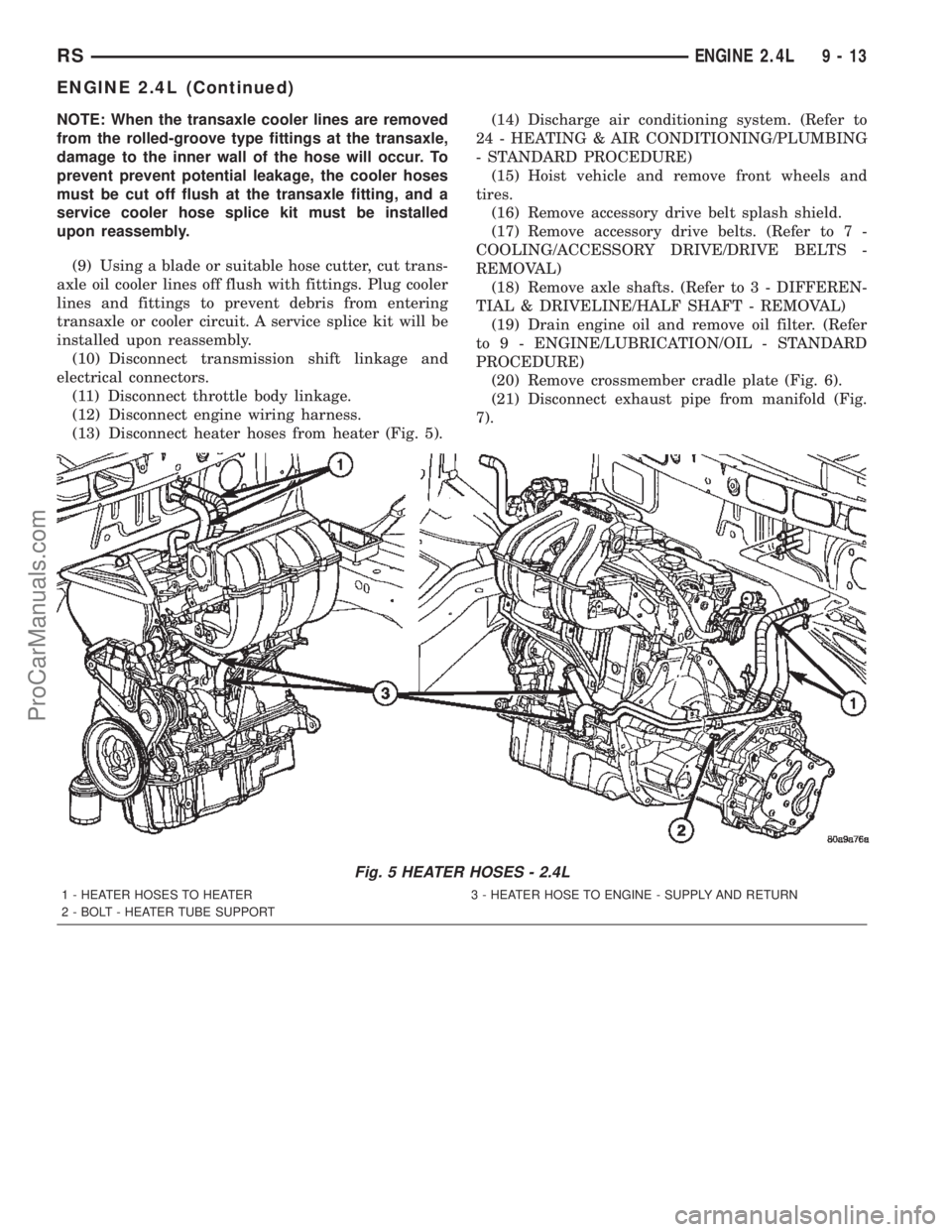
(13) Disconnect heater hoses from heater (Fig. 5).(14) Discharge air conditioning system. (Refer to
24 - HEATING & AIR CONDITIONING/PLUMBING
- STANDARD PROCEDURE)
(15) Hoist vehicle and remove front wheels and
tires.
(16) Remove accessory drive belt splash shield.
(17) Remove accessory drive belts. (Refer to 7 -
COOLING/ACCESSORY DRIVE/DRIVE BELTS -
REMOVAL)
(18) Remove axle shafts. (Refer to 3 - DIFFEREN-
TIAL & DRIVELINE/HALF SHAFT - REMOVAL)
(19) Drain engine oil and remove oil filter. (Refer
to 9 - ENGINE/LUBRICATION/OIL - STANDARD
PROCEDURE)
(20) Remove crossmember cradle plate (Fig. 6).
(21) Disconnect exhaust pipe from manifold (Fig.
7).
Fig. 5 HEATER HOSES - 2.4L
1 - HEATER HOSES TO HEATER 3 - HEATER HOSE TO ENGINE - SUPPLY AND RETURN
2 - BOLT - HEATER TUBE SUPPORT
RSENGINE 2.4L9-13
ENGINE 2.4L (Continued)
ProCarManuals.com
Page 1288 of 2399

REMOVAL - ENGINE ASSEMBLY
(1) Perform fuel pressure release procedure (Refer
to 14 - FUEL SYSTEM/FUEL DELIVERY - STAN-
DARD PROCEDURE).
(2) Disconnect negative battery cable.
(3) Remove air cleaner and hoses.
(4) Disconnect the fuel line from fuel rail (Refer to
14 - FUEL SYSTEM/FUEL DELIVERY/QUICK
CONNECT FITTING - STANDARD PROCEDURE).
(5) Remove the wiper module (Refer to 8 - ELEC-
TRICAL/WIPERS/WASHERS/WIPER MODULE -
REMOVAL).
(6) Block off heater hoses to the rear heater sys-
tem using pinch-off pliers (if equipped).
(7) Drain the cooling system (Refer to 7 - COOL-
ING - STANDARD PROCEDURE).
(8) Disconnect the heater hoses.
(9) Remove the radiator upper support crossmem-
ber (Refer to 23 - BODY/EXTERIOR/GRILLE OPEN-
ING REINFORCEMENT - REMOVAL).
(10) Remove the radiator fans (Refer to 7 - COOL-
ING/ENGINE/RADIATOR FAN - REMOVAL).
(11) Disconnect the throttle cables from the throt-
tle body.
(12) Disconnect the MAP, IAC, and TPS electrical
connectors.
(13) Disconnect the EGR transducer electrical con-
nector (if equipped).
(14) Disconnect the vacuum hoses from throttle
body.
(15) Disconnect the brake booster and speed con-
trol vacuum hoses.
(16) Disengage wire harness clip from the right
side engine mount.
(17) Remove the power steering reservoir from
mounting position and set aside.Do notdisconnect
hose.
(18) Disconnect ground strap from rear of cylinder
head.
(19) Disconnect engine coolant temperature (ECT)
sensor and ignition coil electrical connectors.
(20) Disconnect the fuel injector electrical harness
connector and disengage clip from support bracket.
(21) Disconnect camshaft and crankshaft position
sensor electrical connectors.
(22) Evacuate air conditioning system. Refer to 24
- HEATING & AIR CONDITIONING.
(23) Disconnect A/C compressor electrical connec-
tor.(24) Disconnect the A/C lines from compressor.
Cover and seal all openings of hoses and compressor.
(25) Remove the radiator upper hose.
(26) Disengage electrical harness clip at transaxle
dipstick tube.
(27) Remove transaxle dipstick tube. Seal opening
using a suitable plug.
NOTE: When the transaxle cooler lines are removed
from the rolled-groove type fittings at the transaxle,
damage to the inner wall of the hose will occur. To
prevent prevent potential leakage, the cooler hoses
must be cut off flush at the transaxle fitting, and a
service cooler hose splice kit must be installed
upon reassembly.
(28) Using a blade or suitable hose cutter, cut
transaxle oil cooler lines off flush with fittings. Plug
cooler lines and fittings to prevent debris from enter-
ing transaxle or cooler circuit. A service splice kit will
be installed upon reassembly.
(29) Disconnect transaxle shift linkage and electri-
cal connectors.
(30) Raise vehicle on hoist and drain the engine
oil.
(31) Remove the axle shafts. (Refer to 3 - DIFFER-
ENTIAL & DRIVELINE/HALF SHAFT - REMOVAL)
(32) Remove crossmember cradle plate (Fig. 6).
Fig. 6 Crossmember Cradle Plate
1 - CRADLE PLATE
RSENGINE 3.3/3.8L9-87
ENGINE 3.3/3.8L (Continued)
ProCarManuals.com
Page 1366 of 2399

(17) Remove battery shield.
(18) Remove charge air cooler outlet hose.
(19) Remove charge air cooler inlet hose (Fig. 6).
(20) Disconnect upper radiator hose at engine (Fig.
7).
(21) Disconnect lower radiator hose at engine (Fig.
7).
(22) Disconnet brake booster vacuum supply hose.
(23) Disconnect heater core return hose at engine.
(24) Disconnect egr solenoid vacuum line at brake
booster check valve.
(25) Disconnect fuel injector, cam sensor, boost
pressure/intake air temp sensor, fuel rail high pres-
sure, and egr solenoid connectors (Fig. 8).
(26) Disconnect generator electrical connectors.
(27) Disconnect coolant temp sensor and glow plug
electrical connectors.
(28) Disconnect injection pump and A/C compres-
sor electrical connectors.
(29) Disconnect starter electrical connectors.
(30) Disconnect ground wires at engine block.
(31) Raise vehicle on hoist.
(32) Disconnect oil temp sensor, oil pressure sen-
sor, engine speed sensor, and vehicle speed sensor
electrical connector (Fig. 9).(33) Remove front wheels.
(34) Remove the suspension cradle assembly (Refer
to 13 - FRAME & BUMPERS/FRAME/ENGINE
CRADLE CROSSMEMBER - REMOVAL).
(35) Remove both axle shaft assemblies (Refer to 3
- DIFFERENTIAL & DRIVELINE/HALF SHAFT -
REMOVAL).
(36) Disconnect the clutch slave cylinder quick dis-
connect line (RHD only)(Refer to 6 - CLUTCH/SLAVE
CYLINDER - REMOVAL).
(37) Disconnect reverse lamp connector.
(38) Disconnect shifter cables at the tranmission
(Refer to 21 - TRANSMISSION/TRANSAXLE/MAN-
UAL/GEAR SHIFT CABLE - REMOVAL).
(39) Disconnect exhaust pipe from the turbo-
charger downpipe and reposition to right side of vehi-
cle.
(40) Disconnect cabin heater coolant line (Refer to
24 - HEATING & AIR CONDITIONING/CABIN
HEATER/HEATER UNIT - REMOVAL).
(41) Remove front engine mount bracket retaining
bolts from lower radiator support
(42) Lower vehicle. Evacuate the A/C system
(Refer to 24 - HEATING & AIR CONDITIONING/
Fig. 6 CHARGE AIR COOLER HOSES
1 - COOLING MODULE
2 - BYPASS HOSE
3 - UPPER RADIATOR HOSE
4 - CHARGE AIR COOLER OULET HOSE
5 - CHARGE AIR COOLER INLET HOSE
6 - LOWER RADIATOR HOSE
7 - CHARGE AIR COOLER
Fig. 7 UPPER AND LOWER RADIATOR HOSES
1 - COOLANT BYPASS HOSE
2 - RADIATOR ASSEMBLY
3 - UPPER RADIATOR HOSE
4 - COOLING FAN
5 - LOWER RADIATOR HOSE
6 - CHARGE AIR COOLER
7 - RADIATOR BRACKET
RGENGINE9a-5
ENGINE 2.5L TURBO DIESEL (Continued)
ProCarManuals.com
Page 1368 of 2399

INSTALLATION
INSTALLATION - 2.5L TURBO DIESEL ENGINE
(1) Reassembly engine and transmission assembly
and install on engine cradle.
(2) Position engine and cradle assembly under
vehicle.
(3) Slowly lower the vehicle down over the engine
and cradle assembly.
(4) Install right engine mount bolts. Torque to
54N´m (40 ft. lbs.)
(5) Install left engine mount through bolt. Torque
to 75N´m (55 ft. lbs.)
(6) Raise vehicle and engine from engine cradle.
(7) Attach front engine mount bracket to lower
radiator support. Torque to 54N´m (40 ft. lbs.)
(8) Connect cabin heater coolant hose.
(9) Connect exhaust pipe to the turbocharger
downpipe flange. Torque to 28 N´m (250 in. lbs.)
(10) Connect reverse lamp electrical connector at
transmission.
(11) Connect both shifter cables (Refer to 21 -
TRANSMISSION/TRANSAXLE/MANUAL/GEAR
SHIFT CABLE - INSTALLATION).
(12) Connect the clutch slave cylinder quick dis-
connect connector (RHD only)(Refer to 6 - CLUTCH/
SLAVE CYLINDER - INSTALLATION).
(13) Install engine harness into bracket on trans-
mission.
(14) Lower vehicle.
(15) Connect fuel supply and return lines.
(16) Connect A/C lines to A/C compressor. Torque
to 23N´m (17 ft. lbs.)
(17) Route engine wiring harnes to proper location.
(18) Connect engine harness ground cables to
engine block
(19) Connect starter solenoid electrical connector
and battery feed wire to starter. Torque to 10N´m (90
in. lbs.)
(20) Connect A/C compressor, injection pump, glow
plugs, and coolant temperature sensor electrical con-
nectors.
(21) Connect generator electrical connector. Torque
to 9N´m (75 in. lbs.)
(22) Connect the fuel injector, fuel pressure sensor,
boost pressure/intake air temp sensor, cam sensor,
and egr solenoid electrical connectors (Fig. 8).
(23) Connect egr solenoid vacuum supply line to
brake boost vacuum supply line.(24) Connect brake booster vacuum supply line.
(25) Connect heater core return hose to coolant
pipe.
(26) Connect lower radiator hose to engine (Fig. 7).
(27) Install charger air cooler inlet hose (Fig. 6).
(28) Install charge air cooler outlet hose (Fig. 6).
(29) Connect upper radiator hose to engine (Fig.
7).
(30) Install battery shield.
(31) Install coolant reserve pressure container
(Refer to 7 - COOLING/ENGINE/COOLANT RECOV-
ERY PRESS CONTAINER - INSTALLATION).
(32) Install power steering reservoir and bracket
(Fig. 4).
(33) Raise vehicle
(34) Connect oil pressure sensor, oil temperature
sensor, engine speed sensor, and vehicle speed sensor
electrical connector (Fig. 9).
(35) Install suspension cradle in vehicle (Refer to
13 - FRAME & BUMPERS/FRAME/ENGINE CRA-
DLE CROSSMEMBER - INSTALLATION).
(36) Install both axle shaft assemblies (Refer to 3 -
DIFFERENTIAL & DRIVELINE/HALF SHAFT -
INSTALLATION).
(37) Connect the power steering supply, pressure,
and return lines to power steering pump (Fig. 4).
(38) Install the power steering line brackets on oil
pan (Fig. 4).
(39) Install lower splash shield and side panels.
(40) Install both front wheel and tire assemblies.
(41) Lower vehicle.
(42) Install air cleaner housing, MAF sensor, and
air intake tube assembly (Fig. 3).
(43) Refill transmission to proper level (Refer to 21
- TRANSMISSION/TRANSAXLE/MANUAL/FLUID -
STANDARD PROCEDURE).
(44) Refill engine coolant (Refer to 7 - COOLING/
ENGINE/COOLANT - STANDARD PROCEDURE).
(45) Recharge A/C system (Refer to 24 - HEATING
& AIR CONDITIONING/PLUMBING/REFRIGER-
ANT - STANDARD PROCEDURE) .
(46) Install engine cover (Refer to 9 - ENGINE -
INSTALLATION) (Fig. 2).
(47) Connect negative battery cable.
INSTALLATION - ENGINE COVER
(1) Install engine cover on engine.
(2) Install the engine cover mounting bolts (Fig.
10).
RGENGINE9a-7
ENGINE 2.5L TURBO DIESEL (Continued)
ProCarManuals.com