key CHRYSLER TOWN AND COUNTRY 2002 Service Manual
[x] Cancel search | Manufacturer: CHRYSLER, Model Year: 2002, Model line: TOWN AND COUNTRY, Model: CHRYSLER TOWN AND COUNTRY 2002Pages: 2399, PDF Size: 57.96 MB
Page 141 of 2399
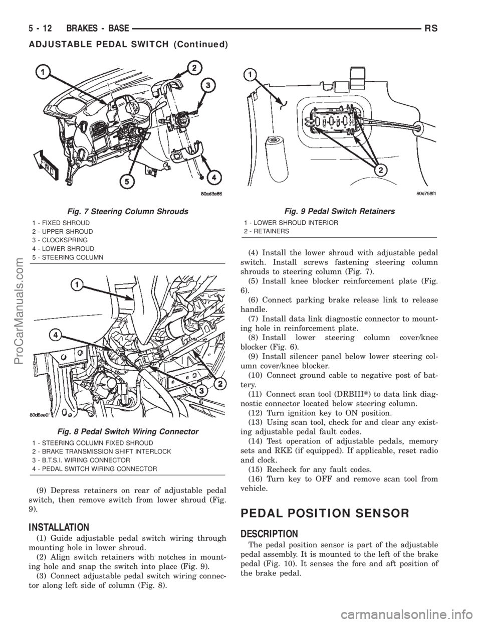
(9) Depress retainers on rear of adjustable pedal
switch, then remove switch from lower shroud (Fig.
9).
INSTALLATION
(1) Guide adjustable pedal switch wiring through
mounting hole in lower shroud.
(2) Align switch retainers with notches in mount-
ing hole and snap the switch into place (Fig. 9).
(3) Connect adjustable pedal switch wiring connec-
tor along left side of column (Fig. 8).(4) Install the lower shroud with adjustable pedal
switch. Install screws fastening steering column
shrouds to steering column (Fig. 7).
(5) Install knee blocker reinforcement plate (Fig.
6).
(6) Connect parking brake release link to release
handle.
(7) Install data link diagnostic connector to mount-
ing hole in reinforcement plate.
(8) Install lower steering column cover/knee
blocker (Fig. 6).
(9) Install silencer panel below lower steering col-
umn cover/knee blocker.
(10) Connect ground cable to negative post of bat-
tery.
(11) Connect scan tool (DRBIIIt) to data link diag-
nostic connector located below steering column.
(12) Turn ignition key to ON position.
(13) Using scan tool, check for and clear any exist-
ing adjustable pedal fault codes.
(14) Test operation of adjustable pedals, memory
sets and RKE (if equipped). If applicable, reset radio
and clock.
(15) Recheck for any fault codes.
(16) Turn key to OFF and remove scan tool from
vehicle.
PEDAL POSITION SENSOR
DESCRIPTION
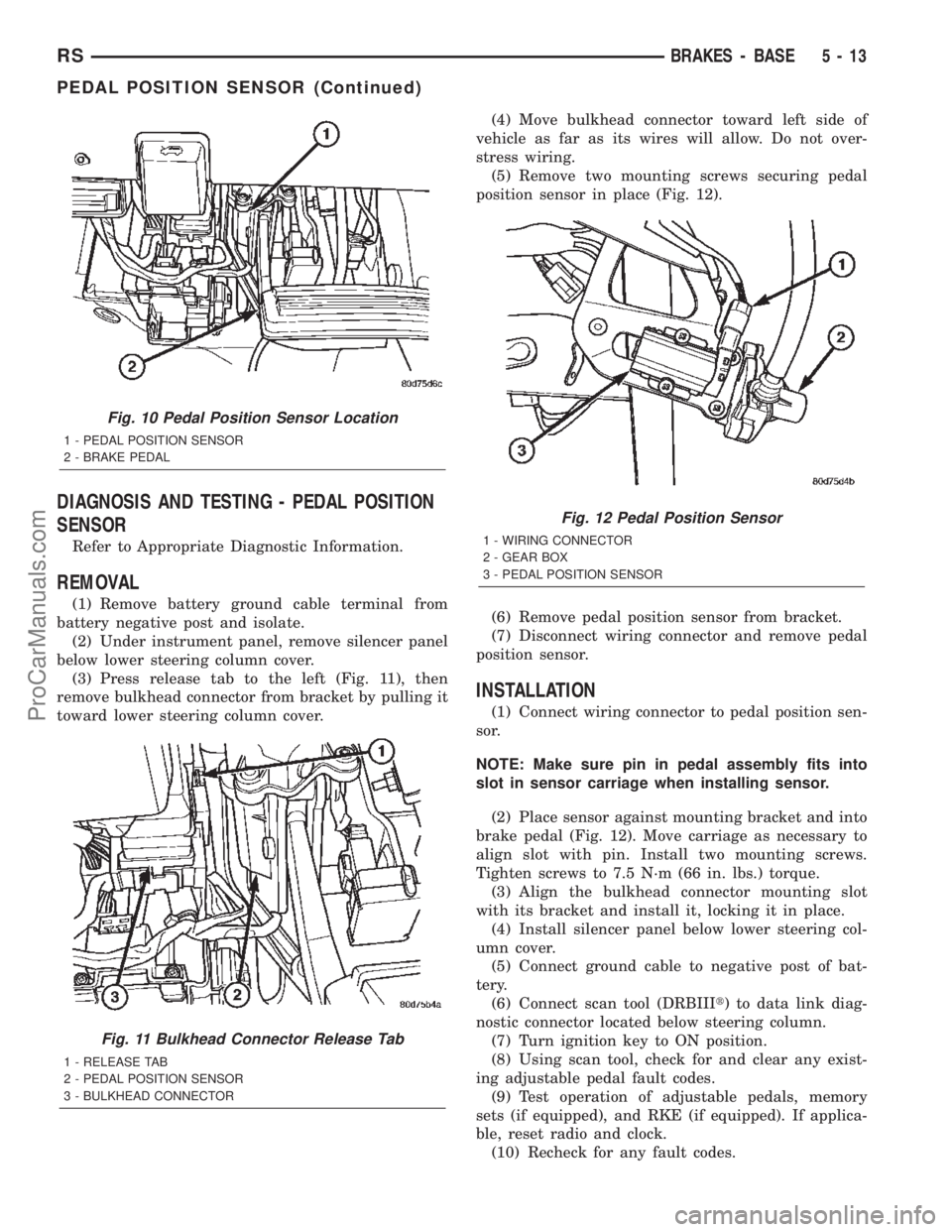
The pedal position sensor is part of the adjustable
pedal assembly. It is mounted to the left of the brake
pedal (Fig. 10). It senses the fore and aft position of
the brake pedal.
Fig. 7 Steering Column Shrouds
1 - FIXED SHROUD
2 - UPPER SHROUD
3 - CLOCKSPRING
4 - LOWER SHROUD
5 - STEERING COLUMN
Fig. 8 Pedal Switch Wiring Connector
1 - STEERING COLUMN FIXED SHROUD
2 - BRAKE TRANSMISSION SHIFT INTERLOCK
3 - B.T.S.I. WIRING CONNECTOR
4 - PEDAL SWITCH WIRING CONNECTOR
Fig. 9 Pedal Switch Retainers
1 - LOWER SHROUD INTERIOR
2 - RETAINERS
5 - 12 BRAKES - BASERS
ADJUSTABLE PEDAL SWITCH (Continued)
ProCarManuals.com
Page 142 of 2399
DIAGNOSIS AND TESTING - PEDAL POSITION
SENSOR
Refer to Appropriate Diagnostic Information.
REMOVAL
(1) Remove battery ground cable terminal from
battery negative post and isolate.
(2) Under instrument panel, remove silencer panel
below lower steering column cover.
(3) Press release tab to the left (Fig. 11), then
remove bulkhead connector from bracket by pulling it
toward lower steering column cover.(4) Move bulkhead connector toward left side of
vehicle as far as its wires will allow. Do not over-
stress wiring.
(5) Remove two mounting screws securing pedal
position sensor in place (Fig. 12).
(6) Remove pedal position sensor from bracket.
(7) Disconnect wiring connector and remove pedal
position sensor.
INSTALLATION
(1) Connect wiring connector to pedal position sen-
sor.
NOTE: Make sure pin in pedal assembly fits into
slot in sensor carriage when installing sensor.
(2) Place sensor against mounting bracket and into
brake pedal (Fig. 12). Move carriage as necessary to
align slot with pin. Install two mounting screws.
Tighten screws to 7.5 N´m (66 in. lbs.) torque.
(3) Align the bulkhead connector mounting slot
with its bracket and install it, locking it in place.
(4) Install silencer panel below lower steering col-
umn cover.
(5) Connect ground cable to negative post of bat-
tery.
(6) Connect scan tool (DRBIIIt) to data link diag-
nostic connector located below steering column.
(7) Turn ignition key to ON position.
(8) Using scan tool, check for and clear any exist-
ing adjustable pedal fault codes.
(9) Test operation of adjustable pedals, memory
sets (if equipped), and RKE (if equipped). If applica-
ble, reset radio and clock.
(10) Recheck for any fault codes.
Fig. 10 Pedal Position Sensor Location
1 - PEDAL POSITION SENSOR
2 - BRAKE PEDAL
Fig. 11 Bulkhead Connector Release Tab
1 - RELEASE TAB
2 - PEDAL POSITION SENSOR
3 - BULKHEAD CONNECTOR
Fig. 12 Pedal Position Sensor
1 - WIRING CONNECTOR
2 - GEAR BOX
3 - PEDAL POSITION SENSOR
RSBRAKES - BASE5-13
PEDAL POSITION SENSOR (Continued)
ProCarManuals.com
Page 143 of 2399
(11) Turn key to OFF and remove scan tool from
vehicle.
(12) Road test the vehicle to ensure proper opera-
tion of the adjustable brake system.
HYDRAULIC/MECHANICAL
DESCRIPTION
DESCRIPTION - DISC BRAKES (FRONT)
Each front disc brake consists of the following com-
ponents:
²Brake Rotor
²Brake Caliper
²Brake Caliper Adapter
²Shoes (Pads)
There are two non-interchangeable front disc brake
systems depending on whether the vehicle is
equipped with rear drum or rear disc brakes. Vehi-
cles with the front disc/rear drum brake combination
utilize a system manufactured by TRW. Vehicles with
front disc/rear disc brakes utilize a system manufac-
tured by Continental Teves.
CAUTION: Components used on the disc/drum
combination brakes are not interchangeable with
the disc/disc combination brakes. The two different
systems must not be mixed. Improper performance,
noise and increased stopping distance can occur.
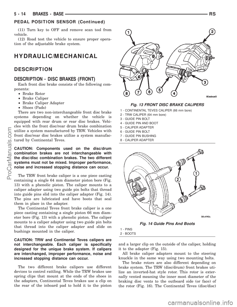
The TRW front brake caliper is a one piece casting
containing a single 64 mm diameter piston bore (Fig.
13) with a phenolic piston. The caliper mounts to a
caliper adapter using two guide pin bolts that thread
into guide pins slid into the caliper adapter (Fig. 14).
The pins are lubricated and have boots that seal
them in place in the adapter.
The Continental Teves front brake caliper is a one
piece casting containing a single piston 66 mm diam-
eter bore (Fig. 13) with a phenolic piston. The caliper
mounts to a caliper adapter using two guide pin bolts
that thread into the caliper adapter and slide on
bushings mounted in the caliper.
CAUTION: TRW and Continental Teves calipers are
not interchangeable. Each caliper is specifically
designed for the unique brake system. If calipers
are interchanged, improper performance, noise and
increased stopping distance can occur.
The two different brake calipers use different
devices to control rattling. While the TRW brakes use
spring clips that mount at the ends of the shoes in
the adapters, Continental Teves brakes use a clip on
the rear of the inboard pad to hold it to the pistonand a larger clip on the outside of the caliper, holding
it to the adapter (Fig. 15).
All brake caliper adapters mount to the steering
knuckle in the same way using two mounting bolts.
The brake rotors are also different depending on
brake system. The TRW (disc/drum) front brakes uti-
lize an inverted-hat style rotor. This rotor is exter-
nally vented meaning the inner most diameter of the
braking disc vents to the outboard side (or face) of
the rotor (Fig. 16). The Continental Teves (disc/disc)
Fig. 13 FRONT DISC BRAKE CALIPERS
1 - CONTINENTAL TEVES CALIPER (66 mm bore)
2 - TRW CALIPER (64 mm bore)
3 - GUIDE PIN BOLT
4 - GUIDE PIN AND BOOT
5 - CALIPER ADAPTER
6 - GUIDE PIN BOLT
7 - GUIDE PIN BUSHING
8 - CALIPER ADAPTER
Fig. 14 Guide Pins And Boots
1 - PINS
2 - BOOTS
5 - 14 BRAKES - BASERS
PEDAL POSITION SENSOR (Continued)
ProCarManuals.com
Page 171 of 2399
(5) Install wiring harness connector to brake fluid
level switch mounted in brake fluid reservoir (Fig.
57).
(6) Install battery, clamp and nut.
(7) Install battery shield.
(8) Connect positive battery terminal.
(9) Connect negative battery terminal.
(10) Fill master cylinder with clean, fresh Mopart
Brake Fluid or equivalent.
(11) Road test vehicle to ensure proper operation of
brakes.
INSTALLATION - RHD
CAUTION: Different types of master cylinders are
used on this vehicle depending on brake options. If
a new master cylinder is being installed, be sure it
is the correct master cylinder for the type of brake
system the vehicle is equipped with.
CAUTION: When replacing the master cylinder on a
vehicle, a NEW vacuum seal MUST be installed on
the master cylinder.
(1) Install a NEW vacuum seal on master cylinder
making sure seal fits squarely in groove of master
cylinder casting.
(2) Position master cylinder on studs of power
brake booster, aligning booster push rod with master
cylinder piston.
(3) Install the two master cylinder mounting nuts
(Fig. 59). Tighten both mounting nuts to a torque of
25 N´m (225 in. lbs.).
CAUTION: When tightening the primary and sec-
ondary brake tube nuts at master cylinder, be sure
brake tubes do not contact any other components
within the vehicle and that there is slack in the flex-
ible sections of the tubes. This is required due to
the movement between the ABS ICU and the master
cylinder while the vehicle is in motion.
(4) Connect primary and secondary brake tubes to
master cylinder primary and secondary ports (Fig.
59). Brake tubes must be held securely when tight-
ened to control orientation of flex section. Tighten
tube nuts to a torque of 17 N´m (145 in. lbs.).
(5) Install wiring harness connector to brake fluid
level switch mounted in brake fluid reservoir (Fig.
55).
(6) Install battery, clamp and nut.
(7) Install battery shield.
(8) Connect positive battery terminal.
(9) Connect negative battery terminal.
(10) Fill master cylinder with clean, fresh Mopart
Brake Fluid or equivalent.(11) Road test vehicle to ensure proper operation of
brakes.
PEDAL - ADJUSTABLE
DESCRIPTION
The Adjustable Pedals System (APS) is designed to
enable the fore and aft repositioning of the brake and
accelerator pedals. This results in improved ergonom-
ics in relation to the steering wheel for taller and
shorter drivers. Being able to adjust the pedal posi-
tions also allows the driver to set steering wheel tilt
and seat position to the most comfortable position.
The effort required for pedal application will not
change regardless of pedal position.
The adjustable pedal system allows the pedals to
adjust up to 3 inches (75 mm) at a rate of approxi-
mately 0.4 in./sec. (9 mm/sec.). An adjustment switch
is located on the left side of the steering column
lower shroud.
If the vehicle is equipped with Remote Keyless
Entry (RKE), an optional memory feature is avail-
able.
The serviceable components of the APS are:
²Adjustable pedal assembly (includes motor,
cables, pedals, gear box, sensor and module)
²Adjustable pedal module (Refer to 8 - ELECTRI-
CAL/ELECTRONIC CONTROL MODULES/
ADJUSTABLE PEDAL MODULE)
²Adjustable pedal switch
²Pedal position sensor
OPERATION
Change of pedal position is accomplished by means
of a motor driven screw. Operating the adjustable
pedal switch activates the pedal drive motor. The
pedal drive motor turns a screw that changes the
position of the accelerator pedal. The motor also
drives a cable connected to a gear box that changes
the brake pedal position the same distance as the
accelerator pedal. The pedals can be moved rearward
(closer to the driver) or forward (away from driver).
Each pedal is moved on its activating lever to a posi-
tion where the driver feels most comfortable. The
position and operation of the activating levers are not
changed.
Pedal adjustment is inhibited when the vehicle is
in reverse or when cruise control is engaged. The
Electronic Vehicle Information Center (EVIC) will
display a message when the Adjustable Pedal Module
(APM) is disabled. i.e.:9Adjustable Pedal Disabled -
Cruise Control Engaged9or9Adjustable Pedal Dis-
abled - Vehicle in Reverse9.
Foot pressure or debris can stall pedal adjustment.
In order to avoid damage to system components dur-
5 - 42 BRAKES - BASERS
MASTER CYLINDER (Continued)
ProCarManuals.com
Page 172 of 2399
ing pedal adjustment, the APM will monitor pedal
position sensor voltage. If the APM does not detect
expected voltage change within 3 seconds, it will cut
power to the adjustable pedal motor.
An optional memory feature is available. This
allows storing of one or two preferred pedal positions
in the APS. A preferred position can be stored and
recalled using the door-mounted switches. A stored
pedal position can be recalled (but not stored) using
the Remote Keyless Entry (RKE) if equipped with
the memory feature.
DIAGNOSIS AND TESTING - ADJUSTABLE
PEDAL SYSTEM
Refer to Appropriate Diagnostic Information.
REMOVAL
NOTE: Before proceeding, review all Steering Col-
umn and Airbag Warnings and Cautions. (Refer to
19 - STEERING/COLUMN - WARNING)(Refer to 8 -
ELECTRICAL/RESTRAINTS - WARNING)
(1) Remove battery ground cable terminal from
battery negative post and isolate.
(2) Under instrument panel, remove silencer panel
below lower steering column cover.
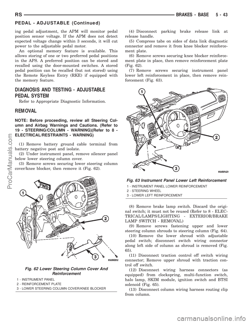
(3) Remove screws securing lower steering column
cover/knee blocker, then remove it (Fig. 62).(4) Disconnect parking brake release link at
release handle.
(5) Compress tabs on sides of data link diagnostic
connector and remove it from knee blocker reinforce-
ment plate.
(6) Remove screws securing knee blocker reinforce-
ment plate in place, then remove reinforcement plate
(Fig. 62).
(7) Remove screws securing instrument panel
lower left reinforcement in place, then remove rein-
forcement (Fig. 63).
(8) Remove brake lamp switch. Discard the origi-
nal switch; it must not be reused (Refer to 8 - ELEC-
TRICAL/LAMPS/LIGHTING - EXTERIOR/BRAKE
LAMP SWITCH - REMOVAL)
(9) Remove screws fastening upper and lower
steering column shrouds to steering column (Fig. 64).
(10) Remove the lower shroud with adjustable
pedal switch; disconnect switch wiring connector
along left side of column as shroud is removed (Fig.
65).
(11) Disconnect traction control off switch wiring
connector; Remove upper shroud with traction con-
trol off switch.
(12) Disconnect wiring harness connectors (as
equipped) from clockspring, multi-function switch,
halo lamp, SKIM module, ignition switch and BTSI
solenoid (Fig. 65).
(13) Disconnect column wiring harness routing clip
from column.
Fig. 62 Lower Steering Column Cover And
Reinforcement
1 - INSTRUMENT PANEL
2 - REINFORCEMENT PLATE
3 - LOWER STEERING COLUMN COVER/KNEE BLOCKER
Fig. 63 Instrument Panel Lower Left Reinforcement
1 - INSTRUMENT PANEL LOWER REINFORCEMENT
2 - STEERING WHEEL
3 - LOWER LEFT REINFORCEMENT
RSBRAKES - BASE5-43
PEDAL - ADJUSTABLE (Continued)
ProCarManuals.com
Page 173 of 2399
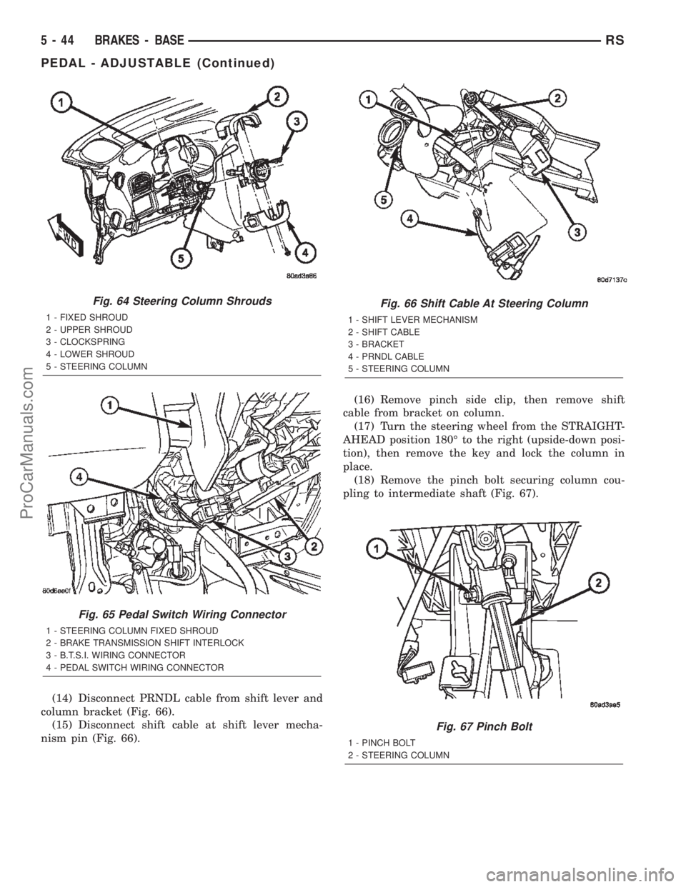
(14) Disconnect PRNDL cable from shift lever and
column bracket (Fig. 66).
(15) Disconnect shift cable at shift lever mecha-
nism pin (Fig. 66).(16) Remove pinch side clip, then remove shift
cable from bracket on column.
(17) Turn the steering wheel from the STRAIGHT-
AHEAD position 180É to the right (upside-down posi-
tion), then remove the key and lock the column in
place.
(18) Remove the pinch bolt securing column cou-
pling to intermediate shaft (Fig. 67).
Fig. 64 Steering Column Shrouds
1 - FIXED SHROUD
2 - UPPER SHROUD
3 - CLOCKSPRING
4 - LOWER SHROUD
5 - STEERING COLUMN
Fig. 65 Pedal Switch Wiring Connector
1 - STEERING COLUMN FIXED SHROUD
2 - BRAKE TRANSMISSION SHIFT INTERLOCK
3 - B.T.S.I. WIRING CONNECTOR
4 - PEDAL SWITCH WIRING CONNECTOR
Fig. 66 Shift Cable At Steering Column
1 - SHIFT LEVER MECHANISM
2 - SHIFT CABLE
3 - BRACKET
4 - PRNDL CABLE
5 - STEERING COLUMN
Fig. 67 Pinch Bolt
1 - PINCH BOLT
2 - STEERING COLUMN
5 - 44 BRAKES - BASERS
PEDAL - ADJUSTABLE (Continued)
ProCarManuals.com
Page 176 of 2399
(27) Install lower steering column cover/knee
blocker (Fig. 62).
(28) Install silencer panel below lower steering col-
umn cover/knee blocker.
NOTE: When reconnecting the battery on a vehicle
that has had the airbag module removed, the fol-
lowing procedure should be used.
(29) Reconnect ground cable to negative post of
battery in following manor:
(a) Connect scan tool (DRBIIIt) to data link
diagnostic connector located below steering column.
(b) Turn ignition key to ON position. Exit vehi-
cle with scan tool leaving scan tool harness
plugged in.
(c) Ensuring that there are no occupants in vehi-
cle, connect ground (-) cable to the negative post of
the battery.
(d) Using scan tool, read and record any airbag
fault codes. Refer to Appropriate Diagnostic Infor-
mation if any faults are found.
(e) Through drivers open window, Reach around
back of steering wheel (between steering wheel and
instrument cluster) and turn ignition key to OFF,
then back ON while observing instrument cluster
airbag indicator lamp. It should go on for six to
eight seconds, then go out. This action indicates
that airbag system is functioning normally. If air-
bag indicator lamp fails to light, blinks on and off,
or goes on and stays on, there is an airbag system
malfunction. Refer to Appropriate Diagnostic Infor-
mation to diagnose the system malfunction.
(30) Using scan tool (DRBIIIt), check for and clear
any existing adjustable pedal fault codes. The adjust-
able pedal system is now activated.
(31) Turn key to OFF and remove scan tool from
vehicle.
(32) Test operation of adjustable pedals, memory
seats (if equipped), RKE (if equipped), and all func-
tions that are steering column operated. If applica-
ble, reset the radio and the clock.
(33) Road test the vehicle to ensure proper opera-
tion of the steering and brake systems.
PEDAL TORQUE SHAFT - RHD
REMOVAL
(1) Remove the instrument panel. (Refer to 23 -
BODY/INSTRUMENT PANEL/INSTRUMENT
PANEL ASSEMBLY - REMOVAL)
(2) Remove the HVAC housing. (Refer to 24 -
HEATING & AIR CONDITIONING/DISTRIBUTION/
HVAC HOUSING - REMOVAL)
(3) Remove the retaining clip at the torque shaft
end of the brake pedal-to-torque shaft link. Removethe link from the torque shaft. Discard the retaining
clip. It is not to be reused. Replace with a new clip
when reassembled.
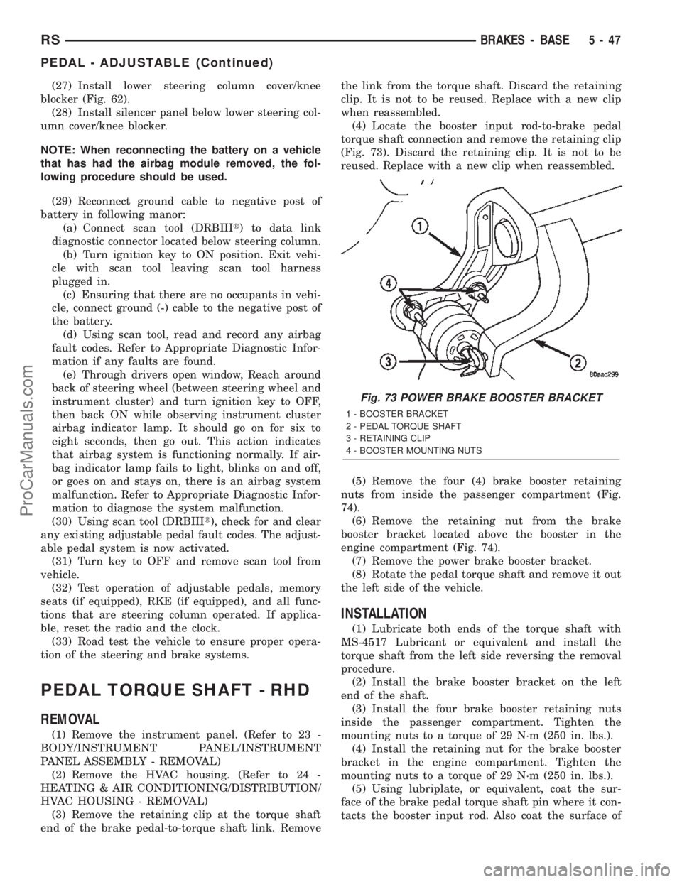
(4) Locate the booster input rod-to-brake pedal
torque shaft connection and remove the retaining clip
(Fig. 73). Discard the retaining clip. It is not to be
reused. Replace with a new clip when reassembled.
(5) Remove the four (4) brake booster retaining
nuts from inside the passenger compartment (Fig.
74).
(6) Remove the retaining nut from the brake
booster bracket located above the booster in the
engine compartment (Fig. 74).
(7) Remove the power brake booster bracket.
(8) Rotate the pedal torque shaft and remove it out
the left side of the vehicle.
INSTALLATION
(1) Lubricate both ends of the torque shaft with
MS-4517 Lubricant or equivalent and install the
torque shaft from the left side reversing the removal
procedure.
(2) Install the brake booster bracket on the left
end of the shaft.
(3) Install the four brake booster retaining nuts
inside the passenger compartment. Tighten the
mounting nuts to a torque of 29 N´m (250 in. lbs.).
(4) Install the retaining nut for the brake booster
bracket in the engine compartment. Tighten the
mounting nuts to a torque of 29 N´m (250 in. lbs.).
(5) Using lubriplate, or equivalent, coat the sur-
face of the brake pedal torque shaft pin where it con-
tacts the booster input rod. Also coat the surface of
Fig. 73 POWER BRAKE BOOSTER BRACKET
1 - BOOSTER BRACKET
2 - PEDAL TORQUE SHAFT
3 - RETAINING CLIP
4 - BOOSTER MOUNTING NUTS
RSBRAKES - BASE5-47
PEDAL - ADJUSTABLE (Continued)
ProCarManuals.com
Page 329 of 2399
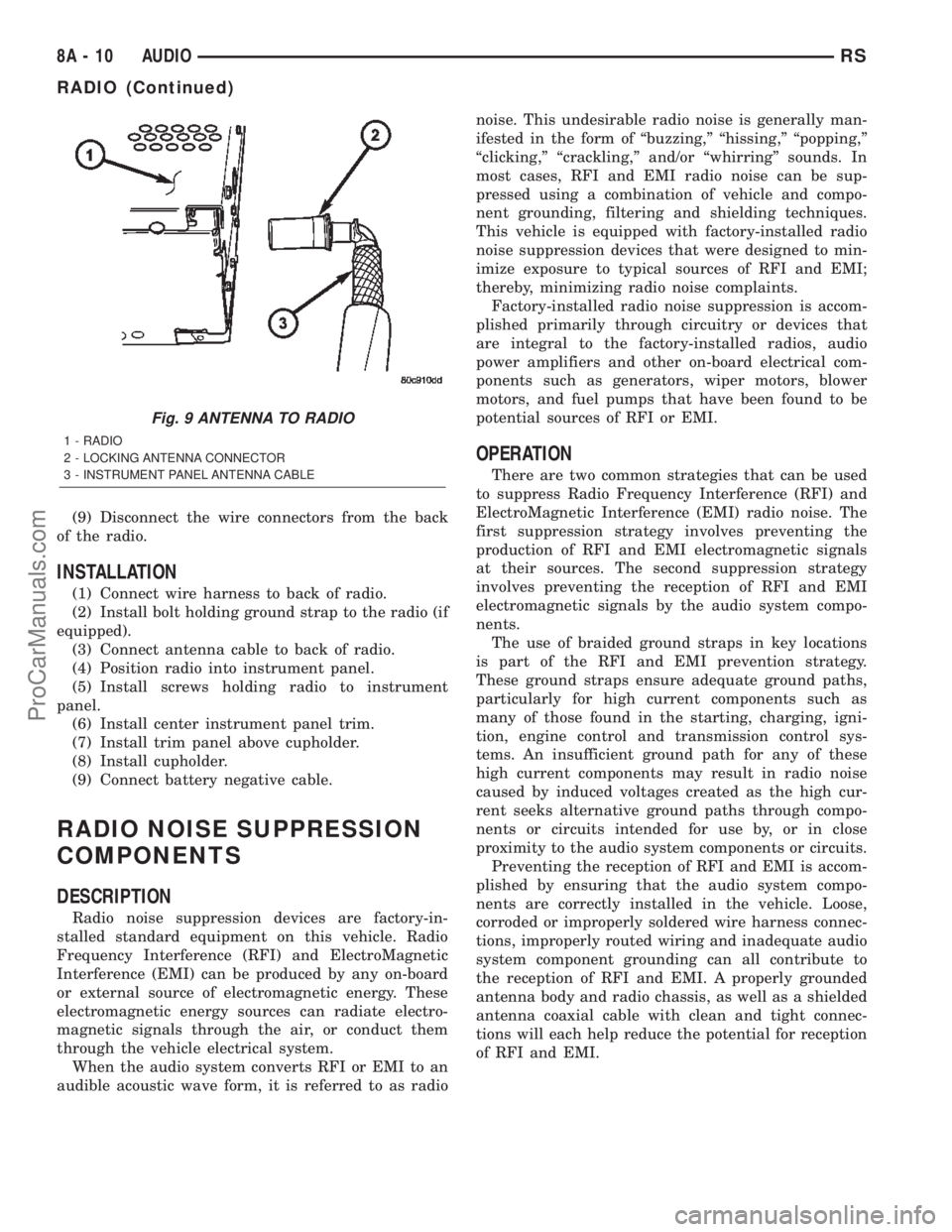
(9) Disconnect the wire connectors from the back
of the radio.
INSTALLATION
(1) Connect wire harness to back of radio.
(2) Install bolt holding ground strap to the radio (if
equipped).
(3) Connect antenna cable to back of radio.
(4) Position radio into instrument panel.
(5) Install screws holding radio to instrument
panel.
(6) Install center instrument panel trim.
(7) Install trim panel above cupholder.
(8) Install cupholder.
(9) Connect battery negative cable.
RADIO NOISE SUPPRESSION
COMPONENTS
DESCRIPTION
Radio noise suppression devices are factory-in-
stalled standard equipment on this vehicle. Radio
Frequency Interference (RFI) and ElectroMagnetic
Interference (EMI) can be produced by any on-board
or external source of electromagnetic energy. These
electromagnetic energy sources can radiate electro-
magnetic signals through the air, or conduct them
through the vehicle electrical system.
When the audio system converts RFI or EMI to an
audible acoustic wave form, it is referred to as radionoise. This undesirable radio noise is generally man-
ifested in the form of ªbuzzing,º ªhissing,º ªpopping,º
ªclicking,º ªcrackling,º and/or ªwhirringº sounds. In
most cases, RFI and EMI radio noise can be sup-
pressed using a combination of vehicle and compo-
nent grounding, filtering and shielding techniques.
This vehicle is equipped with factory-installed radio
noise suppression devices that were designed to min-
imize exposure to typical sources of RFI and EMI;
thereby, minimizing radio noise complaints.
Factory-installed radio noise suppression is accom-
plished primarily through circuitry or devices that
are integral to the factory-installed radios, audio
power amplifiers and other on-board electrical com-
ponents such as generators, wiper motors, blower
motors, and fuel pumps that have been found to be
potential sources of RFI or EMI.
OPERATION
There are two common strategies that can be used
to suppress Radio Frequency Interference (RFI) and
ElectroMagnetic Interference (EMI) radio noise. The
first suppression strategy involves preventing the
production of RFI and EMI electromagnetic signals
at their sources. The second suppression strategy
involves preventing the reception of RFI and EMI
electromagnetic signals by the audio system compo-
nents.
The use of braided ground straps in key locations
is part of the RFI and EMI prevention strategy.
These ground straps ensure adequate ground paths,
particularly for high current components such as
many of those found in the starting, charging, igni-
tion, engine control and transmission control sys-
tems. An insufficient ground path for any of these
high current components may result in radio noise
caused by induced voltages created as the high cur-
rent seeks alternative ground paths through compo-
nents or circuits intended for use by, or in close
proximity to the audio system components or circuits.
Preventing the reception of RFI and EMI is accom-
plished by ensuring that the audio system compo-
nents are correctly installed in the vehicle. Loose,
corroded or improperly soldered wire harness connec-
tions, improperly routed wiring and inadequate audio
system component grounding can all contribute to
the reception of RFI and EMI. A properly grounded
antenna body and radio chassis, as well as a shielded
antenna coaxial cable with clean and tight connec-
tions will each help reduce the potential for reception
of RFI and EMI.
Fig. 9 ANTENNA TO RADIO
1 - RADIO
2 - LOCKING ANTENNA CONNECTOR
3 - INSTRUMENT PANEL ANTENNA CABLE
8A - 10 AUDIORS
RADIO (Continued)
ProCarManuals.com
Page 334 of 2399
CHIME/BUZZER
TABLE OF CONTENTS
page page
CHIME/BUZZER
DESCRIPTION..........................1
OPERATION............................1
WARNING.............................1
DIAGNOSIS AND TESTING
DIAGNOSIS AND TESTING - CHIME
SYSTEM.............................1
DIAGNOSIS AND TESTING - DOME LAMP
ON CHIME............................2
DIAGNOSIS AND TESTING - ENGINE
TEMPERATURE CRITICAL CHIME..........2
DIAGNOSIS AND TESTING - EXTERIOR
LAMPS ON CHIME.....................2
DIAGNOSIS AND TESTING - KEY-IN
IGNITION CHIME.......................2DIAGNOSIS AND TESTING - LOW OIL
PRESSURE CHIME.....................3
DIAGNOSIS AND TESTING - SEAT BELT
CHIME...............................3
DIAGNOSIS AND TESTING - SEAT BELT
LAMP...............................3
DIAGNOSIS AND TESTING - TIRE
PRESSURE MONITOR..................3
DIAGNOSIS AND TESTING - TURN SIGNAL
ON CHIME............................3
DIAGNOSIS AND TESTING - WARNING
LAMP ANNOUNCEMENT CHIME...........4
CHIME/BUZZER
DESCRIPTION
The chime/buzzer system provides the driver with
warning chimes for:
²Seat Belt
²Exterior Lamps ON
²Key-In Ignition
²Engine Temperature Critical
²Turn Signals ON
²Dome Lamp ON
²Low Oil Pressure
²High Speed Warning
²Warning Lamp Announcement
²Key-In Accessory
²Low/High Tire Pressure
²Service Tire Pressure Monitor (TPM)
HIGH SPEED WARNING - EXPORT
The chime will sound, acting as a warning to the
driver that the vehicle speed has exceeded 120 3
kph (75 2 mph).
OPERATION
The Chime/Buzzer Warning System is diagnosed
using a DRB llltscan tool. Refer to the proper Body
Diagnostic Procedures Manual.
HIGH SPEED WARNING - EXPORT
When the vehicle speed sensor sees 120 3kph
(75 2 mph), it sends a PCI data bus message to the
Body Control Module (BCM). The BCM then turns onthe chime to let the driver know that the vehicle has
reached a speed greater than 120 3kph(75 2
mph). This audible message will continue until the
vehicle is slowed below the predetermined speed.
WARNING
WARNING: ON VEHICLES EQUIPPED WITH AIR-
BAGS, DISABLE THE AIRBAG SYSTEM BEFORE
ATTEMPTING ANY STEERING WHEEL, STEERING
COLUMN, OR INSTRUMENT PANEL COMPONENT
DIAGNOSIS OR SERVICE. DISCONNECT AND ISO-
LATE THE BATTERY NEGATIVE (GROUND) CABLE,
THEN WAIT TWO MINUTES FOR THE AIRBAG SYS-
TEM CAPACITOR TO DISCHARGE BEFORE PER-
FORMING FURTHER DIAGNOSIS OR SERVICE. THIS
IS THE ONLY SURE WAY TO DISABLE THE AIRBAG
SYSTEM. FAILURE TO TAKE THE PROPER PRE-
CAUTIONS COULD RESULT IN ACCIDENTAL AIR-
BAG DEPLOYMENT AND POSSIBLE PERSONAL
INJURY.
DIAGNOSIS AND TESTING
DIAGNOSIS AND TESTING - CHIME SYSTEM
NO TONE WHEN IGNITION SWITCH IS TURNED ON
AND DRIVER'S SEAT BELT IS NOT BUCKLED.
(1) Using a DRB llltscan tool, actuate chime
(BCM actuates).
(2) Using a voltmeter, check for voltage:
RSCHIME/BUZZER8B-1
ProCarManuals.com
Page 335 of 2399
(a) BCM has two battery feeds at pin 1 and pin
5 of the 6±way connector.
(b) Pin 5 of the (BX2) 32 way connector of the
BCM for ignition feed.
(c) Check voltage (PX2) connector, pin 34 for 12v.
(d) If voltage OK, go to step Step 3
(e) If NO voltage repair as necessary. Refer to
the appropriate wiring information. The wiring
information includes wiring diagrams, proper wire
and connector repair procedures, further details on
wire harness routing and retention, as well as pin-
out and location views for the various wire harness
connectors, splices and grounds.
(3) Check driver's seat belt buckle switch input
(form ORC) for a closed circuit when not buckled. If
input not seen, look for open in wiring or switch. The
switch is grounded when belt is not buckled.
(4) Verify PCI data bus communication between
ORC and BCM.
NO FASTEN SEAT BELT LAMP WHEN IGNITION
SWITCH IS TURNED ON.
(1) Check for burned out lamp.
(2) Using a voltmeter check for voltage at the clus-
ter conncctor:
(a) Pin 2 of the mechanical instrument cluster
for battery feed.
(b) Pin 11 of the mechanical instrument cluster
for ignition voltage.
(3) Repair as necessary.
FASTEN SEAT BELT LAMP OR TONE CONTINUES
FOR MORE THAN 10 SECONDS AFTER SEAT
BELTS ARE FASTENED AND DRIVER'S DOOR IS
CLOSED.
Refer to the proper Body Diagnostic Procedures
manual.
NO TONE WHEN PARK OR HEADLAMPS ARE ON
AND DRIVER'S DOOR IS OPEN.
Make sure ignition is in lock position with the key
removed.
(1) Check the BCM DTC's and BCM sensors to
verify the door is open. Repair as necessary.
(2) Actuate Chime (BCM actuates).
(3) Inspect BCM connectors and wires for proper
connection.
(4) Measure with a voltmeter the voltage (12v) on
BCM connector (PX2) pin 34 with harness connected.
DIAGNOSIS AND TESTING - DOME LAMP ON
CHIME
The dome lamp on chime will warn the driver that
the dome lamps have been left on.When the ignition is OFF and the key is out of the
ignition:
²Driver's door OPEN (door ajar switch is closed to
ground) and
²Dome lamps are ON (dome lamp switch is closed
to ground),
The chime will sound continuously until the driv-
ers door is closed, dome lamps turned OFF or until
the battery protection time out of 15 minutes has
expired. Chime rate: 168 to 192 chimes per minute.
DIAGNOSIS AND TESTING - ENGINE
TEMPERATURE CRITICAL CHIME
The engine temperature critical chime will warn
the driver that the vehicle's engine is overheating.
While monitoring the coolant temperature, the Pow-
ertrain Control Module (PCM) will send on the PCI
data bus as engine temperature every 1.376 seconds
to the cluster. The MIC calculates engine tempera-
ture and determines if a warning should occur. This
feature is functional only with the Ignition Switch in
the Run/Start position.
When the engine temperature reaches 122ÉC
(252ÉF) the MIC requests a chime from the BCM and
the engine temperature lamp comes ON. The MIC
turns OFF the lamp when the engine temperature
reaches 117ÉC (242ÉF). The MIC will chime continu-
ously (request from the BCM). The chime will turn
OFF after four minutes or when the temperature
reaches 117ÉC (242ÉF), which ever occurs first.
DIAGNOSIS AND TESTING - EXTERIOR LAMPS
ON CHIME
The exterior lamp on chime will warn the driver
that the exterior lights have been left on.
With the ignition switch OFF/key out of ignition:
²Driver's door is open (door ajar switch is closed
to ground)
²Parking lamps or headlamps ON (parking lamp
switch is closed to ground)
The chime will sound until lights are turned OFF,
driver's door closed or until the battery protection
time out of 3 minutes has expired.
Chime rate: 168 to 192 chimes per minute.
To test the exterior lamps left on function:
²Turn ignition off
²Remove ignition key
²Turn exterior lamps on with driver's door open.
Chime should sound until lamps are turned off or
driver's door is closed.
DIAGNOSIS AND TESTING - KEY-IN IGNITION
CHIME
The key-in ignition chime will act as a warning to
the driver that the ignition key has been left in the
8B - 2 CHIME/BUZZERRS
CHIME/BUZZER (Continued)
ProCarManuals.com