ESP CHRYSLER TOWN AND COUNTRY 2011 5.G User Guide
[x] Cancel search | Manufacturer: CHRYSLER, Model Year: 2011, Model line: TOWN AND COUNTRY, Model: CHRYSLER TOWN AND COUNTRY 2011 5.GPages: 100, PDF Size: 3.24 MB
Page 5 of 100
Vehicles Sold In Canada
With respect to any vehicles sold in Canada, the name Chrysler Group LLC shall be deemed to be
deleted and the name Chrysler Canada Inc. used in substitution therefore.
WARNING!
• Pedals that cannot move freely can cause loss of vehicle control and increase the risk ofserious personal injury.
• Always make sure that objects cannot fall into the driver foot well while the vehicle is moving. Objects can become trapped under the brake pedal and accelerator pedal
causing a loss of vehicle control.
• Failure to properly follow floor mat installation or mounting can cause interference with the brake pedal and accelerator pedal operation causing loss of control of the vehicle.
• Never use the ‘PARK’ position as a substitute for the parking brake. Always apply the parking brake fully when parked to guard against vehicle movement and possible injury
or damage.
• Refer to your Owner's Manual on the DVD for further details.
USE OF AFTERMARKET PRODUCTS (ELECTRONICS)
The use of aftermarket devices including cell phones, MP3 players, GPS systems, or chargers may
affect the performance of on-board wireless features including Keyless Enter-N-Go and Remote
Start range. If you are experiencing difficulties with any of your wireless features, try disconnecting
your aftermarket devices to see if the situation improves. If your symptoms persist, please see an
authorized dealer.
CHRYSLER, DODGE, JEEP, RAM TRUCK, ATF+4, MOPAR and Uconnect are registered
trademarks of Chrysler Group LLC.
COPYRIGHT ©2011 CHRYSLER GROUP LLC
INTRODUCTION/WELCOME
03
Page 20 of 100
WARNING!
• Persons who are unable to feel pain to the skin because of advanced age, chronic illness,diabetes, spinal cord injury, medication, alcohol use, exhaustion or other physical
conditions must exercise care when using the seat heater. It may cause burns even at low
temperatures, especially if used for long periods of time.
• Do not place anything on the seat that insulates against heat, such as a blanket or cushion. This may cause the seat heater to overheat. Sitting in a seat that has been
overheated could cause serious burns due to the increased surface temperature of the
seat.
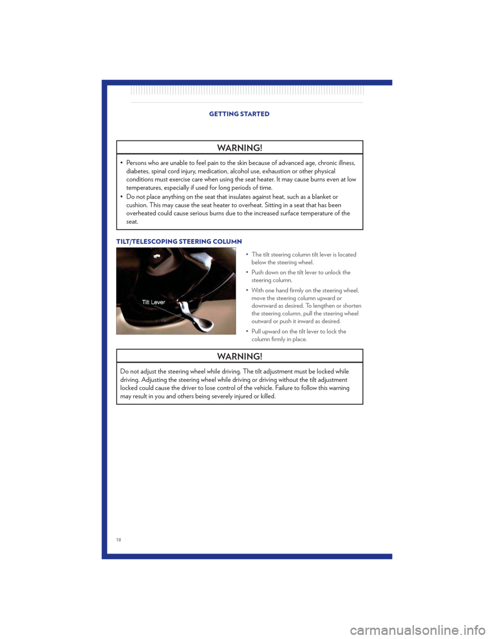
TILT/TELESCOPING STEERING COLUMN
• The tilt steering column tilt lever is locatedbelow the steering wheel.
• Push down on the tilt lever to unlock the steering column.
• With one hand firmly on the steering wheel, move the steering column upward or
downward as desired. To lengthen or shorten
the steering column, pull the steering wheel
outward or push it inward as desired.
• Pull upward on the tilt lever to lock the column firmly in place.
WARNING!
Do not adjust the steering wheel while driving. The tilt adjustment must be locked while
driving. Adjusting the steering wheel while driving or driving without the tilt adjustment
locked could cause the driver to lose control of the vehicle. Failure to follow this warning
may result in you and others being severely injured or killed.
GETTING STARTED
18
Page 24 of 100

Overhead (Halo) Light
• To activate the Halo lights, rotate the Halo switch control upward or downward to increase ordecrease the lighting.
SPEED CONTROL • The speed control switches are located onthe steering wheel.
Cruise ON/OFF
• Push the ON/OFF button to activate theSpeed Control.
• CRUISE READY
will appear on the
instrument cluster to indicate the Speed
Control is on.
• Push the ON/OFF button a second time to turn the system off.
Set
• With the Speed Control on, push and release the SET – button to set a desired speed.
Accel/Decel
• Once a speed is set, pushing the RES + button once or the SET – button once will increase or
decrease the set speed approximately 1 mph (2 km/h).
• Push and hold the RES + button to accelerate in 5mph (8 km/h) increments or push and hold the SET – button to decelerate in 5mph (8 km/h) increments; release the button to save the
new set speed.
Resume
• To resume a previously selected set speed in memory, push the RES + button and release.
Cancel
• Push the CANCEL button, or apply the brakes to cancel the set speed and maintain the setspeed memory.
• Push the ON/OFF button to turn the system off and erase the set speed memory.
OPERATING YOUR VEHICLE
22
Page 48 of 100
Changing The Volume
• Start a dialogue by pressing the Phone button, then adjust the volume during a normal
call.
• Use the radio ON/OFF VOLUME rotary knob to adjust the volume to a comfortable level while the Uconnect™ system is speaking. Please note the volume setting for Uconnect™ is
different than the audio system.
NOTE: To access the tutorial, press the Uconnect™ hard-key. After the BEEP, say “tutorial”.
Press any hard-key/button or touch the display (Touch-Screen radio) to cancel the tutorial.
WARNING!
• Any voice commanded system should be used only in safe driving conditions following local laws and phone use. All attention should be kept on the roadway ahead. Failure to
do so may result in a collision causing you and others to be severely injured or killed.
• In an emergency, to use Uconnect™ Phone, your mobile phone must be: • turned on,
• paired to Uconnect™ Phone,
• and have network coverage.
Uconnect™ VOICE COMMAND
• The Uconnect™ Voice Command system allows you to control your AM, FM radio, satelliteradio, disc player, Uconnect™ Phone, a memo recorder, and supported portable media devices.
• When you press the Voice Command button
located on the radio faceplate or
steering wheel, you will hear a beep. The beep is your signal to give a command. If you do not
say a command within a few seconds, the system will present you with a list of options. If you
ever wish to interrupt the system while it lists options, press the Voice Command
button
, listen for the BEEP, and say your command.
Voice Command for Text Messaging
• If equipped with Uconnect™ Voice Command, your Media Center 430N radio may be able to play incoming SMS messages through the vehicle sound system.
• It also allows you to respond by selecting from various pre-defined phrases.
• Not all phones are compatible with this feature. Refer to the phone compatibility list at www.chrysler.com/uconnect. Connected mobile phones must be bluetooth-compatible, and
paired with your radio.
Changing The Volume
• Start a dialogue by pressing the Voice Command button, then say a command (for
example, “tutorial”).
• Use the radio ON/OFF VOLUME rotary knob to adjust the volume to a comfortable level while the Voice Command system is speaking. The volume setting for Voice Command is
different than the audio system. ELECTRONICS
46
Page 49 of 100
• For vehicles equipped with Video Entertainment System (VES)™, refer to the Uconnect™ VoiceCommand section of the Uconnect™ User's Manual on the DVD for further details.
• For vehicles not equipped with VES™, refer to your vehicle Owner's Manual on the DVD for Uconnect™ Voice Command information.
NOTE: To access the tutorial, press the Voice Command button
. After the BEEP, say
“tutorial”. Press any hard-key/button or touch the display (Touch-Screen radio) to cancel the
tutorial.
WARNING!
Any voice commanded system should be used only in safe driving conditions following
local laws and phone use. All attention should be kept on the roadway ahead. Failure to do
so may result in a collision causing you and others to be severely injured or killed.
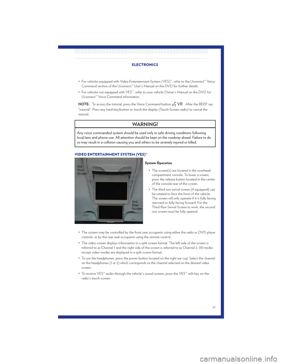
VIDEO ENTERTAINMENT SYSTEM (VES)™
System Operation
• The screen(s) are located in the overhead compartment console. To lower a screen,
press the release button located in the center
of the console rear of the screen.
• The third row swivel screen (if equipped) can be rotated to face the front of the vehicle.
The screen will only operate if it is fully facing
rearward or fully facing forward. For the
Third Row Swivel Screen to work, the second
row screen must be fully opened.
• The system may be controlled by the front seat occupants using either the radio or DVD player controls, or by the rear seat occupants using the remote control.
• The video screen displays information in a split screen format. The left side of the screen is referred to as Channel 1 and the right side of the screen is referred to as Channel 2. All modes
except video modes are displayed in a split screen format.
• To use the headphones, press the power button located on the right ear cup. Select the channel on the headphones (1 or 2) which corresponds to the channel selected on the desired video
screen.
• To receive VES™ audio through the vehicle's sound system, press the VES™ soft-key on the radio's touch-screen.
ELECTRONICS
47
Page 60 of 100

24-HOUR TOWING ASSISTANCE• Dial toll-free 1-800-521-2779 or 1-800-363-4869 for Canadian residents.
• Provide your name, vehicle identification number and license plate number.
• Provide your location, including telephone number, from which you are calling.
• Briefly describe the nature of the problem and answer a few simple questions.
• You will be given the name of the service provider and an estimated time of arrival. If you feelyou are in an “unsafe situation”, please let us know. With your consent, we will contact local
police or safety authorities.
INSTRUMENT CLUSTER WARNING LIGHTS
- Electronic Stability Control (ESC) Indicator Light
• If this indicator light flashes during acceleration, apply as little throttle as possible. While driving, ease up on the accelerator. Adapt your speed and driving to the prevailing road
conditions. To improve the vehicle's traction when starting off in deep snow, sand or gravel, it
may be desirable to switch the ESC system off.
- Tire Pressure Monitoring System (TPMS) Light
• Each tire, including the spare (if provided), should be checked monthly, when cold and inflatedto the inflation pressure recommended by the vehicle manufacturer on the vehicle placard or
tire inflation pressure label. (If your vehicle has tires of a different size than the size indicated on
the vehicle placard or tire inflation pressure label, you should determine the proper tire inflation
pressure for those tires.)
• As an added safety feature, your vehicle has been equipped with a Tire Pressure Monitoring System (TPMS) that illuminates a low tire pressure telltale when one or more of your tires is
significantly under-inflated. Accordingly, when the low tire pressure telltale illuminates, you
should stop and check your tires as soon as possible, and inflate them to the proper pressure.
Driving on a significantly under-inflated tire causes the tire to overheat and can lead to tire
failure. Under-inflation also reduces fuel efficiency and tire tread life, and may affect the
vehicle’s handling and stopping ability.
• IF THE LIGHT STARTS FLASHING INDICATING A LOW TIRE PRESSURE, ADJUST
THE AIR PRESSURE IN THE LOW TIRE TO THE AIR PRESSURE SHOWN ON THE
VEHICLE PLACARD OR TIRE INFLATION PRESSURE LABEL LOCATED ON THE
DRIVER'S DOOR. NOTE: AFTER INFLATION, THE VEHICLE MAY NEED TO BE
DRIVEN FOR 20 MINUTES BEFORE THE FLASHING LIGHT WILL TURN OFF.
• Please note that the TPMS is not a substitute for proper tire maintenance, and it is the driver’s responsibility to maintain correct tire pressure, even if under-inflation has not reached the level
to trigger illumination of the TPMS low tire pressure telltale.
• Your vehicle has also been equipped with a TPMS malfunction indicator to indicate when the system is not operating properly. The TPMS malfunction indicator is combined with the low tire
pressure telltale. When the system detects a malfunction, the telltale will flash for approximately
one minute and then remain continuously illuminated. This sequence will continue each time
the vehicle is restarted as long as the malfunction exists. WHAT TO DO IN EMERGENCIES
58
Page 85 of 100
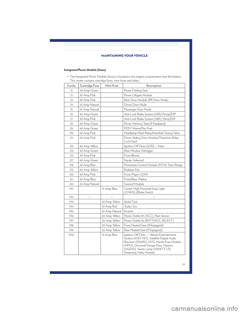
Integrated Power Module (fuses)
• The Integrated Power Module (fuses) is located in the engine compartment near the battery.This center contains cartridge fuses, mini-fuses and relays.
Cavity Cartridge Fuse Mini-Fuse Description
J1 40 Amp Green Power Folding Seat
J2 30 Amp Pink Power Liftgate Module
J3 30 Amp Pink Rear Door Module (RR Door Node)
J4 25 Amp Natural Driver Door Node
J5 25 Amp Natural Passenger Door Node
J6 40 Amp Green Anti-Lock Brake System (ABS) Pump/ESP
J7 30 Amp Pink Anti-Lock Brake System (ABS) Valve/ESP
J8 40 Amp Green Power Memory Seat (If Equipped)
J9 40 Amp Green PZEV Motor/Flex Fuel
J10 30 Amp Pink Headlamp Wash Relay/Manifold Tuning Valve
J11 30 Amp Pink Power Sliding Door Module/Thatchum Relay
Lock Feed
J13 60 Amp Yellow Ignition Off Draw (IOD) — Main
J14 40 Amp Green Rear Window Defogger
J15 30 Amp Pink Front Blower
J17 40 Amp Green Starter Solenoid
J18 20 Amp Blue Powertrain Control Module (PCM) Trans Range
J19 60 Amp Yellow Radiator Fan
J20 30 Amp Pink Front Wiper LO/HI
J21 20 Amp Blue Front/Rear Washer
J22 25 Amp Natural Sunroof Module
M1 15 Amp Blue Center High Mounted Stop Light
(CHMSL)/Brake Switch
M2 — — —
M3 20 Amp Yellow Spare Fuse
M4 10 Amp Red Trailer Tow
M5 25 Amp Natural Inverter
M6 20 Amp Yellow Power Outlet #1 (ACC), Rain Sensor
M7 20 Amp Yellow Power Outlet #2 (BATT/ACC SELECT)
M8 20 Amp Yellow Front Heated Seat (If Equipped)
M9 20 Amp Yellow Rear Heated Seat (If Equipped)
M10 15 Amp Blue Ignition Off Draw — Vehicle Entertainment
System (IOD-VES), Satellite Digital Audio
Receiver (SDARS), DVD, Hands-Free Module
(HFM), Universal Garage Door Opener
(UGDO), Vanity Lamp (VANITY LP),
Streaming Video Module
MAINTAINING YOUR VEHICLE
83
Page 87 of 100
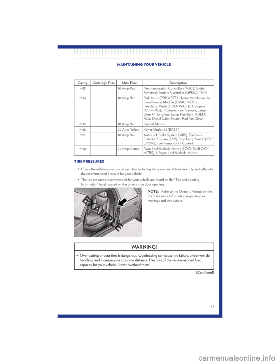
Cavity Cartridge Fuse Mini-FuseDescription
M33 10 Amp Red Next Generation Controller (NGC), Global
Powertrain Engine Controller (GPEC), TCM
M34 10 Amp Red Park Assist (PRK ASST), Heater Ventilation, Air
Conditioning Module (HVAC MOD),
Headlamp Wash (HDLP WASH), Compass
(COMPAS), IR Sensor, Rear Camera, Lamp
Door FT Drv/Pass, Lamp Flashlight, AHLM,
Relay Diesel Cabin Heater, Rad Fan Diesel
M35 10 Amp Red Heated Mirrors
M36 20 Amp Yellow Power Outlet #3 (BATT)
M37 10 Amp Red Anti-Lock Brake System (ABS), Electronic
Stability Program (ESP), Stop Lamp Switch (STP
LP SW), Fuel Pump Rly Hi Control
M38 25 Amp Natural Door Lock/Unlock Motors (LOCK/UNLOCK
MTRS), Liftgate Lock/Unlock Motors
TIRE PRESSURES • Check the inflation pressure of each tire, including the spare tire, at least monthly and inflate tothe recommended pressure for your vehicle.
• The tire pressures recommended for your vehicle are found on the “Tire and Loading Information” label located on the driver’s side door opening.
NOTE:Refer to the Owner's Manual on the
DVD for more information regarding tire
warnings and instructions.
WARNING!
• Overloading of your tires is dangerous. Overloading can cause tire failure, affect vehicle handling, and increase your stopping distance. Use tires of the recommended load
capacity for your vehicle . Never overload them.
(Continued)
MAINTAINING YOUR VEHICLE
85
Page 88 of 100
WARNING!(Continued)
• Improperly inflated tires are dangerous and can cause collisions. Under-inflation is theleading cause of tire failure and may result in severe cracking, component separation, or
“blow out”. Over-inflation reduces a tire’s ability to cushion shock. Objects on the road
and chuck holes can cause damage that results in tire failure. Unequal tire pressures can
cause steering problems. You could lose control of your vehicle. Over-inflated or
under-inflated tires can affect vehicle handling and can fail suddenly, resulting in loss of
vehicle control.
WHEEL AND WHEEL TRIM CARE
• All wheels and wheel trim, especially aluminum and chrome plated wheels, should be cleanedregularly with a mild soap and water to prevent corrosion.
• To remove heavy soil and/or excessive brake dust, use MOPAR® Wheel Cleaner or equivalent or select a non-abrasive, non-acidic cleaner.
CAUTION!
Do not use scouring pads, steel wool, a bristle brush, or metal polishes. Do not use oven
cleaner. These products may damage the wheel's protective finish. Avoid automatic car
washes that use acidic solutions or harsh brushes that may damage the wheel's protective
finish. Only MOPAR® Wheel Cleaner or equivalent is recommended.
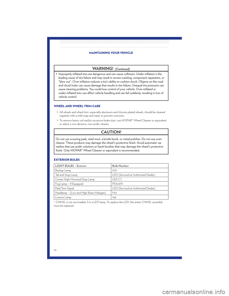
EXTERIOR BULBS
LIGHT BULBS – Exterior Bulb Number
Backup Lamp 3157
Tail and Stop Lamp LED (Serviced at Authorized Dealer)
Center High-Mounted Stop Lamp LED (*)
Fog Lamp – If Equipped PSX24W
Park/Turn Signal LED (Serviced at Authorized Dealer)
Headlamp – (Low and High Beam Halogen) H13
License Lamp 168
* CHMSL is not serviceable. It is a LED lamp. To replace the LED, the entire CHMSL assembly
must be replaced. MAINTAINING YOUR VEHICLE
86