light CHRYSLER TOWN AND COUNTRY 2012 5.G Owner's Manual
[x] Cancel search | Manufacturer: CHRYSLER, Model Year: 2012, Model line: TOWN AND COUNTRY, Model: CHRYSLER TOWN AND COUNTRY 2012 5.GPages: 132, PDF Size: 3.41 MB
Page 81 of 132

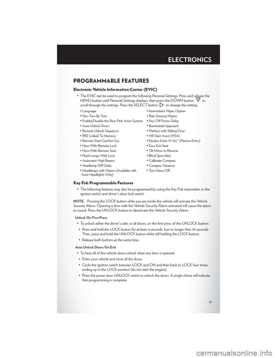
PROGRAMMABLE FEATURES
Electronic Vehicle Information Center (EVIC)
• The EVIC can be used to program the following Personal Settings. Press and release theMENU button until Personal Settings displays, then press the DOWN button
to
scroll through the settings. Press the SELECT button
to change the setting.
• Language • Intermittent Wiper Option
• Nav-Turn By Turn • Rain Sensing Wipers
• Enable/Disable the Rear Park Assist System • Key-Off Power Delay
• Auto Unlock Doors • Illuminated Approach
• Remote Unlock Sequence • Flashers with Sliding Door
• RKE Linked To Memory • Hill Start Assist (HSA)
• Remote Start Comfort Sys. • Keyless Enter-N-Go™ (Passive Entry)
• Horn With Remote Lock • Easy Exit Seat
• Horn With Remote Start • Tilt Mirror In Reverse
• Flash Lamps With Lock • Blind Spot Alert
• Automatic High Beams • Calibrate Compass
• Headlamp Off Delay • Compass Variance
• Headlamps with Wipers (Available with Auto Headlights Only) • Turn Menu Off
Key Fob Programmable Features
• The following features may also be programmed by using the Key Fob transmitter or the
ignition switch and driver's door lock switch.
NOTE:Pressing the LOCK button while you are inside the vehicle will activate the Vehicle
Security Alarm. Opening a door with the Vehicle Security Alarm activated will cause the alarm
to sound. Press the UNLOCK button to deactivate the Vehicle Security Alarm.
Unlock On First Press
• To unlock either the driver's side, or all doors, on the first press of the UNLOCK button:
• Press and hold the LOCK button for at least 4 seconds, but no longer than 10 seconds. Then, press and hold the UNLOCK button while still holding the LOCK button.
• Release both buttons at the same time.
Auto Unlock Doors On Exit
• To have all of the vehicle doors unlock when any door is opened: • Enter your vehicle and close all the doors.
• Cycle the ignition switch between LOCK and ON and then back to LOCK four times, ending up in the LOCK position (do not start the engine).
• Press the power door UNLOCK switch to unlock the doors. A single chime will indicate that programming is complete.
ELECTRONICS
77
Page 82 of 132

Sound Horn With Lock
• To turn the horn chirp on or off when the doors are locked:• Press the LOCK button for at least 4 seconds, but no longer than 10 seconds. Then, press the PANIC button while still holding the LOCK button.
• Release both buttons at the same time.
Flashing Lights With Lock
• The turn signal lights flashing, when the doors are locked or unlocked, feature can be turned on or off. To turn this feature on or off:
• Press and hold the UNLOCK button for at least 4 seconds, but no longer than 10 seconds. Then, press and hold the LOCK button while still holding the UNLOCK
button.
• Release both buttons at the same time.
UNIVERSAL GARAGE DOOR OPENER (HomeLink®)
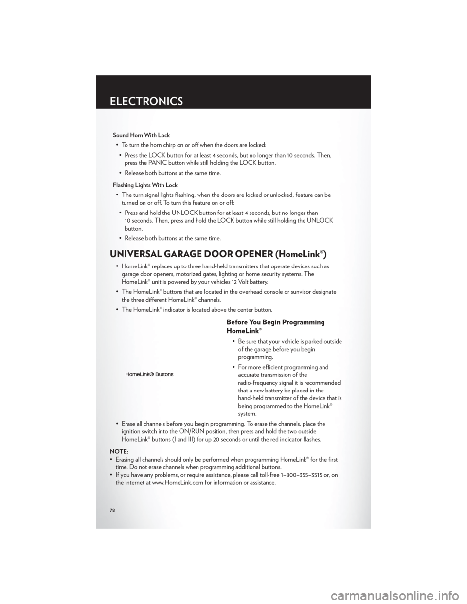
• HomeLink® replaces up to three hand-held transmitters that operate devices such as garage door openers, motorized gates, lighting or home security systems. The
HomeLink® unit is powered by your vehicles 12 Volt battery.
• The HomeLink® buttons that are located in the overhead console or sunvisor designate the three different HomeLink® channels.
• The HomeLink® indicator is located above the center button.
Before You Begin Programming
HomeLink®
• Be sure that your vehicle is parked outside of the garage before you begin
programming.
• For more efficient programming and accurate transmission of the
radio-frequency signal it is recommended
that a new battery be placed in the
hand-held transmitter of the device that is
being programmed to the HomeLink®
system.
• Erase all channels before you begin programming. To erase the channels, place the ignition switch into the ON/RUN position, then press and hold the two outside
HomeLink® buttons (I and III) for up 20 seconds or until the red indicator flashes.
NOTE:
• Erasing all channels should only be performed when programming HomeLink® for the firsttime. Do not erase channels when programming additional buttons.
• If you have any problems, or require assistance, please call toll-free 1–800–355–3515 or, on the Internet at www.HomeLink.com for information or assistance.
ELECTRONICS
78
Page 83 of 132

Programming A Rolling Code
• For programming Garage Door Openers that were manufactured after 1995. TheseGarage Door Openers can be identified by the “LEARN” or “TRAIN” button located
where the hanging antenna is attached to the Garage Door Opener. It is NOT the button
that is normally used to open and close the door. The name and color of the button may
vary by manufacturer.
• Place the ignition switch into the ON/RUN position.
• Place the hand-held transmitter 1 to 3 in (3 to 8 cm) away from the HomeLink® button you wish to program while keeping the HomeLink® indicator light in view.
• Simultaneously press and hold both the HomeLink® button you want to program and the hand-held transmitter button.
• Continue to hold both buttons and observe the indicator light. The Homelink® indicator will flash slowly and then rapidly after Homelink® has received the frequency signal from
the hand-held transmitter. Release both buttons after the indicator light changes from
slow to rapid.
• At the garage door opener motor (in the garage), locate the “LEARN” or “TRAINING” button. This can usually be found where the hanging antenna wire is attached to the
garage door opener motor. Firmly press and release the “LEARN” or “TRAINING”
button.
NOTE:You have 30 seconds in which to initiate the next step after the LEARN button has
been pressed.
• Return to the vehicle and press the programmed HomeLink® button twice (holding thebutton for two seconds each time). If the device is plugged in and activates, programming
is complete.
NOTE:If the device does not activate, press the button a third time (for two seconds) to
complete the training.
• To program the remaining two HomeLink® buttons, repeat each step for each remainingbutton. DO NOT erase the channels.
Programming A Non-Rolling Code
• For programming Garage Door Openers manufactured before 1995.
• Turn the ignition switch to the ON/RUN position.
• Place the hand-held transmitter 1 to 3 in (3 to 8 cm) away from the HomeLink® buttonyou wish to program while keeping the HomeLink® indicator light in view.
• Simultaneously press and hold both the HomeLink® button you want to program and the hand-held transmitter button.
• Continue to hold both buttons and observe the indicator light. The Homelink® indicator will flash slowly and then rapidly after Homelink® has received the frequency signal from
the hand-held transmitter. Release both buttons after the indicator light changes from
slow to rapid.
• Press and hold the programmed HomeLink® button and observe the indicator light.
ELECTRONICS
79
Page 84 of 132

NOTE:
• If the indicator light stays on constantly, programming is complete and the garage door (ordevice) should activate when the HomeLink® button is pressed.
• To program the two remaining HomeLink® buttons, repeat each step for each remaining button. DO NOT erase the channels.
Using HomeLink®
• To operate, press and release the programmed HomeLink® button. Activation will nowoccur for the programmed device (i.e., garage door opener, gate operator, security
system, entry door lock, home/office lighting, etc.,). The hand-held transmitter of the
device may also be used at any time.
WARNING!
• Your motorized door or gate will open and close while you are programming the universaltransceiver. Do not program the transceiver if people or pets are in the path of the door
or gate.
• Do not run your vehicle in a closed garage or confined area while programming the transceiver. Exhaust gas from your vehicle contains Carbon Monoxide (CO) which is
odorless and colorless. Carbon Monoxide is poisonous when inhaled and can cause you
and others to be severely injured or killed.
POWER INVERTER
• There is a 115 Volt, 150 Watt powerinverter outlet located on the left rear trim
panel immediately behind the second row
left passenger seat. This outlet can power
cellular phones, electronics and other low
power devices requiring power up to 150
Watts.
• Press the switch located in the center of the instrument panel to turn the power to
the outlet on.
• Press the switch again to turn the power off.
• The status indicator of the AC power inverter indicates whether the inverter is producing AC power.
NOTE:The power inverter is designed with built-in overload protection. If the power rating
of 150 Watts is exceeded, the power inverter will automatically shut down. Once the electrical
device has been removed from the outlet, the inverter should automatically reset. If the power
rating exceeds approximately 170 Watts, the power inverter may have to be reset manually. To
reset the inverter manually, unplug the device and plug it in again. To avoid overloading the
circuit, check the power ratings on electrical devices prior to using the inverter.
ELECTRONICS
80
Page 85 of 132

WARNING!
To Avoid Serious Injury or Death: Do not use a three-prong adaptor. Do not insert any
objects into the receptacles. Do not touch with wet hands. Close the lid when not in use. If
this outlet is mishandled, it may cause an electric shock and failure.
POWER OUTLETS
• Two 12 Volt (13 Amp) power outlets arelocated on the lower instrument panel,
below the open storage bin. The
driver-side power outlet is controlled by
the ignition switch and the passenger-side
power outlet is connected directly to the
battery. The driver-side power outlet will
also operate a conventional cigar lighter
unit (if equipped with an optional
Smoker's Package).
• One outlet in the removable floor console (if equipped) shares a fuse with the lower outlet in the instrument panel and is also connected to the battery. Do not exceed a
maximum power of 160 Watts (13 Amps) shared between the lower panel outlet and the
removable floor console outlet.
• On vehicles equipped with the Super Console the power outlets are located under the retractable cover. To access the power outlets push down on the cover and slide it toward
the instrument panel.
• The outlet in the rear quarter panel near the liftgate and the upper outlet in the instrument panel are both controlled by the ignition switch. Each of these outlets can
support 160 Watts (13 Amps). Do not exceed 160 Watts (13 Amps) for each of these
outlets.
ELECTRONICS
81
Page 90 of 132

24-HOUR TOWING ASSISTANCE
• Dial toll-free 1-800-521-2779 or 1-800-363-4869 for Canadian residents.
• Provide your name, vehicle identification number and license plate number.
• Provide your location, including telephone number, from which you are calling.
• Briefly describe the nature of the problem and answer a few simple questions.
• You will be given the name of the service provider and an estimated time of arrival. If youfeel you are in an “unsafe situation”, please let us know. With your consent, we will contact
local police or safety authorities.
INSTRUMENT CLUSTER WARNING LIGHTS
- Electronic Stability Control (ESC) Indicator Light
• If this indicator light flashes during acceleration, apply as little throttle as possible. Whiledriving, ease up on the accelerator. Adapt your speed and driving to the prevailing road
conditions. To improve the vehicle's traction when starting off in deep snow, sand or
gravel, it may be desirable to switch the ESC system off.
- Tire Pressure Monitoring System (TPMS) Light
• Each tire, including the spare (if provided), should be checked monthly, when cold andinflated to the inflation pressure recommended by the vehicle manufacturer on the
vehicle placard or tire inflation pressure label. (If your vehicle has tires of a different size
than the size indicated on the vehicle placard or tire inflation pressure label, you should
determine the proper tire inflation pressure for those tires.)
• As an added safety feature, your vehicle has been equipped with a Tire Pressure Monitoring System (TPMS) that illuminates a low tire pressure telltale when one or more
of your tires is significantly under-inflated. Accordingly, when the low tire pressure telltale
illuminates, you should stop and check your tires as soon as possible, and inflate them to
the proper pressure. Driving on a significantly under-inflated tire causes the tire to
overheat and can lead to tire failure. Under-inflation also reduces fuel efficiency and tire
tread life, and may affect the vehicle’s handling and stopping ability.
• IF THE LIGHT STARTS FLASHING INDICATING A LOW TIRE PRESSURE,
ADJUST THE AIR PRESSURE IN THE LOW TIRE TO THE AIR PRESSURE
SHOWN ON THE VEHICLE PLACARD OR TIRE INFLATION PRESSURE
LABEL LOCATED ON THE DRIVER'S DOOR. NOTE: AFTER INFLATION,
THE VEHICLE MAY NEED TO BE DRIVEN FOR 20 MINUTES BEFORE THE
FLASHING LIGHT WILL TURN OFF.
• Please note that the TPMS is not a substitute for proper tire maintenance, and it is the driver’s responsibility to maintain correct tire pressure, even if under-inflation has not
reached the level to trigger illumination of the TPMS low tire pressure telltale.
WHAT TO DO IN EMERGENCIES
86
Page 91 of 132

• Your vehicle has also been equipped with a TPMS malfunction indicator to indicate whenthe system is not operating properly. The TPMS malfunction indicator is combined with
the low tire pressure telltale. When the system detects a malfunction, the telltale will flash
for approximately one minute and then remain continuously illuminated. This sequence
will continue each time the vehicle is restarted as long as the malfunction exists.
• When the malfunction indicator is illuminated, the system may not be able to detect or signal low tire pressure as intended. TPMS malfunctions may occur for a variety of
reasons, including the installation of replacement or alternate tires or wheels on the
vehicle that prevent the TPMS from functioning properly. Always check the TPMS
malfunction telltale after replacing one or more tires or wheels on your vehicle, to ensure
that the replacement or alternate tires and wheels allow the TPMS to continue to function
properly.
NOTE:Tire pressures change by approximately 1 psi (7 kPa) per 12° F (7° C) of air
temperature change. Keep this in mind when checking tire pressure inside a garage, especially
in the Winter. Example: If garage temperature is 68°F (20°C) and the outside temperature is
32°F (0°C), then the cold tire inflation pressure should be increased by 3 psi (21 kPa), which
equals 1 psi (7 kPa) for every 12°F (7°C) for this outside temperature condition.
CAUTION!
The TPMS has been optimized for the original equipment tires and wheels. TPMS
pressures and warning have been established for the tire size equipped on your vehicle.
Undesirable system operation or sensor damage may result when using replacement
equipment that is not of the same size, type, and/or style. Aftermarket wheels can cause
sensor damage. Do not use tire sealant from a can, or balance beads if your vehicle is
equipped with a TPMS, as damage to the sensors may result.
- Engine Temperature Warning Light
• This light warns of an overheated engine condition.
• If the light turns on or flashes continuously while driving, safely pull over and stop the vehicle. If the A/C system is on, turn it off. Also, shift the transmission into NEUTRAL
and idle the vehicle. If the temperature reading does not return to normal, turn the engine
off immediately and call for service.
• We recommend that you do not operate the vehicle or engine damage will occur. Have the vehicle serviced immediately.
WARNING!
A hot engine cooling system is dangerous. You or others could be badly burned by steam
or boiling coolant. You may want to call an authorized service center for service if your
vehicle overheats.
WHAT TO DO IN EMERGENCIES
87
Page 92 of 132

BRAKE- Brake Warning Light
• The Brake Warning light illuminates when there is either a system malfunction or theparking brake is applied. If the light is on and the parking brake is not applied, it indicates
a possible brake hydraulic malfunction, brake booster problem or an Anti-Lock Brake
System problem.
• Please have your vehicle serviced immediately.
WARNING!
Driving a vehicle with the red brake light on is dangerous. Part of the brake system may
have failed. It will take longer to stop the vehicle. You could have a collision. Have the
vehicle checked immediately.
- Malfunction Indicator Light (MIL)
• Certain conditions, such as a loose or missing gas cap, poor fuel quality, etc., may illuminate the MIL after engine start. The vehicle should be serviced if the light stays on
through several typical driving cycles. In most situations, the vehicle will drive normally
and not require towing.
• If the MIL flashes when the engine is running, serious conditions may exist that could lead to immediate loss of power or severe catalytic converter damage. We recommend you do
not operate the vehicle. Have the vehicle serviced immediately.
- Electronic Stability Control (ESC) Indicator Light/Brake Assist System
(BAS) Warning Light
• If the ESC/BAS warning light comes on continuously with the engine running, a malfunction has been detected.
• If this light remains on after several ignition cy cles, and the vehicle has been driven several
miles (kilometers) at speeds greater than 30 mph (48 km/h), we recommend you drive to
the nearest service center and have the vehicle serviced immediately.
- Charging System Light
• This light shows the status of the electrical charging system. If the charging system light remains on, it means that the vehicle is experiencing a problem with the charging system.
• We recommend you do not continue driving if the charging system light is on. Have the vehicle serviced immediately.
- Oil Pressure Warning Light
• This light indicates low engine oil pressure. If the light turns on while driving, stop thevehicle and shut off the engine as soon as possible. A chime will sound for four minutes
when this light turns on.
• We recommend you do not operate the vehicle or engine damage will occur. Have the vehicle serviced immediately.
WHAT TO DO IN EMERGENCIES
88
Page 93 of 132

- Anti-Lock Brake (ABS) Light
• This light monitors the Anti-Lock Brake System (ABS).
• If the light is not on during starting, stays on, or turns on while driving, we recommendyou drive to the nearest service center and have the vehicle serviced immediately.
- Electronic Throttle Control (ETC) Light
• This light informs you of a problem with the Electronic Throttle Control (ETC) system.
• If a problem is detected, the light will come on while the engine is running. Cycle theignition when the vehicle has completely stopped and the shift lever is placed in the
PARK position; the light should turn off.
• If the light remains lit with the engine running, your vehicle will usually be drivable; however, see an authorized service center immediately. If the light is flashing when the
engine is running, immediate service is required and you may experience reduced
performance, an elevated/rough idle or engine stall and your vehicle may require towing.
- Air Bag Warning Light
• If the light is not on during starting, stays on, or turns on while driving, have the vehicleserviced by an authorized service center immediately.
Fuel Cap/Loose Gas Cap Message
• If a “gas cap” message (shown as gASCAP) appears, tighten the gas cap until a “clicking”sound is heard.
• Press the odometer reset button to turn the message off.
• If the message continues to appear for more than three days after tightening the gas cap, see your authorized service center.
Oil Change Indicator
Message
• If an “oil change” message (shown as CHAnGE OIL) appears and a single chime sounds,it is time for your next required oil change.
Resetting The Light After Servicing
Vehicles Equipped With Keyless Enter-N-Go™
• Without pressing the brake pedal, push the ENGINE START/STOP button and cycle theignition to the ON/RUN position (Do not start the engine.)
• Fully depress the accelerator pedal, slowly, three times within 10 seconds.
• Without pressing the brake pedal, push the ENGINE START/STOP button once to return the ignition to the OFF/LOCK position.
Vehicles Not Equipped With Keyless Enter-N-Go™
• Turn the ignition switch to the ON/RUN position (Do not start the engine.)
• Fully depress the accelerator pedal, slowly, three times within 10 seconds.
• Turn the ignition switch to the OFF/LOCK position.
WHAT TO DO IN EMERGENCIES
89
Page 101 of 132

NOTE:In some situations the jack may need
to be placed on its side in order to be pushed
under the vehicle. Return the jack to its correct
orientation once it is under the vehicle.
3. Place the wrench on the jack screw and turn to the right until the jack head is
properly engaged in the described
location. Do not raise the vehicle until
you are sure the jack is securely
engaged.
4. Raise the vehicle by turning the jack screw to the right, using the swivel wrench. Raise the vehicle only until the tire just clears the surface and enough clearance is obtained to
install the spare tire. Minimum tire lift provides maximum stability.
5. Remove the wheel lug nuts, for vehicles with wheel covers, remove the cover from the wheel by hand. Do not pry the wheel cover off. Then pull the wheel off the hub.
6. Install the compact spare tire. Lightly tighten the lug nuts.
NOTE:
• Do not install the wheel cover on the compact spare.
• Do not use a hammer or force to install the wheel covers.
7. Lower the vehicle by turning the jack screw to the left.
8. Finish tightening the lug nuts. Push down on the wrench while at the end of the handle for increased leverage. Tighten the lug nuts in a star pattern until each nut has been
tightened twice. The correct wheel nut tightness is 102 ft lbs (138 N·m). If in doubt about
the correct tightness, have them checked with a torque wrench by your authorized dealer
or at a service station.
9. Lower the jack to its fully-closed position.
10. Place the deflated (flat) tire and compact spare tire cover assembly in the rear cargo area. Do not stow the deflated tire in the spare tire location.
Have the full-sized tire
repaired or replaced, as soon as possible.
11. Stow the cable and wheel spacer before driving the vehicle. Reassemble the winch handle extensions to form a “T” and fit the winch T-handle over the drive nut. Rotate the
nut to the right until the winch mechanism clicks at least three times.
WHAT TO DO IN EMERGENCIES
97