center console CHRYSLER TOWN AND COUNTRY 2012 5.G User Guide
[x] Cancel search | Manufacturer: CHRYSLER, Model Year: 2012, Model line: TOWN AND COUNTRY, Model: CHRYSLER TOWN AND COUNTRY 2012 5.GPages: 132, PDF Size: 3.41 MB
Page 78 of 132

Bluetooth® STREAMING AUDIO
• If equipped with Uconnect™ VoiceCommand, your Bluetooth-equipped
iPod® devices, cell phones or other media
players, may also be able to stream music
to your vehicle's speakers. Your connected
device must be Bluetooth-compatible,
and paired with your Media Center radio
(see Uconnect™ Phone for pairing
instructions). Non-Touch-Screen Radios:
Press the “AUX” button on the radio faceplate until "BT" or “Audio Streaming” is
displayed on the radio screen. Touch-Screen-Radios: Press the “RADIO/MEDIA” or
“MEDIA” hard-key and then touch the “AUX” soft-key tab.
VIDEO ENTERTAINMENT SYSTEM (VES)™
System Operation
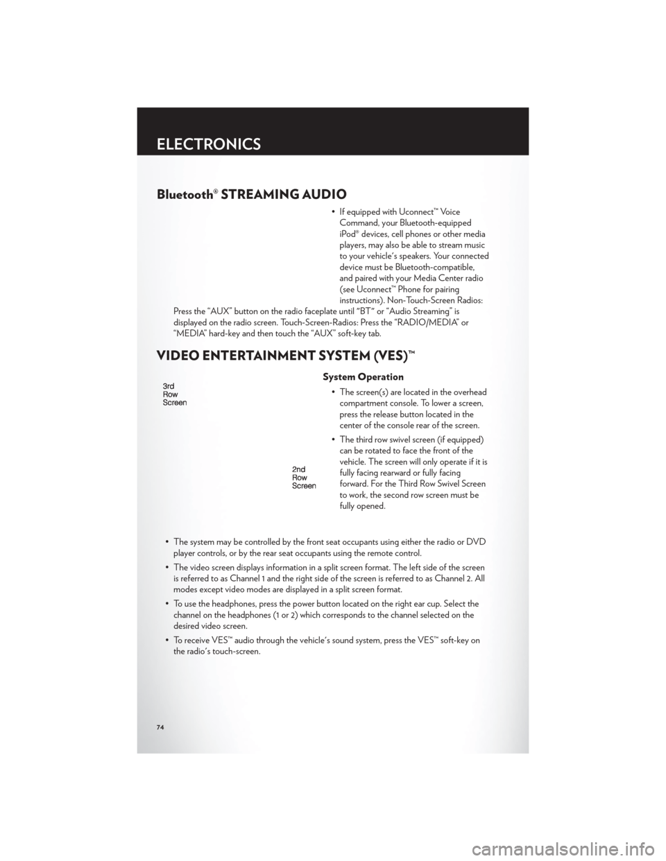
• The screen(s) are located in the overhead compartment console. To lower a screen,
press the release button located in the
center of the console rear of the screen.
• The third row swivel screen (if equipped) can be rotated to face the front of the
vehicle. The screen will only operate if it is
fully facing rearward or fully facing
forward. For the Third Row Swivel Screen
to work, the second row screen must be
fully opened.
• The system may be controlled by the front seat occupants using either the radio or DVD player controls, or by the rear seat occupants using the remote control.
• The video screen displays information in a split screen format. The left side of the screen is referred to as Channel 1 and the right side of the screen is referred to as Channel 2. All
modes except video modes are displayed in a split screen format.
• To use the headphones, press the power button located on the right ear cup. Select the channel on the headphones (1 or 2) which corresponds to the channel selected on the
desired video screen.
• To receive VES™ audio through the vehicle's sound system, press the VES™ soft-key on the radio's touch-screen.
ELECTRONICS
74
Page 82 of 132

Sound Horn With Lock
• To turn the horn chirp on or off when the doors are locked:• Press the LOCK button for at least 4 seconds, but no longer than 10 seconds. Then, press the PANIC button while still holding the LOCK button.
• Release both buttons at the same time.
Flashing Lights With Lock
• The turn signal lights flashing, when the doors are locked or unlocked, feature can be turned on or off. To turn this feature on or off:
• Press and hold the UNLOCK button for at least 4 seconds, but no longer than 10 seconds. Then, press and hold the LOCK button while still holding the UNLOCK
button.
• Release both buttons at the same time.
UNIVERSAL GARAGE DOOR OPENER (HomeLink®)
• HomeLink® replaces up to three hand-held transmitters that operate devices such as garage door openers, motorized gates, lighting or home security systems. The
HomeLink® unit is powered by your vehicles 12 Volt battery.
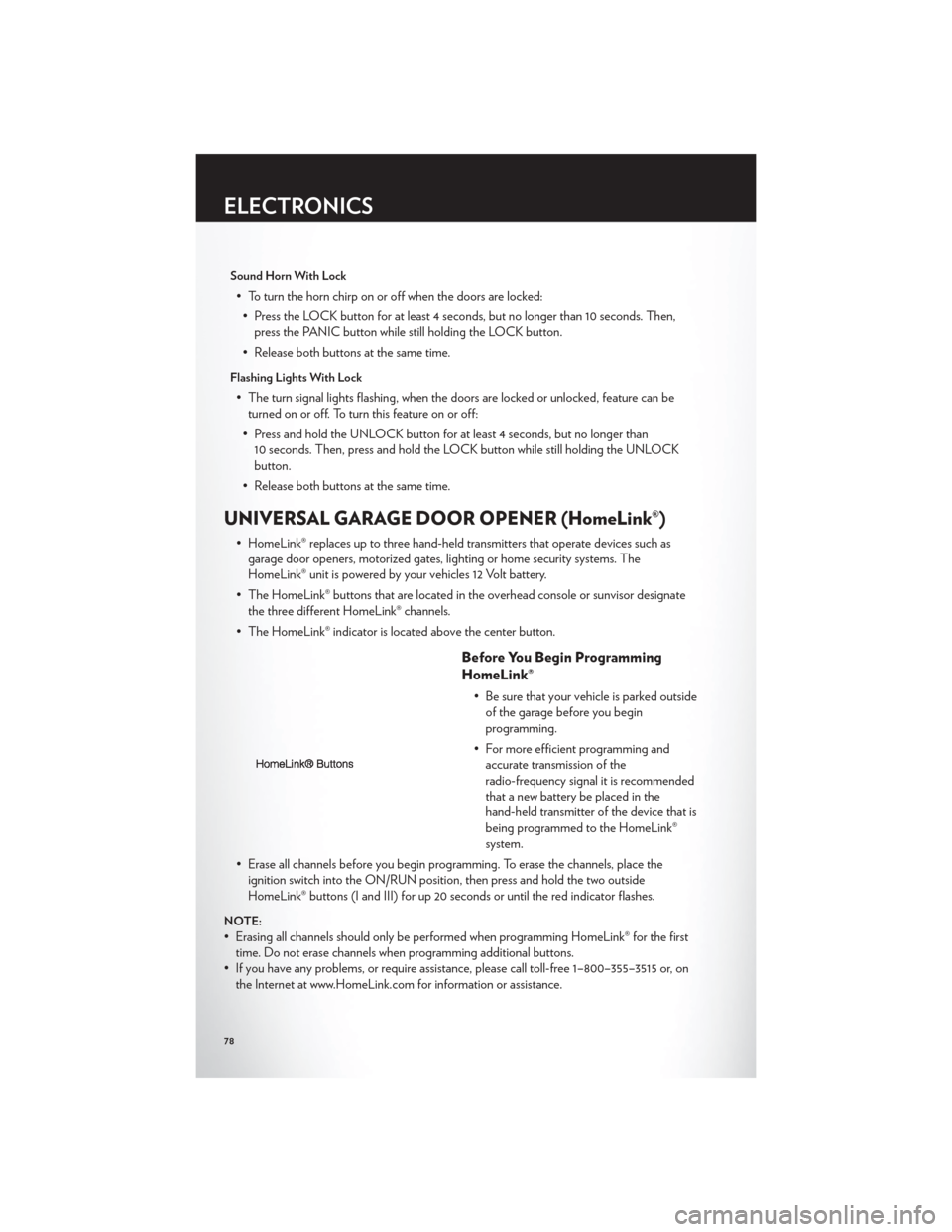
• The HomeLink® buttons that are located in the overhead console or sunvisor designate the three different HomeLink® channels.
• The HomeLink® indicator is located above the center button.
Before You Begin Programming
HomeLink®
• Be sure that your vehicle is parked outside of the garage before you begin
programming.
• For more efficient programming and accurate transmission of the
radio-frequency signal it is recommended
that a new battery be placed in the
hand-held transmitter of the device that is
being programmed to the HomeLink®
system.
• Erase all channels before you begin programming. To erase the channels, place the ignition switch into the ON/RUN position, then press and hold the two outside
HomeLink® buttons (I and III) for up 20 seconds or until the red indicator flashes.
NOTE:
• Erasing all channels should only be performed when programming HomeLink® for the firsttime. Do not erase channels when programming additional buttons.
• If you have any problems, or require assistance, please call toll-free 1–800–355–3515 or, on the Internet at www.HomeLink.com for information or assistance.
ELECTRONICS
78
Page 95 of 132

JACKING AND TIRE CHANGING
Jack Location
• The jack, jack handle and winch handle tools are stowed behind the rear left side trimpanel in the rear cargo area. Turn the two cover latches to release the cover.
• Remove the pouch containing the scissorsjack, jack handle, and tools.
Spare Tire Removal
• The spare tire is stowed inside a protective cover located under the center of the vehiclebetween the front doors by means of a cable winch mechanism. The “spare tire drive” nut
is located on the floor, under a plastic cap at the front of the floor console or under front
super console forward bin liner.
To Access Spare Tire Winch Drive Nut
• To access the spare tire winch drive nut and lower the spare tire, you will need to refer toone of the following center console configurations.
Super Console
• For vehicles equipped with the Super Console, the spare tire winch assembly drive nut islocated beneath the console.
1. Pull the lower drawer out from the rear ofthe floor console.
WHAT TO DO IN EMERGENCIES
91
Page 96 of 132

2. Open the front drawer to expose thestorage compartment.
3. Remove the liner from the console's storage compartment to access the spare
tire winch drive nut.
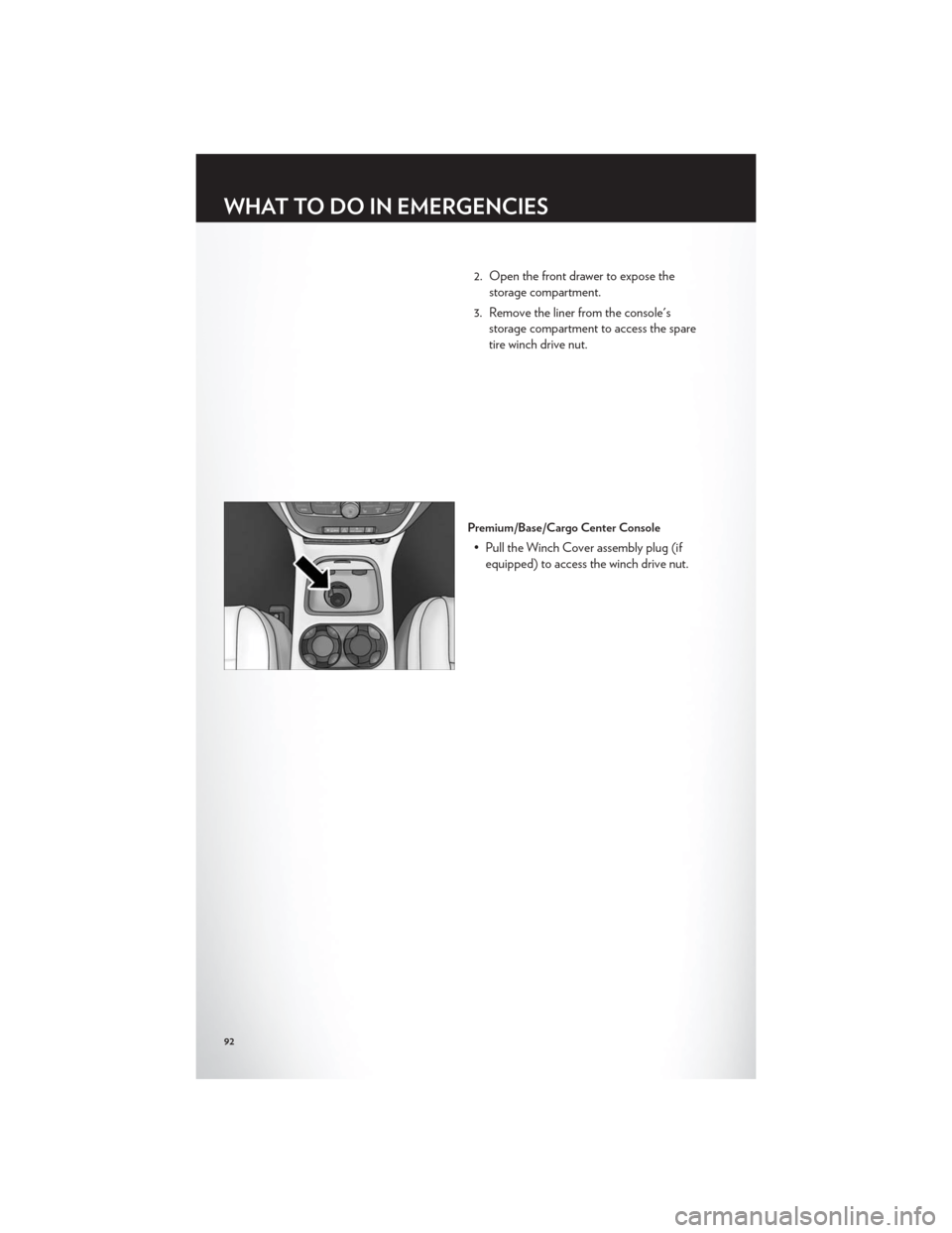
Premium/Base/Cargo Center Console
• Pull the Winch Cover assembly plug (ifequipped) to access the winch drive nut.
WHAT TO DO IN EMERGENCIES
92
Page 98 of 132

Spare Tire Removal Instructions
• The spare tire is located under the vehicle beneath the center console area.1. Assemble the spare tire tools into aT-handle and place the square end over
the spare tire winch drive nut.
2. Rotate the nut to the left until the winch mechanism stops turning freely. This will
allow enough slack in the cable to allow
you to pull the spare tire out from
underneath the vehicle.
3. Assemble the winch handle extensions to form the spare tire hook, and pull the
spare tire from under the vehicle.
NOTE:If either front tire is flat it may be
necessary to jack up the vehicle to remove
the compact spare tire/cover assembly from
under the vehicle.
4. Stand the tire/cover assembly upright and remove the wheel spacer by
squeezing the winch retaining tabs
together. Push the retainer through the
spare tire to release it from the wheel.
WHAT TO DO IN EMERGENCIES
94