sensor CHRYSLER TOWN AND COUNTRY 2013 5.G User Guide
[x] Cancel search | Manufacturer: CHRYSLER, Model Year: 2013, Model line: TOWN AND COUNTRY, Model: CHRYSLER TOWN AND COUNTRY 2013 5.GPages: 140, PDF Size: 4.18 MB
Page 40 of 140

PARKSENSE® REAR PARK ASSIST
• If an object is detected behind the rear bumper while the vehicle is in REVERSE, a warning willdisplay in the instrument cluster and a tone will sound, (closer the object the faster the tone)
that changes speed depending on the distance of the object from the bumper, will sound.
• When the Instrument Cluster reads either “Clean Sensor” or “Blinded”, clean off the bumper sensors to see if the condition is corrected.
PARKVIEW® REAR BACK-UP CAMERA
• You can see an on-screen image of the rear of your vehicle whenever the shift lever is put intoREVERSE. The ParkView® Rear Back-Up Camera image will be displayed on the radio display
screen, located on the center stack of the instrument panel.
• If the radio display screen appears foggy, clean the camera lens located on the liftgate.
WARNING!
Drivers must be careful when backing up; even when using the ParkView® Rear Back-Up
Camera. Always check carefully behind your vehicle, and be sure to check for pedestrians,
animals, other vehicles, obstructions, or blind spots before backing up. You must continue to
pay attention while backing up. Failure to do so can result in serious injury or death.
BLIND SPOT MONITORING WITH REAR
CROSS PATH
• The Blind Spot Monitoring (BSM) system uses two radar-based sensors, located inside the rear bumper fascia, to detect Highway licensable vehicles (automobiles, trucks, motorcycles
etc.) that enter the blind spot zones from the rear/front/side of the vehicle.
• The Blind Spot Monitoring (BSM) system warning light, located in the outside mirrors, will illuminate if a vehicle moves into a blind spot zone.
• The BSM system can also be configured to sound an audible (chime) alert and mute the radio to notify you of objects that have entered the detection zones.
• Refer to your Owner's Manual on the DVD for further details.
OPERATING YOUR VEHICLE
38
Page 94 of 140

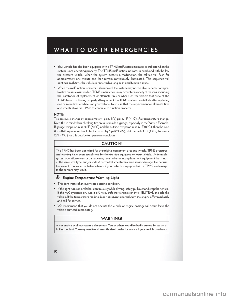
• Your vehicle has also been equipped with a TPMS malfunction indicator to indicate when thesystem is not operating properly. The TPMS malfunction indicator is combined with the low
tire pressure telltale. When the system detects a malfunction, the telltale will flash for
approximately one minute and then remain continuously illuminated. This sequence will
continue each time the vehicle is restarted as long as the malfunction exists.
• When the malfunction indicator is illuminated, the system may not be able to detect or signal low tire pressure as intended. TPMS malfunctions may occur for a variety of reasons, including
the installation of replacement or alternate tires or wheels on the vehicle that prevent the
TPMS from functioning properly. Always check the TPMS malfunction telltale after replacing
one or more tires or wheels on your vehicle, to ensure that the replacement or alternate tires
and wheels allow the TPMS to continue to function properly.
NOTE:
Tire pressures change by approximately 1 psi (7 kPa) per 12° F (7° C) of air temperature change.
Keep this in mind when checking tire pressure inside a garage, especially in the Winter. Example:
If garage temperature is 68°F (20°C) and the outside temperature is 32°F (0°C), then the cold
tire inflation pressure should be increased by 3 psi (21 kPa), which equals 1 psi (7 kPa) for every
12°F (7°C) for this outside temperature condition.
CAUTION!
The TPMS has been optimized for the original equipment tires and wheels. TPMS pressures
and warning have been established for the tire size equipped on your vehicle. Undesirable
system operation or sensor damage may result when using replacement equipment that is not
of the same size, type, and/or style. Aftermarket wheels can cause sensor damage. Do not use
tire sealant from a can, or balance beads if your vehicle is equipped with a TPMS, as damage
to the sensors may result.
- Engine Temperature Warning Light
• This light warns of an overheated engine condition.
• If the light turns on or flashes continuously while driving, safely pull over and stop the vehicle. If the A/C system is on, turn it off. Also, shift the transmission into NEUTRAL and idle the
vehicle. If the temperature reading does not return to normal, turn the engine off immediately
and call for service.
• We recommend that you do not operate the vehicle or engine damage will occur. Have the vehicle serviced immediately.
WARNING!
A hot engine cooling system is dangerous. You or others could be badly burned by steam or
boiling coolant. You may want to call an authorized dealer for service if your vehicle overheats.
WHAT TO DO IN EMERGENCIES
92
Page 122 of 140

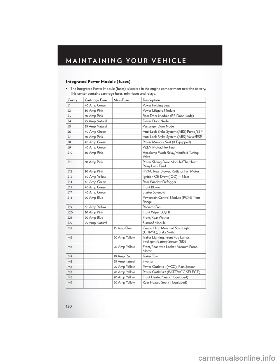
Integrated Power Module (fuses)
• The Integrated Power Module (fuses) is located in the engine compartment near the battery.This center contains cartridge fuses, mini-fuses and relays.
Cavity Cartridge Fuse Mini-Fuse Description
J1 40 Amp Green Power Folding Seat
J2 30 Amp Pink Power Liftgate Module
J3 30 Amp Pink Rear Door Module (RR Door Node)
J4 25 Amp Natural Driver Door Node
J5 25 Amp Natural Passenger Door Node
J6 40 Amp Green Anti-Lock Brake System (ABS) Pump/ESP
J7 30 Amp Pink Anti-Lock Brake System (ABS) Valve/ESP
J8 40 Amp Green Power Memory Seat (If Equipped)
J9 40 Amp Green PZEV Motor/Flex Fuel
J10 30 Amp Pink Headlamp Wash Relay/Manifold Tuning
Valve
J11 30 Amp Pink Power Sliding Door Module/Thatchum
Relay Lock Feed
J12 30 Amp Pink HVAC Rear Blower, Radiator Fan Motor
J13 60 Amp Yellow Ignition Off Draw (IOD) — Main
J14 40 Amp Green Rear Window Defogger
J15 40 Amp Green Front Blower
J17 40 Amp Green Starter Solenoid
J18 20 Amp Blue Powertrain Control Module (PCM) Trans
Range
J19 60 Amp Yellow Radiator Fan
J20 30 Amp Pink Front Wiper LO/HI
J21 20 Amp Blue Front/Rear Washer
J22 25 Amp Natural Sunroof Module
M1 15 Amp Blue Center High Mounted Stop Light
(CHMSL)/Brake Switch
M2 20 Amp Yellow Trailer Lighting, Front Fog Lamps,
Intelligent Battery Sensor (IBS)
M3 20 Amp Yellow Front/Rear Axle Locker, Vacuum Pump
Motor
M4 10 Amp Red Trailer Tow
M5 25 Amp natural Inverter
M6 20 Amp Yellow Power Outlet #1 (ACC), Rain Sensor
M7 20 Amp Yellow Power Outlet #2 (BATT/ACC SELECT)
M8 20 Amp Yellow Front Heated Seat (If Equipped)
M9 20 Amp Yellow Rear Heated Seat (If Equipped)
MAINTAINING YOUR VEHICLE
120
Page 124 of 140

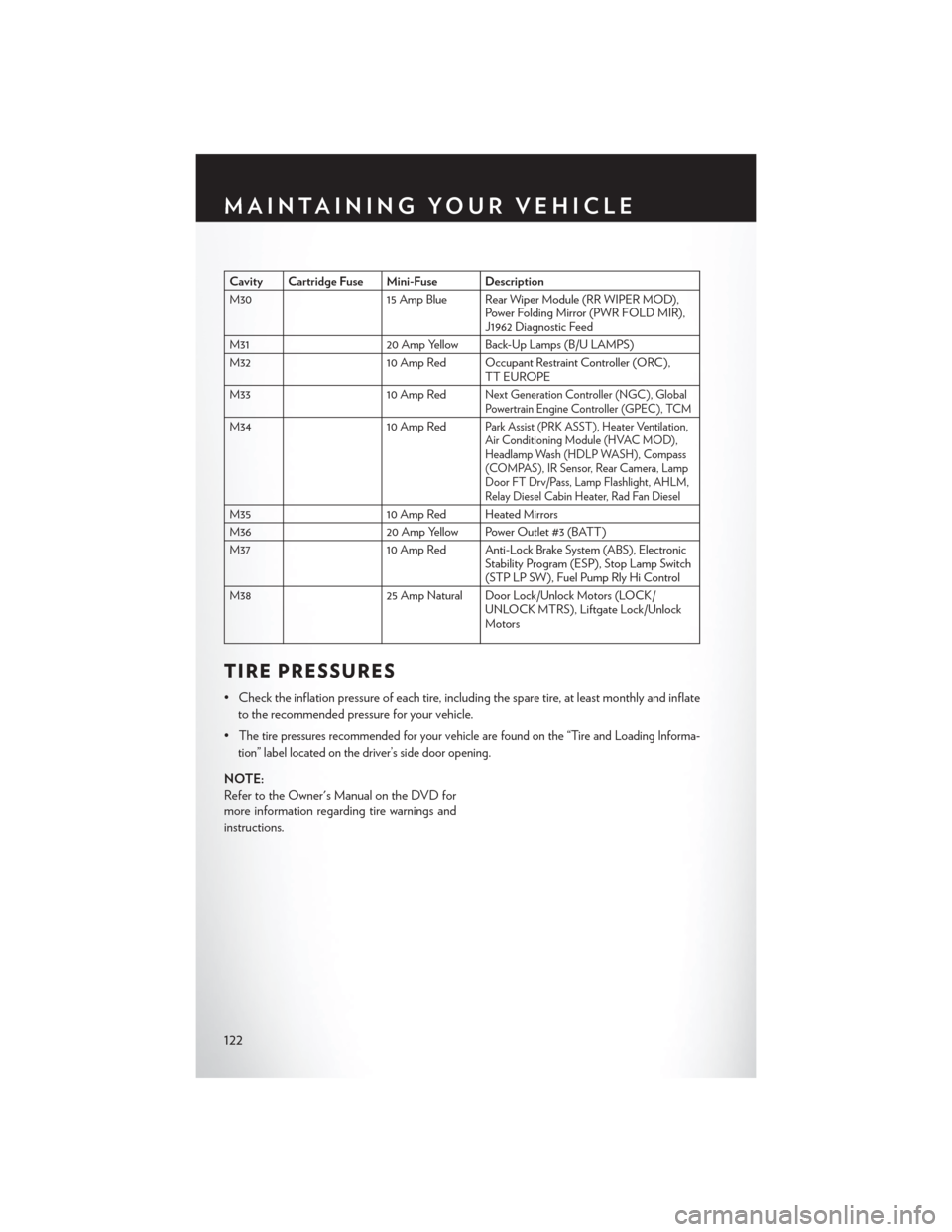
Cavity Cartridge Fuse Mini-Fuse Description
M3015 Amp Blue Rear Wiper Module (RR WIPER MOD),
Power Folding Mirror (PWR FOLD MIR),
J1962 Diagnostic Feed
M31 20 Amp Yellow Back-Up Lamps (B/U LAMPS)
M32 10 Amp Red Occupant Restraint Controller (ORC),
TT EUROPE
M33 10 Amp Red
Next Generation Controller (NGC), Global
Powertrain Engine Controller (GPEC), TCM
M3410 Amp RedPark Assist (PRK ASST), Heater Ventilation,
Air Conditioning Module (HVAC MOD),
Headlamp Wash (HDLP WASH), Compass
(COMPAS), IR Sensor, Rear Camera, Lamp
Door FT Drv/Pass, Lamp Flashlight, AHLM,
Relay Diesel Cabin Heater, Rad Fan Diesel
M3510 Amp Red Heated Mirrors
M36 20 Amp Yellow Power Outlet #3 (BATT)
M37 10 Amp Red Anti-Lock Brake System (ABS), Electronic
Stability Program (ESP), Stop Lamp Switch
(STP LP SW), Fuel Pump Rly Hi Control
M38 25 Amp Natural Door Lock/Unlock Motors (LOCK/
UNLOCK MTRS), Liftgate Lock/Unlock
Motors
TIRE PRESSURES
• Check the inflation pressure of each tire, including the spare tire, at least monthly and inflate
to the recommended pressure for your vehicle.
•
The tire pressures recommended for your vehicle are found on the “Tire and Loading Informa-
tion” label located on the driver’s side door opening.
NOTE:
Refer to the Owner's Manual on the DVD for
more information regarding tire warnings and
instructions.
MAINTAINING YOUR VEHICLE
122