spare tire CHRYSLER TOWN AND COUNTRY 2013 5.G User Guide
[x] Cancel search | Manufacturer: CHRYSLER, Model Year: 2013, Model line: TOWN AND COUNTRY, Model: CHRYSLER TOWN AND COUNTRY 2013 5.GPages: 140, PDF Size: 4.18 MB
Page 93 of 140
ROADSIDE ASSISTANCE
• Dial toll-free 1-800-521-2779 for U.S. Residents or 1-800-363-4869 for Canadian Residents.
• Provide your name, vehicle identification number, license plate number, and your location,including the telephone number from which you are calling.
• Briefly describe the nature of the problem and answer a few simple questions.
• You will be given the name of the service provider and an estimated time of arrival. If you feel you are in an “unsafe situation”, please let us know. With your consent, we will contact local
police or safety authorities.
INSTRUMENT CLUSTER WARNING LIGHTS
- Electronic Stability Control (ESC) Indicator Light
• If this indicator light flashes during acceleration, apply as little throttle as possible. Whiledriving, ease up on the accelerator. Adapt your speed and driving to the prevailing road
conditions. To improve the vehicle's traction when starting off in deep snow, sand or gravel,
it may be desirable to switch the ESC system off.
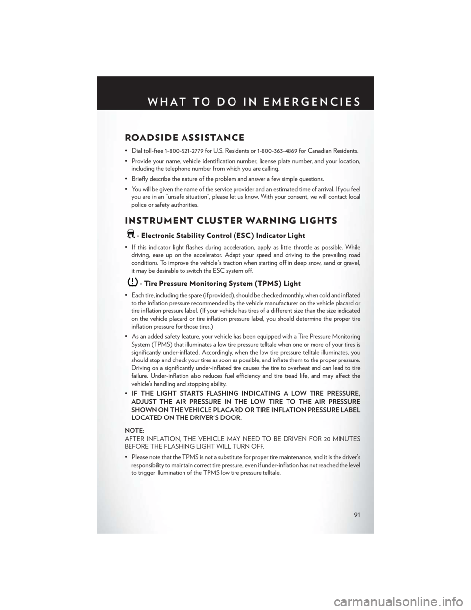
- Tire Pressure Monitoring System (TPMS) Light
• Each tire, including the spare (if provided), should be checked monthly, when cold and inflatedto the inflation pressure recommended by the vehicle manufacturer on the vehicle placard or
tire inflation pressure label. (If your vehicle has tires of a different size than the size indicated
on the vehicle placard or tire inflation pressure label, you should determine the proper tire
inflation pressure for those tires.)
• As an added safety feature, your vehicle has been equipped with a Tire Pressure Monitoring System (TPMS) that illuminates a low tire pressure telltale when one or more of your tires is
significantly under-inflated. Accordingly, when the low tire pressure telltale illuminates, you
should stop and check your tires as soon as possible, and inflate them to the proper pressure.
Driving on a significantly under-inflated tire causes the tire to overheat and can lead to tire
failure. Under-inflation also reduces fuel efficiency and tire tread life, and may affect the
vehicle’s handling and stopping ability.
• IF THE LIGHT STARTS FLASHING INDICATING A LOW TIRE PRESSURE,
ADJUST THE AIR PRESSURE IN THE LOW TIRE TO THE AIR PRESSURE
SHOWN ON THE VEHICLE PLACARD OR TIRE INFLATION PRESSURE LABEL
LOCATED ON THE DRIVER'S DOOR.
NOTE:
AFTER INFLATION, THE VEHICLE MAY NEED TO BE DRIVEN FOR 20 MINUTES
BEFORE THE FLASHING LIGHT WILL TURN OFF.
• Please note that the TPMS is not a substitute for proper tire maintenance, and it is the driver’s responsibility to maintain correct tire pressure, even if under-inflation has not reached the level
to trigger illumination of the TPMS low tire pressure telltale.
WHAT TO DO IN EMERGENCIES
91
Page 98 of 140

JACKING AND TIRE CHANGING
Jack Location
• The jack, jack handle and winch handle toolsare stowed behind the rear left side trim
panel in the rear cargo area. Turn the two
cover latches to release the cover.
• Remove the pouch containing the scissors jack, jack handle, and tools.
Spare Tire Removal
• The spare tire is stowed inside a protective cover located under the center of the ve-
hicle between the front doors by means of
a cable winch mechanism. The “spare tire
drive” nut is located on the floor, under a
plastic cap at the front of the floor console or
under front super console forward bin liner.
To Access Spare Tire Winch Drive Nut
• To access the spare tire winch drive nut and lower the spare tire, you will need to refer to oneof the following center console configurations.
Super Console
• For vehicles equipped with the Super Console, the spare tire winch assembly drive nut islocated beneath the console.
1. Pull the lower drawer out from the rear of the floor console.
WHAT TO DO IN EMERGENCIES
96
Page 99 of 140

2. Open the front drawer to expose the storage compartment.
3. Remove the liner from the console's storagecompartment to access the spare tire winch
drive nut.
Premium/Base/Cargo Center Console
• Pull the Winch Cover assembly plug (if equipped) to access the winch drive nut.
WHAT TO DO IN EMERGENCIES
97
Page 100 of 140

Spare Tire Tools
• The tool pouch contains three pieces and can be assembled into a spare tire hook; to removethe compact spare tire/cover assembly from under the vehicle, or a Winch T-handle; to
raise/lower the compact spare tire/cover assembly.
Assembled T-handle
A - Spare Tire Hook/T-handle
B - Extension 1
C - Extension 2
Assembling The Spare Tire Hook
A - Spare Tire Hook/T-handle
B - Extension 1
C - Extension 2
WHAT TO DO IN EMERGENCIES
98
Page 101 of 140
Spare Tire Removal Instructions
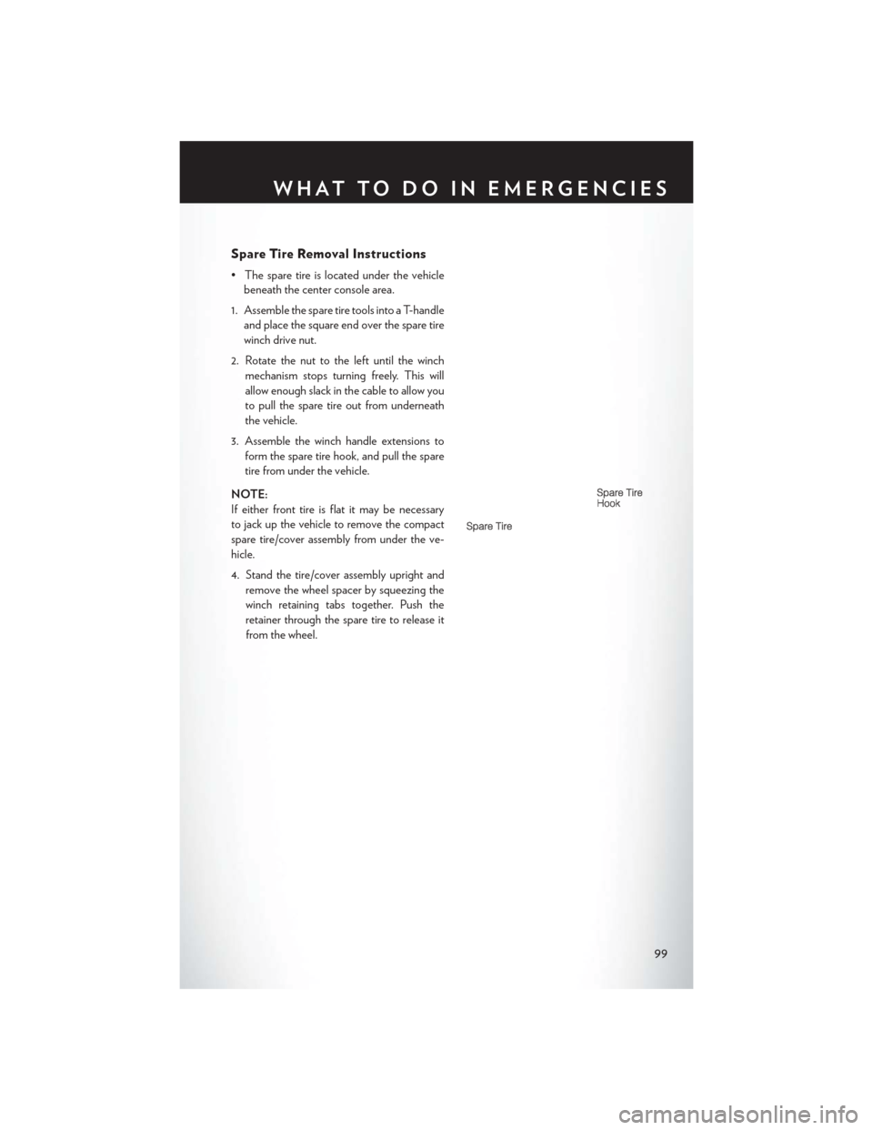
• The spare tire is located under the vehiclebeneath the center console area.
1. Assemble the spare tire tools into a T-handle and place the square end over the spare tire
winch drive nut.
2. Rotate the nut to the left until the winch mechanism stops turning freely. This will
allow enough slack in the cable to allow you
to pull the spare tire out from underneath
the vehicle.
3. Assemble the winch handle extensions to form the spare tire hook, and pull the spare
tire from under the vehicle.
NOTE:
If either front tire is flat it may be necessary
to jack up the vehicle to remove the compact
spare tire/cover assembly from under the ve-
hicle.
4. Stand the tire/cover assembly upright and remove the wheel spacer by squeezing the
winch retaining tabs together. Push the
retainer through the spare tire to release it
from the wheel.
WHAT TO DO IN EMERGENCIES
99
Page 104 of 140
3. Place the wrench on the jack screw and turn to the right until the jack head is properly engagedin the described location. Do not raise the vehicle until you are sure the jack is securely
engaged.
4. Raise the vehicle by turning the jack screw to the right, using the swivel wrench. Raise the vehicle only until the tire just clears the surface and enough clearance is obtained to install the
spare tire. Minimum tire lift provides maximum stability.
5. Remove the wheel lug nuts, for vehicles with wheel covers, remove the cover from the wheel by hand. Do not pry the wheel cover off. Then pull the wheel off the hub.
6. Install the compact spare tire. Lightly tighten the lug nuts.
NOTE:
• Do not install the wheel cover on thecompact spare.
• Do not use a hammer or force to install the wheel covers.
7. Lower the vehicle by turning the jack screw to the left.
8. Finish tightening the lug nuts. Push down on the wrench while at the end of the handle for
increased leverage. Tighten the lug nuts in a
star pattern until each nut has been tightened twice. The correct wheel nut tightness is 102
ft lbs (138 N·m). If in doubt about the correct tightness, have them checked with a torque
wrench by your authorized dealer or at a service station.
9. Lower the jack to its fully-closed position.
10. Place the deflated (flat) tire and compact spare tire cover assembly in the rear cargo area. Do not stow the deflated tire in the spare tire location. Have the full-sized tire repaired or
replaced, as soon as possible.
11. Stow the cable and wheel spacer before driving the vehicle. Reassemble the winch handle extensions to form a “T” and fit the winch T-handle over the drive nut. Rotate the nut to the
right until the winch mechanism clicks at least three times.
NOTE:
Refer to the “Spare Tire Tools” section for instructions on assembling the T-handle.
12. Stow the jack, jack handle and winch handle tools back in the stowage compartment.
13. Check the compact spare tire pressure as soon as possible. Correct the tire pressure, as required.
WHAT TO DO IN EMERGENCIES
102
Page 105 of 140
Securing The Spare Tire
1. Assemble the winch handle extensions to form a T-handle and fit the winch T-handle over thedrive nut. Rotate the nut to the left until the winch mechanism stops turning freely. This will
allow enough slack in the cable to allow you to pull the wheel spacer out from under the vehicle.
2. Assemble the winch handle extensions to form the spare tire hook, and pull the wheel spacer from under the vehicle.
3. Turn the compact spare tire so that the valve stem is down, and place the tire into the spare tire/cover assembly. Slide the wheel spacer through the center of the wheel and spare
tire/cover assembly, so that the two retainer tabs snap out and engage the spare tire cover on
the opposite side.
4. Using the winch T-handle, rotate the drive nut to the right until the compact spare tire/cover assembly is drawn into place against the underside of the vehicle.
5. Continue to rotate the nut to the right until you hear the winch mechanism click three times. It cannot be overtightened. Check under the vehicle to ensure the compact spare tire/cover
assembly is positioned correctly against the underside of the vehicle.
Road Tire Installation
Vehicles Equipped With Wheel Covers
1. Mount the road tire on the axle.
2. To ease the installation process for steel wheels with wheel covers, install two lug nuts on themounting studs which are on each side of the valve stem. Install the lug nuts with the cone
shaped end of the nut toward the wheel. Lightly tighten the lug nuts.
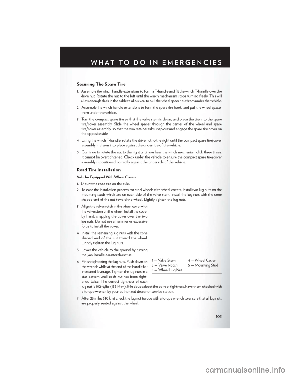
3. Align the valve notch in the wheel cover with the valve stem on the wheel. Install the cover
by hand, snapping the cover over the two
lug nuts. Do not use a hammer or excessive
force to install the cover.
4. Install the remaining lug nuts with the cone shaped end of the nut toward the wheel.
Lightly tighten the lug nuts.
5. Lower the vehicle to the ground by turning the jack handle counterclockwise.
6. Finish tightening the lug nuts. Push down on the wrench while at the end of the handle for
increased leverage. Tighten the lug nuts in a
star pattern until each nut has been tight-
ened twice. The correct tightness of each
lug nut is 102 ft/lbs (138 N·m). If in doubt about the correct tightness, have them checked with
a torque wrench by your authorized dealer or service station.
7. After 25 miles (40 km) check the lug nut torque with a torque wrench to ensure that all lug nuts are properly seated against the wheel.
1 — Valve Stem 4 — Wheel Cover
2 — Valve Notch 5 — Mounting Stud
3 — Wheel Lug Nut
WHAT TO DO IN EMERGENCIES
103
Page 106 of 140
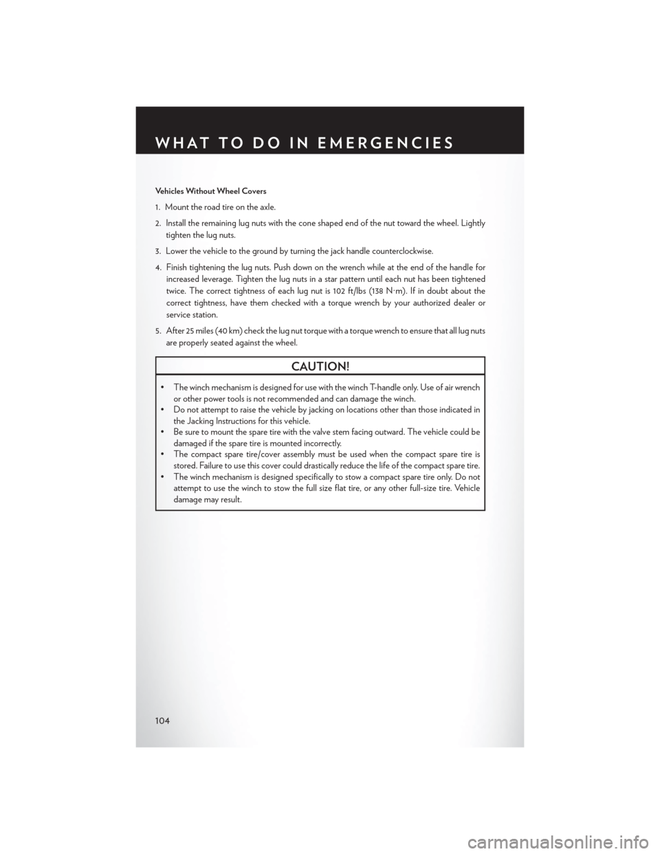
Vehicles Without Wheel Covers
1. Mount the road tire on the axle.
2. Install the remaining lug nuts with the cone shaped end of the nut toward the wheel. Lightlytighten the lug nuts.
3. Lower the vehicle to the ground by turning the jack handle counterclockwise.
4. Finish tightening the lug nuts. Push down on the wrench while at the end of the handle for increased leverage. Tighten the lug nuts in a star pattern until each nut has been tightened
twice. The correct tightness of each lug nut is 102 ft/lbs (138 N·m). If in doubt about the
correct tightness, have them checked with a torque wrench by your authorized dealer or
service station.
5. After 25 miles (40 km) check the lug nut torque with a torque wrench to ensure that all lug nuts are properly seated against the wheel.
CAUTION!
• The winch mechanism is designed for use with the winch T-handle only. Use of air wrench or other power tools is not recommended and can damage the winch.
• Do not attempt to raise the vehicle by jacking on locations other than those indicated in
the Jacking Instructions for this vehicle.
• Be sure to mount the spare tire with the valve stem facing outward. The vehicle could be
damaged if the spare tire is mounted incorrectly.
• The compact spare tire/cover assembly must be used when the compact spare tire is
stored. Failure to use this cover could drastically reduce the life of the compact spare tire.
• The winch mechanism is designed specifically to stow a compact spare tire only. Do not attempt to use the winch to stow the full size flat tire, or any other full-size tire. Vehicle
damage may result.
WHAT TO DO IN EMERGENCIES
104
Page 107 of 140
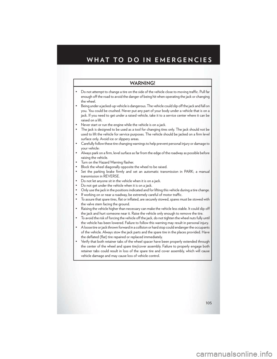
WARNING!
• Do not attempt to change a tire on the side of the vehicle close to moving traffic. Pull farenough off the road to avoid the danger of being hit when operating the jack or changing
the wheel.
• Being under a jacked-up vehicle is dangerous. The vehicle could slip off the jack and fall on
you. You could be crushed. Never put any part of your body under a vehicle that is on a
jack. If you need to get under a raised vehicle, take it to a service center where it can be
raised on a lift.
• Never start or run the engine while the vehicle is on a jack.
• The jack is designed to be used as a tool for changing tires only. The jack should not be
used to lift the vehicle for service purposes. The vehicle should be jacked on a firm level
surface only. Avoid ice or slippery areas.
• Carefully follow these tire changing warnings to help prevent personal injury or damage to
your vehicle:
• Always park on a firm, level surface as far from the edge of the roadway as possible before
raising the vehicle.
• Turn on the Hazard Warning flasher.
• Block the wheel diagonally opposite the wheel to be raised.
• Set the parking brake firmly and set an automatic transmission in PARK; a manual
transmission in REVERSE.
• Do not let anyone sit in the vehicle when it is on a jack.
• Do not get under the vehicle when it is on a jack.
• Only use the jack in the positions indicated and for lifting this vehicle during a tire change.
• If working on or near a roadway, be extremely careful of motor traffic.
• To assure that spare tires, flat or inflated, are securely stowed, spares must be stowed with
the valve stem facing the ground.
• Raising the vehicle higher than necessary can make the vehicle less stable. It could slip off
the jack and hurt someone near it. Raise the vehicle only enough to remove the tire.
• To avoid the risk of forcing the vehicle off the jack, do not tighten the wheel nuts fully until
the vehicle has been lowered. Failure to follow this warning may result in personal injury.
• A loose tire or jack thrown forward in a collision or hard stop could endanger the occupants
of the vehicle. Always stow the jack parts and the spare tire in the places provided. Have
the deflated (flat) tire repaired or replaced immediately.
• Verify that both retainer tabs of the wheel spacer have been properly extended through
the center of the wheel and spare tire/cover assembly. Failure to properly engage both
retainer tabs could result in loss of the spare tire and cover assembly, which will cause
vehicle damage and may cause loss of vehicle control.
WHAT TO DO IN EMERGENCIES
105
Page 124 of 140
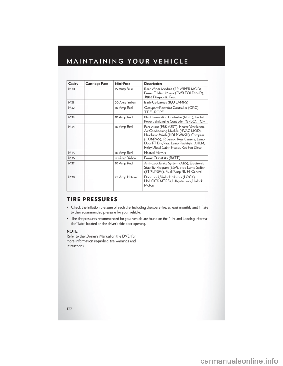
Cavity Cartridge Fuse Mini-Fuse Description
M3015 Amp Blue Rear Wiper Module (RR WIPER MOD),
Power Folding Mirror (PWR FOLD MIR),
J1962 Diagnostic Feed
M31 20 Amp Yellow Back-Up Lamps (B/U LAMPS)
M32 10 Amp Red Occupant Restraint Controller (ORC),
TT EUROPE
M33 10 Amp Red
Next Generation Controller (NGC), Global
Powertrain Engine Controller (GPEC), TCM
M3410 Amp RedPark Assist (PRK ASST), Heater Ventilation,
Air Conditioning Module (HVAC MOD),
Headlamp Wash (HDLP WASH), Compass
(COMPAS), IR Sensor, Rear Camera, Lamp
Door FT Drv/Pass, Lamp Flashlight, AHLM,
Relay Diesel Cabin Heater, Rad Fan Diesel
M3510 Amp Red Heated Mirrors
M36 20 Amp Yellow Power Outlet #3 (BATT)
M37 10 Amp Red Anti-Lock Brake System (ABS), Electronic
Stability Program (ESP), Stop Lamp Switch
(STP LP SW), Fuel Pump Rly Hi Control
M38 25 Amp Natural Door Lock/Unlock Motors (LOCK/
UNLOCK MTRS), Liftgate Lock/Unlock
Motors
TIRE PRESSURES
• Check the inflation pressure of each tire, including the spare tire, at least monthly and inflate
to the recommended pressure for your vehicle.
•
The tire pressures recommended for your vehicle are found on the “Tire and Loading Informa-
tion” label located on the driver’s side door opening.
NOTE:
Refer to the Owner's Manual on the DVD for
more information regarding tire warnings and
instructions.
MAINTAINING YOUR VEHICLE
122