steering CHRYSLER TOWN AND COUNTRY 2014 5.G Owner's Manual
[x] Cancel search | Manufacturer: CHRYSLER, Model Year: 2014, Model line: TOWN AND COUNTRY, Model: CHRYSLER TOWN AND COUNTRY 2014 5.GPages: 148, PDF Size: 4.26 MB
Page 76 of 148
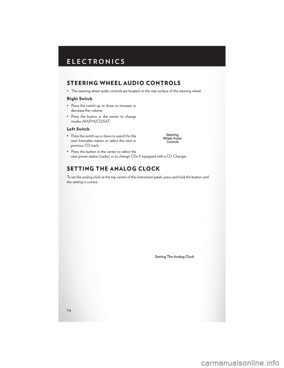
STEERING WHEEL AUDIO CONTROLS
• The steering wheel audio controls are located on the rear surface of the steering wheel.
Right Switch
• Press the switch up or down to increase ordecrease the volume.
• Press the button in the center to change modes AM/FM/CD/SAT.
Left Switch
• Press the switch up or down to search for thenext listenable station or select the next or
previous CD track.
• Press the button in the center to select the next preset station (radio) or to change CDs if equipped with a CD Changer.
SETTING THE ANALOG CLOCK
To set the analog clock at the top center of the instrument panel, press and hold the button until
the setting is correct.
Setting The Analog Clock
ELECTRONICS
74
Page 80 of 148
Mute (Or Unmute) Microphone During Call
• During a call, press the “Voice Command” button.
• After the BEEP, say “mute” (or “mute off ”).
Transfer Ongoing Call Between Handset And Vehicle
• During a call, press the “Voice Command” button.
• After the BEEP, say “transfer call.”
Changing The Volume
• Start a dialogue by pressing the “Phone” button, then adjust the volume during a normal
call.
• Use the radio ON/OFF VOLUME rotary knob to adjust the volume to a comfortable level while the Uconnect® system is speaking. Please note the volume setting for Uconnect® is
different than the audio system.
WARNING!
• Any voice commanded system should be used only in safe driving conditions following
applicable laws regarding phone use. Your attention should be focused on safely operating
the vehicle. Failure to do so may result in a collision causing you and others to be severely
injured or killed.
• In an emergency, to use Uconnect® Phone, your mobile phone must be:
• turned on,
• paired to Uconnect® Phone,
• and have network coverage.
Uconnect® VOICE COMMAND
Voice Command Operation
• The Uconnect® Voice Command system allows you to control your AM, FM radio, satelliteradio, disc player, HDD, Uconnect® Phone, a memo recorder, and supported portable media
devices.
• When you press the “Voice Command” button
located on the radio faceplate or
steering wheel, you will hear a beep. The beep is your signal to give a command. If you do not
say a command within a few seconds, the system will present you with a list of options. If you
ever want to interrupt the system while it lists options, press the “Voice Command” button
, listen for the BEEP, and say your command.
NOTE:
Visit http://www.driveuconnect.com/features/voiceCommand/ for more info on which voice
command features apply to your vehicle.
ELECTRONICS
78
Page 85 of 148
ELECTRONIC VEHICLE INFORMATION
CENTER (EVIC)
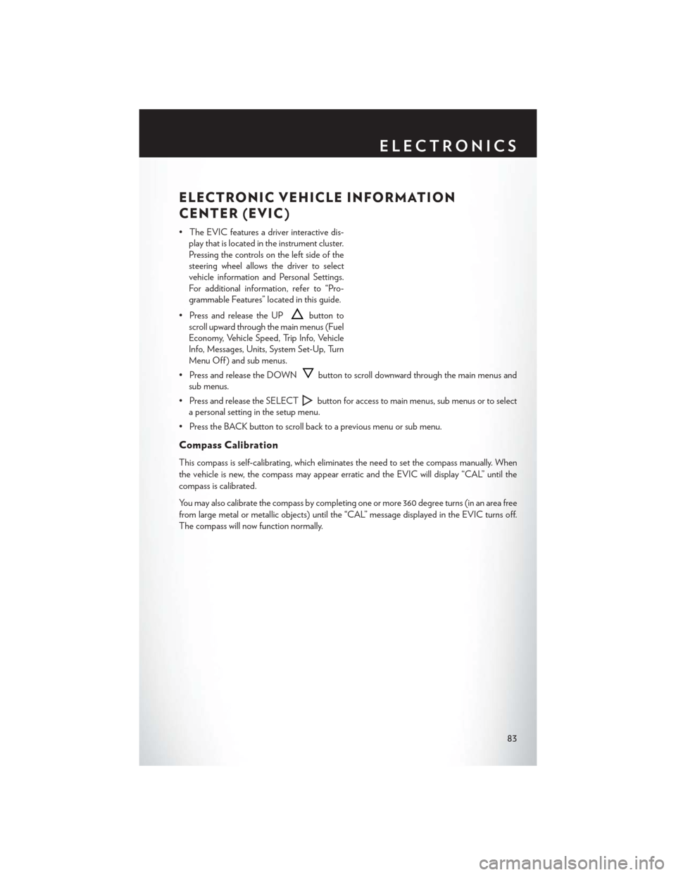
• The EVIC features a driver interactive dis-play that is located in the instrument cluster.
Pressing the controls on the left side of the
steering wheel allows the driver to select
vehicle information and Personal Settings.
For additional information, refer to “Pro-
grammable Features” located in this guide.
• Press and release the UP
button to
scroll upward through the main menus (Fuel
Economy, Vehicle Speed, Trip Info, Vehicle
Info, Messages, Units, System Set-Up, Turn
Menu Off ) and sub menus.
• Press and release the DOWN
button to scroll downward through the main menus and
sub menus.
• Press and release the SELECT
button for access to main menus, sub menus or to select
a personal setting in the setup menu.
• Press the BACK button to scroll back to a previous menu or sub menu.
Compass Calibration
This compass is self-calibrating, which eliminates the need to set the compass manually. When
the vehicle is new, the compass may appear erratic and the EVIC will display “CAL” until the
compass is calibrated.
You may also calibrate the compass by completing one or more 360 degree turns (in an area free
from large metal or metallic objects) until the “CAL” message displayed in the EVIC turns off.
The compass will now function normally.
ELECTRONICS
83
Page 116 of 148

FREEING A STUCK VEHICLE
• If your vehicle becomes stuck in mud, sand or snow, it can often be moved using a rockingmotion. Turn your steering wheel right and left to clear the area around the front wheels. Then
shift back and forth between DRIVE and REVERSE while gently pressing the accelerator. Use
the least amount of accelerator pedal pressure that will maintain the rocking motion, without
spinning the wheels or racing the engine.
NOTE:
Press the "ESC Off" switch, to place the Electronic Stability Control (ESC) system in "Partial
Off" mode before rocking the vehicle. Once the vehicle has been freed, press the "ESC Off"
switch again to restore "ESC On" mode.
CAUTION!
• When “rocking” a stuck vehicle by shifting between REVERSE and DRIVE, do not spin the wheels faster than 15 mph (24 km/h), or drivetrain damage may result.
• Revving the engine or spinning the wheels too fast may lead to transmission overheating
and failure. It can also damage the tires. Do not spin the wheels above 30 mph (48 km/h)
while in gear (no transmission shifting occurring).
WARNING!
Fast spinning tires can be dangerous. Forces generated by excessive wheel speeds may cause
tire damage or failure. A tire could explode and injure someone. Do not spin your vehicle's
wheels faster than 30 mph (48 km/h) when you are stuck. Do not let anyone near a spinning
wheel, no matter what the speed.
WHAT TO DO IN EMERGENCIES
114
Page 118 of 148
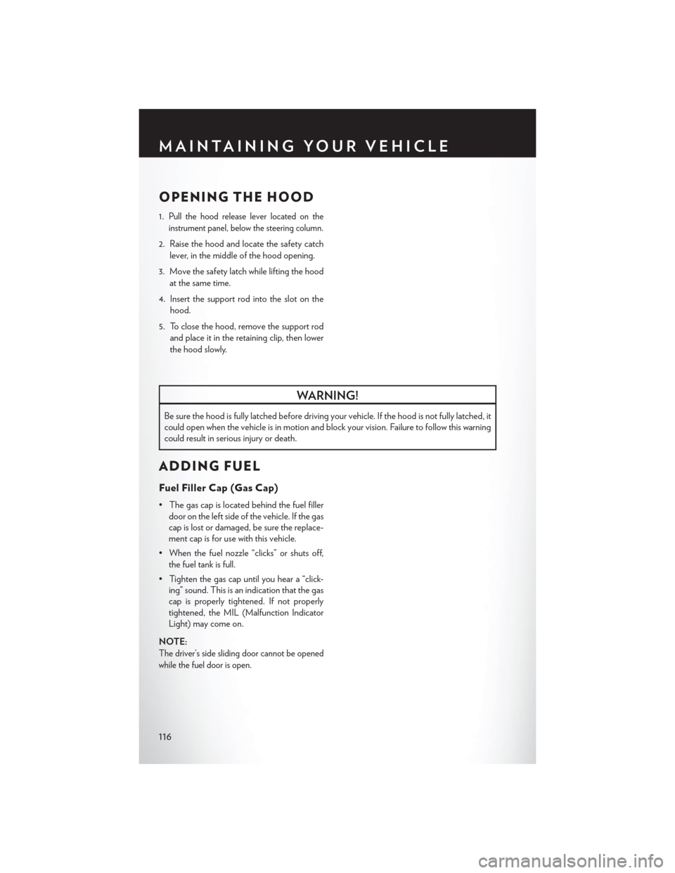
OPENING THE HOOD
1.Pull the hood release lever located on the
instrument panel, below the steering column.
2. Raise the hood and locate the safety catch lever, in the middle of the hood opening.
3. Move the safety latch while lifting the hood at the same time.
4. Insert the support rod into the slot on the hood.
5. To close the hood, remove the support rod and place it in the retaining clip, then lower
the hood slowly.
WARNING!
Be sure the hood is fully latched before driving your vehicle. If the hood is not fully latched, it
could open when the vehicle is in motion and block your vision. Failure to follow this warning
could result in serious injury or death.
ADDING FUEL
Fuel Filler Cap (Gas Cap)
• The gas cap is located behind the fuel fillerdoor on the left side of the vehicle. If the gas
cap is lost or damaged, be sure the replace-
ment cap is for use with this vehicle.
• When the fuel nozzle “clicks” or shuts off, the fuel tank is full.
• Tighten the gas cap until you hear a “click- ing” sound. This is an indication that the gas
cap is properly tightened. If not properly
tightened, the MIL (Malfunction Indicator
Light) may come on.
NOTE:
The driver’s side sliding door cannot be opened
while the fuel door is open.
MAINTAINING YOUR VEHICLE
116
Page 121 of 148
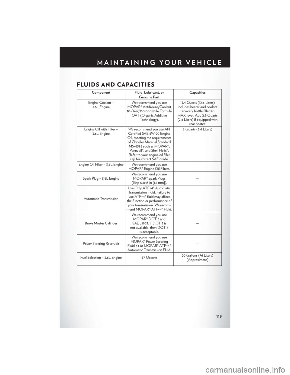
FLUIDS AND CAPACITIES
ComponentFluid, Lubricant, or
Genuine Part Capacities
Engine Coolant – 3.6L Engine We recommend you use
MOPAR® Antifreeze/Coolant
10–Year/150,000 Mile Formula OAT (Organic Additive Technology). 13.4 Quarts (12.6 Liters)
Includes heater and coolant recovery bottle filled to
MAX level. Add 2.9 Quarts (2.8 Liters) if equipped with rear heater.
Engine Oil with Filter – 3.6L Engine We recommend you use API
Certified SAE 5W-20 Engine
Oil, meeting the requirements of Chrysler Material Standard MS-6395 such as MOPAR®,Pennzoil®, and Shell Helix®.
Refer to your engine oil filler cap for correct SAE grade. 6 Quarts (5.6 Liters)
Engine Oil Filter – 3.6L Engine We recommend you use MOPAR® Engine Oil Filters. —
Spark Plug – 3.6L Engine We recommend you use
MOPAR® Spark Plugs
(Gap 0.043 in [1.1 mm]). —
Automatic Transmission Use Only ATF+4® Automatic
Transmission Fluid. Failure touse ATF+4® fluid may affect
the function or performance of your transmission. We recom-
mend MOPAR® ATF+4® Fluid. —
Brake Master Cylinder We recommend you use
MOPAR® DOT 3 and
SAE J1703. If DOT 3 is
not available, then DOT 4 is acceptable. —
Power Steering Reservoir We recommend you use
MOPAR® Power Steering
Fluid +4 or MOPAR® ATF+4® Automatic Transmission Fluid. —
Fuel Selection – 3.6L Engine 87 Octane20 Gallons (76 Liters)
(Approximate)
MAINTAINING YOUR VEHICLE
119
Page 123 of 148
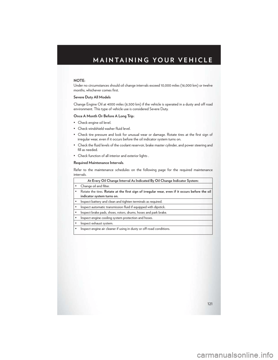
NOTE:
Under no circumstances should oil change intervals exceed 10,000 miles (16,000 km) or twelve
months, whichever comes first.
Severe Duty All Models
Change Engine Oil at 4000 miles (6,500 km) if the vehicle is operated in a dusty and off road
environment. This type of vehicle use is considered Severe Duty.
Once A Month Or Before A Long Trip:
• Check engine oil level.
• Check windshield washer fluid level.
• Check tire pressure and look for unusual wear or damage. Rotate tires at the first sign ofirregular wear, even if it occurs before the oil indicator system turns on.
• Check the fluid levels of the coolant reservoir, brake master cylinder, and power steering and fill as needed.
• Check function of all interior and exterior lights .
Required Maintenance Intervals.
Refer to the maintenance schedules on the following page for the required maintenance
intervals.
At Every Oil Change Interval As Indicated By Oil Change Indicator System:
• Change oil and filter.
• Rotate the tires. Rotate at the first sign of irregular wear, even if it occurs before the oil
indicator system turns on.
• Inspect battery and clean and tighten terminals as required.
• Inspect automatic transmission fluid if equipped with dipstick.
• Inspect brake pads, shoes, rotors, drums, hoses and park brake.
• Inspect engine cooling system protection and hoses.
• Inspect exhaust system.
• Inspect engine air cleaner if using in dusty or off-road conditions.
MAINTAINING YOUR VEHICLE
121
Page 129 of 148
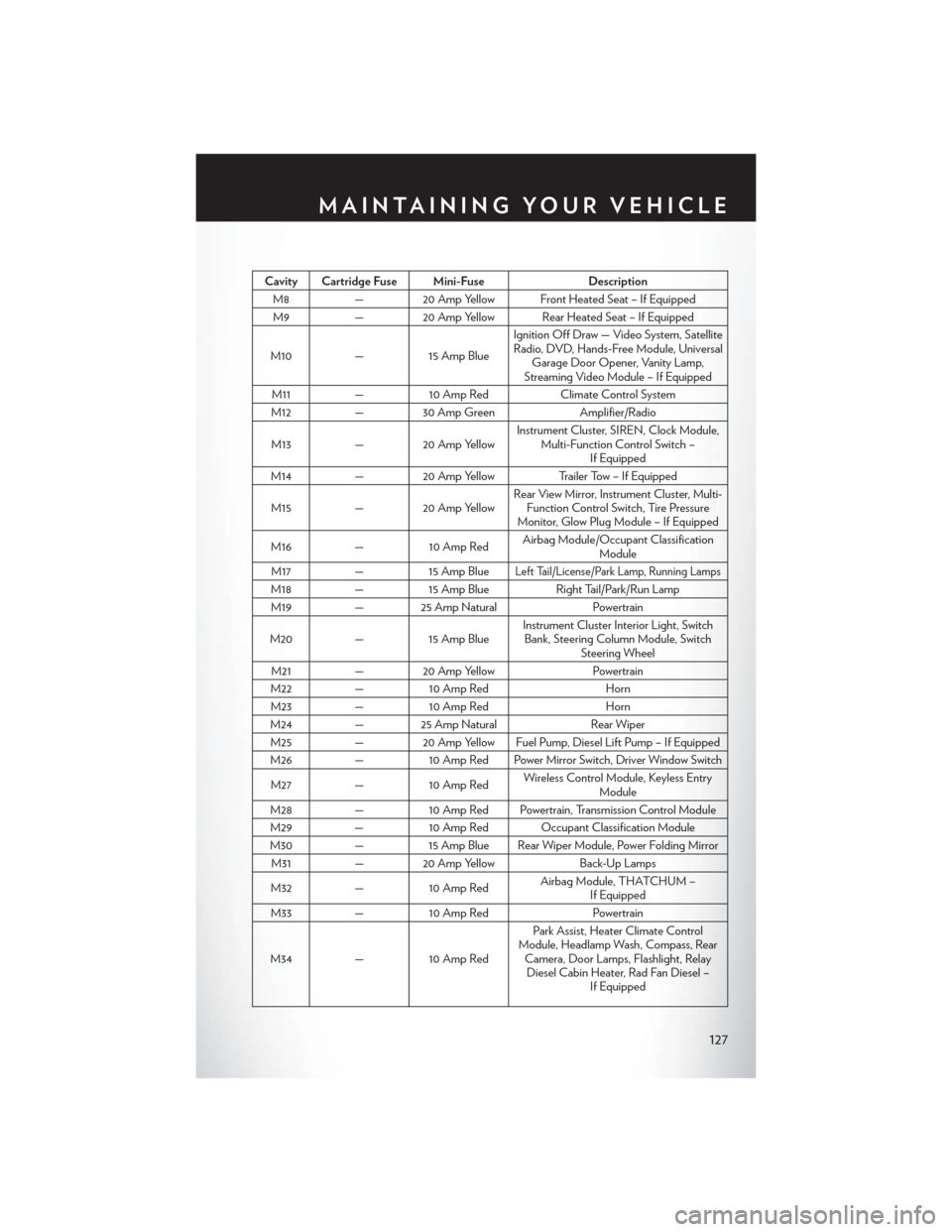
Cavity Cartridge Fuse Mini-FuseDescription
M8 — 20 Amp Yellow Front Heated Seat – If Equipped
M9 — 20 Amp Yellow Rear Heated Seat – If Equipped
M10 —15 Amp Blue Ignition Off Draw — Video System, Satellite
Radio, DVD, Hands-Free Module, Universal Garage Door Opener, Vanity Lamp,
Streaming Video Module – If Equipped
M11 —10 Amp Red Climate Control System
M12 — 30 Amp Green Amplifier/Radio
M13 — 20 Amp Yellow Instrument Cluster, SIREN, Clock Module,
Multi-Function Control Switch – If Equipped
M14 — 20 Amp Yellow Trailer Tow – If Equipped
M15 — 20 Amp Yellow Rear View Mirror, Instrument Cluster, Multi-
Function Control Switch, Tire Pressure
Monitor, Glow Plug Module – If Equipped
M16 —10 Amp Red Airbag Module/Occupant Classification
Module
M17 —15 Amp Blue
Left Tail/License/Park Lamp, Running Lamps
M18 —15 Amp Blue Right Tail/Park/Run Lamp
M19 — 25 Amp Natural Powertrain
M20 —15 Amp Blue Instrument Cluster Interior Light, Switch
Bank, Steering Column Module, Switch Steering Wheel
M21 — 20 Amp Yellow Powertrain
M22 —10 Amp Red Horn
M23 —10 Amp Red Horn
M24 — 25 Amp Natural Rear Wiper
M25 — 20 Amp Yellow Fuel Pump, Diesel Lift Pump – If Equipped
M26 —10 Amp Red Power Mirror Switch, Driver Window Switch
M27 —10 Amp Red Wireless Control Module, Keyless Entry
Module
M28 —10 Amp Red Powertrain, Transmission Control Module
M29 —10 Amp Red Occupant Classification Module
M30 —15 Amp Blue Rear Wiper Module, Power Folding Mirror
M31 — 20 Amp Yellow Back-Up Lamps
M32 —10 Amp Red Airbag Module, THATCHUM –
If Equipped
M33 —10 Amp Red Powertrain
M34 —10 Amp Red Park Assist, Heater Climate Control
Module, Headlamp Wash, Compass, Rear Camera, Door Lamps, Flashlight, RelayDiesel Cabin Heater, Rad Fan Diesel – If Equipped
MAINTAINING YOUR VEHICLE
127
Page 130 of 148
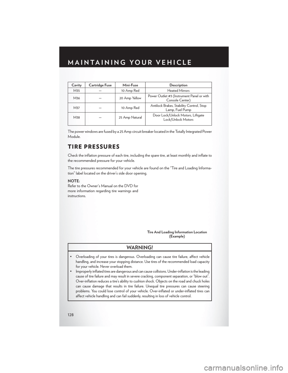
Cavity Cartridge Fuse Mini-FuseDescription
M35 —10 Amp Red Heated Mirrors
M36 — 20 Amp Yellow Power Outlet #3 (Instrument Panel or with
Console Center)
M37 —10 Amp Red Antilock Brakes, Stability Control, Stop
Lamp, Fuel Pump
M38 — 25 Amp Natural Door Lock/Unlock Motors, Liftgate
Lock/Unlock Motors
The power windows are fused by a 25 Amp circuit breaker located in the Totally Integrated Power
Module.
TIRE PRESSURES
Check the inflation pressure of each tire, including the spare tire, at least monthly and inflate to
the recommended pressure for your vehicle.
The tire pressures recommended for your vehicle are found on the “Tire and Loading Informa-
tion” label located on the driver’s side door opening.
NOTE:
Refer to the Owner's Manual on the DVD for
more information regarding tire warnings and
instructions.
WARNING!
•Overloading of your tires is dangerous. Overloading can cause tire failure, affect vehicle
handling, and increase your stopping distance. Use tires of the recommended load capacity
for your vehicle. Never overload them.
•Improperly inflated tires are dangerous and can cause collisions. Under-inflation is the leading
cause of tire failure and may result in severe cracking, component separation, or “blow out”.
Over-inflation reduces a tire’s ability to cushion shock. Objects on the road and chuck holes
can cause damage that results in tire failure. Unequal tire pressures can cause steering
problems. You could lose control of your vehicle. Over-inflated or under-inflated tires can
affect vehicle handling and can fail suddenly, resulting in loss of vehicle control.
Tire And Loading Information Location (Example)
MAINTAINING YOUR VEHICLE
128
Page 138 of 148
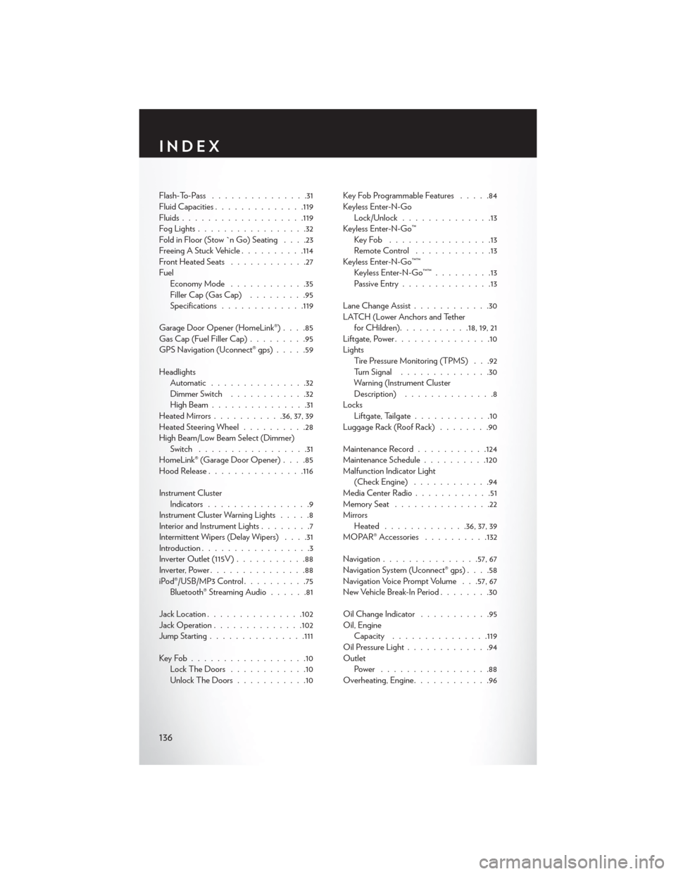
Flash-To-Pass...............31
Fluid Capacities ............. .119
Fluids .................. .119
FogLights.................32
Fold in Floor (Stow `n Go) Seating ....23
Freeing A Stuck Vehicle ..........114
Front Heated Seats ............27
Fuel EconomyMode ............35
Filler Cap (Gas Cap) .........95
Specifications ............ .119
Garage Door Opener (HomeLink®) ....85
Gas Cap (Fuel Filler Cap) .........95
GPS Navigation (Uconnect® gps) .....59
Headlights Automatic ...............32
Dimmer Switch ............32
HighBeam...............31
Heated Mirrors ...........36, 37, 39
Heated Steering Wheel ..........28
High Beam/Low Beam Select (Dimmer) Switch .................31
HomeLink® (Garage Door Opener) ....85
Hood Release .............. .116
Instrument Cluster Indicators ................9
Instrument Cluster Warning Lights .....8
Interior and Instrument Lights ........7
Intermittent Wipers (Delay Wipers) ....31
Introduction .................3
Inverter Outlet (115V) ...........88
Inverter, Power ...............88
iPod®/USB/MP3 Control ..........75
Bluetooth® Streaming Audio ......81
Jack Location .............. .102
Jack Operation ............. .102
Jump Starting .............. .111
KeyFob..................10 LockTheDoors ............10
Unlock The Doors ...........10 Key Fob Programmable Features
.....84
Keyless Enter-N-Go Lock/Unlock ..............13
Keyless Enter-N-Go™ KeyFob ................13
RemoteControl ............13
Keyless Enter-N-Go™™ Keyless Enter-N-Go™™ .........13
Passive Entry ..............13
Lane Change Assist ............30
LATCH (Lower Anchors and Tether for CHildren) ...........18,19,21
Liftgate, Power ...............10
Lights Tire Pressure Monitoring (TPMS) . . .92
Turn Signal ..............30
Warning (Instrument Cluster
Description) ..............8
Locks Liftgate
, Tailgate............10
Luggage Rack (Roof Rack) ........90
Maintenance Record ...........124
Maintenance Schedule ..........120
Malfunction Indicator Light (Check Engine) ............94
Media Center Radio ............51
Memory Seat ...............22
Mirrors Heated ............ .36, 37, 39
MOPAR® Accessories ..........132
Navigation .............. .57, 67
Navigation System (Uconnect® gps) ....58
Navigation Voice Prompt Volume . . .57, 67
New Vehicle Break-In Period ........30
Oil Change Indicator ...........95
Oil, Engine Capacity .............. .119
Oil Pressure Light .............94
Outlet Power .................88
Overheating, Engine ............96
INDEX
136