warning CHRYSLER TOWN AND COUNTRY 2015 5.G Owner's Manual
[x] Cancel search | Manufacturer: CHRYSLER, Model Year: 2015, Model line: TOWN AND COUNTRY, Model: CHRYSLER TOWN AND COUNTRY 2015 5.GPages: 164, PDF Size: 22.47 MB
Page 28 of 164
Active Head Restraints — Front Seats
Active Head Restraints are passive, deployable components, and vehicles with this equipment
cannot be readily identified by any markings, only through visual inspection of the head restraint.
The Active Head Restraints (AHR) will be split in two halves, with the front half being soft foam
and trim, the back half being decorative plastic.
When AHRs deploy during a rear impact, the front half of the head restraint extends forward to
minimize the gap between the back of the occupant’s head and the AHR. This system is designed
to help prevent or reduce the extent of injuries to the driver and front passenger in certain types
of rear impacts. Refer to “Occupant Restraints” in your Owner’s Manual on the DVD for further
information.
To raise the head restraint, pull upward on the head restraint. To lower the head restraint, press the
push button, located at the base of the head restraint, and push downward on the head restraint.
For comfort the Active Head Restraints can be tilted forward and rearward. To tilt the head
restraint closer to the back of your head, pull forward on the bottom of the head restraint. Push
rearward on the bottom of the head restraint to move the head restraint away from your head.
NOTE:
•Theheadrestraintsshouldonlyberemovedbyqualifiedtechnicians,forservicepurposesonly.
If either of the head restraints require removal, see your authorized dealer.
•IntheeventofdeploymentofanActiveHeadRestraint, refer to “Occupant Restraints” in your
Owner’s Manual on the DVD for further information.
WARNING!
•DonotplaceitemsoverthetopoftheActiveHeadRestraint,suchascoats,seatcoversor
portable DVD players. These items may interfere with the operation of the Active Head
Restraint in the event of a collision and could result in serious injury or death.
•ActiveHeadRestraintsmaybedeployediftheyarestruckbyanobjectsuchasahand,
foot or loose cargo. To avoid accidental deployment of the Active Head Restraint ensure
that all cargo is secured, as loose cargo could contact the Active Head Restraint during
sudden stops. Failure to follow this warning could cause personal injury if the Active Head
Restraint is deployed.
Head Restraints — Second Row Quad Seats
To raise the head restraint, pull upward on the head restraint. To lower the head restraint, press the
push button, located at the base of the head restraint, and push downward on the head restraint.
Head Restraints — Second Row Bench
If your vehicle is equipped with a second row bench seat, the head restraints are not adjustable.
Head Restraints — Third Row
The head restraint in the center position can be raised and lowered for tether routing. Refer to
“Occupant Restraints” in your Owner’s Manual on the DVD for further information.
GETTING STARTED
26
Page 30 of 164
Memory Seat
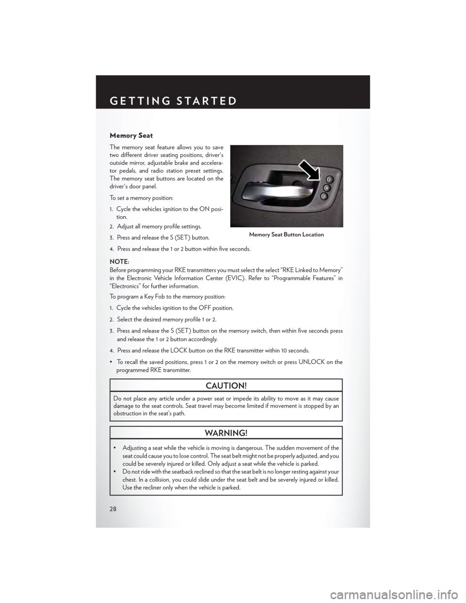
The memory seat feature allows you to save
two different driver seating positions, driver's
outside mirror, adjustable brake and accelera-
tor pedals, and radio station preset settings.
The memory seat buttons are located on the
driver's door panel.
To set a memory position:
1. Cycle the vehicles ignition to the ON posi-
tion.
2. Adjust all memory profile settings.
3. Press and release the S (SET) button.
4. Press and release the 1 or 2 button within five seconds.
NOTE:
Before programming your RKE transmitters you must select the select “RKE Linked to Memory”
in the Electronic Vehicle Information Center (EVIC). Refer to “Programmable Features” in
“Electronics” for further information.
To program a Key Fob to the memory position:
1. Cycle the vehicles ignition to the OFF position.
2. Select the desired memory profile 1 or 2.
3. Press and release the S (SET) button on the memory switch, then within five seconds press
and release the 1 or 2 button accordingly.
4. Press and release the LOCK button on the RKE transmitter within 10 seconds.
•Torecallthesavedpositions,press1or2onthememoryswitchorpressUNLOCKonthe
programmed RKE transmitter.
CAUTION!
Do not place any article under a power seat or impede its ability to move as it may causedamage to the seat controls. Seat travel may become limited if movement is stopped by anobstruction in the seat’s path.
WARNING!
•Adjustingaseatwhilethevehicleismovingisdangerous.Thesuddenmovementofthe
seat could cause you to lose control. The seat belt might not be properly adjusted, and you
could be severely injured or killed. Only adjust a seat while the vehicle is parked.
•Donotridewiththeseatbackreclinedsothattheseatbeltisnolongerrestingagainstyour
chest. In a collision, you could slide under the seat belt and be severely injured or killed.
Use the recliner only when the vehicle is parked.
Memory Seat Button Location
GETTING STARTED
28
Page 35 of 164

5. Pull release strap marked “4” and tumble the seat rearward into the storage bin.
To Unfold Third Row Seats
1. Pull up on the assist strap to lift the seat out
of the storage bin and push the seat forward
until the anchors latch.
2. Pull release strap marked “2” to unlock the
recliner.
3. Pulling strap “4” releases the seatback to
return to its full upright position.
4.Raise the head restraint to its upright position.
CAUTION!
The storage bin cover must be locked and flat to avoid damage from contact with the front
seat tracks, which have minimal clearance to the cover.
WARNING!
•Inacollision,seriousinjurycouldresultiftheseatstoragebincoversarenotproperly
latched.
•Donotdrivethevehiclewiththestoragebincoversopen.
•Keepthestoragebincoversclosedandlatchedwhilethevehicleisinmotion.
• Do not use a storage bin latch as a tie down.
•Inacollision,youorothersinthevehiclecouldbeinjurediftheseatsarenotproperly
latched to their floor attachments. Always be sure the seats are fully latched.
Seats In Stowed Position
GETTING STARTED
33
Page 36 of 164

HEATED SEATS
Front Heated Seats
The controls for front heated seats are located
on the center instrument panel area.
•PresstheswitchoncetoselectHigh-level
heating. Press the switch a second time to
select Low-level heating. Press the switch a
third time to shut the heating elements Off.
If the High-level setting is selected, the system
will automatically switch to Low-level after ap-
proximately 60 minutes. The Low-level setting
will turn Off automatically after approximately
45 minutes.
Second Row Heated Seats
Second row heated seat switches are located in
the sliding door handle trim panels.
•PresstheswitchoncetoselectHigh-level
heating. Press the switch a second time to
select Low-level heating. Press the switch a
third time to shut the heating elements Off.
If the High-level setting is selected, the system
will automatically switch to Low-level after ap-
proximately 60 minutes. The Low-level setting
will turn Off automatically after approximately
45 minutes.
WARNING!
•Personswhoareunabletofeelpaintotheskinbecauseofadvancedage,chronicillness,
diabetes, spinal cord injury, medication, alcohol use, exhaustion or other physical condi-
tions must exercise care when using the seat heater. It may cause burns even at low
temperatures, especially if used for long periods of time.
• Do not place anything on the seat that insulates against heat, such as a blanket or cushion.
This may cause the seat heater to overheat. Sitting in a seat that has been overheated
could cause serious burns due to the increased surface temperature of the seat.
Heated Seat Switch Locations
Heated Seat Switch Location
GETTING STARTED
34
Page 37 of 164
HEATED STEERING WHEEL
The steering wheel contains a heating element
that heats the steering wheel to one temperature
setting.
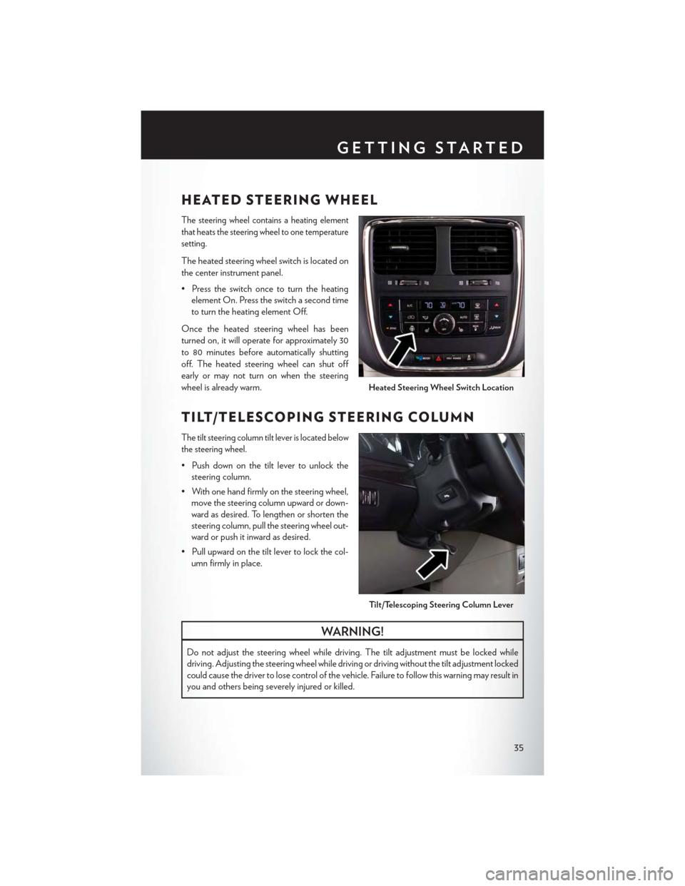
The heated steering wheel switch is located on
the center instrument panel.
• Press the switch once to turn the heating
element On. Press the switch a second time
to turn the heating element Off.
Once the heated steering wheel has been
turned on, it will operate for approximately 30
to 80 minutes before automatically shutting
off. The heated steering wheel can shut off
early or may not turn on when the steering
wheel is already warm.
TILT/TELESCOPING STEERING COLUMN
The tilt steering column tilt lever is located below
the steering wheel.
•Pushdownonthetiltlevertounlockthe
steering column.
• With one hand firmly on the steering wheel,
move the steering column upward or down-
ward as desired. To lengthen or shorten the
steering column, pull the steering wheel out-
ward or push it inward as desired.
•Pullupwardonthetiltlevertolockthecol-
umn firmly in place.
WARNING!
Do not adjust the steering wheel while driving. The tilt adjustment must be locked while
driving. Adjusting the steering wheel while driving or driving without the tilt adjustment locked
could cause the driver to lose control of the vehicle. Failure to follow this warning may result in
you and others being severely injured or killed.
Heated Steering Wheel Switch Location
Ti l t / Te l e s c o p i n g S t e e r i n g Co l u m n Le v e r
GETTING STARTED
35
Page 38 of 164

ADJUSTABLE PEDALS
• Press the switch located on the left side of
the steering column forward to move the
brake and accelerator pedals away from the
driver and press the switch rearward to move
the pedals closer to the driver.
NOTE:
The pedals cannot be adjusted when the vehicle
is in REVERSE or when the Electronic Speed
Control is set.
CAUTION!
Do not place any article under the adjustable pedals or impede its ability to move, as it may
cause damage to the pedal controls. Pedal travel may become limited if movement is stopped
by an obstruction in the adjustable pedal's path.
WARNING!
Do not adjust the pedals while the vehicle is moving. You could lose control and have a
collision. Always adjust the pedals while the vehicle is parked.
Adjustable Pedal Switch
GETTING STARTED
36
Page 44 of 164

To Decrease Speed
When the Electronic Speed Control is set, you can decrease speed by pushing the SET-button.
The drivers preferred units can be selected through the instrument panel settings if equipped.
Refer to “ Understanding Your Instrument Panel” for more information. The speed decrement
shown is dependant on the chosen speed unit of U.S. (MPH) or Metric (km/h):
U.S. Speed (MPH)
• Pushing the SET-button once will result in a 1 MPH decrease in set speed. Each
subsequent tap of the button results in a decrease of 1 MPH.
• If the button is continually pushed, the set speed will continue to decrease until the button
is released, then the new set speed will be established.
Metric Speed (km/h)
• Pushing the SET-button once will result in a 1 km/h decrease in set speed. Each
subsequent tap of the button results in a decrease of 1 km/h.
• If the button is continually pushed, the set speed will continue to decrease until the button
is released, then the new set speed will be established.
Resume
To resume a previously selected set speed in memory, push the RES + button and release.
Cancel
Push the CANCEL button, or apply the brakes to cancel the set speed and maintain the set
speed memory.
Push the ON/OFF button to turn the system off and erase the set speed memory.
WARNING!
•LeavingtheElectronicSpeedControlsystemonwhennotinuseisdangerous.Youcould
accidentally set the system or cause it to go faster than you want. You could lose control
and have a collision. Always leave the Electronic Speed Control system off when you are
not using it.
•ElectronicSpeedControlcanbedangerouswherethesystemcannotmaintainaconstant
speed. Your vehicle could go too fast for the conditions, and you could lose control. A
collision could be the result. Do not use Electronic Speed Control in heavy traffic or on
roads that are winding, icy, snow-covered or slippery.
OPERATING YOUR VEHICLE
42
Page 53 of 164
PA R K S E N S E ® R E A R PA R K A S S I S T
If an object is detected behind the rear bumper while the vehicle is in REVERSE, a warning will
display in the instrument cluster and a tone will sound, (closer the object the faster the tone) that
changes speed depending on the distance of the object from the bumper, will sound.
When the Instrument Cluster reads either “Clean Sensor” or “Blinded”, clean off the bumper
sensors to see if the condition is corrected.
PA R K V I E W ® R E A R B AC K- U P C A M E R A
Yo u c a n s e e a n o n - s c r e e n i m a g e o f t h e r e a r o f y o u r v e h i c l e w h e n e v e r t h e s h i f t l e v e r i s p u t i n t o
REVERSE. The ParkView® Rear Back-Up Camera image will be displayed on the radio display
screen, located on the center stack of the instrument panel.
If the radio display screen appears foggy, clean the camera lens located on the liftgate.
Refer to your Owner's Manual on the DVD for further details.
WARNING!
Drivers must be careful when backing up; even when using the ParkView® Rear Back-Up
Camera. Always check carefully behind your vehicle, and be sure to check for pedestrians,
animals, other vehicles, obstructions, or blind spots before backing up. You must continue to
pay attention while backing up. Failure to do so can result in serious injury or death.
BLIND SPOT MONITORING WITH REAR
CROSS PATH
The Blind Spot Monitoring (BSM) system uses two radar-based sensors, located inside the rear
bumper fascia, to detect Highway licensable vehicles (automobiles, trucks, motorcycles etc.) that
enter the blind spot zones from the rear/front/side of the vehicle.
The Blind Spot Monitoring (BSM) system warning light, located in the outside mirrors, will
illuminate if a vehicle moves into a blind spot zone.
The BSM system can also be configured to sound an audible (chime) alert and mute the radio to
notify you of objects that have entered the detection zones.
Refer to your Owner's Manual on the DVD for further details.
OPERATING YOUR VEHICLE
51
Page 56 of 164
Pinch Protection Feature
• This feature will detect an obstruction in the opening of the sunroof during Express Close
operation. If an obstruction in the path of the sunroof is detected, the sunroof will automati-
cally retract. Remove the obstruction if this occurs. Next, press the switch forward and release
to Express Close.
NOTE:
If three consecutive sunroof close attempts result in P inch Protect reversals, the fourth close
attempt will be a Manual Close movement with Pinch Protect disabled.
WARNING!
•Donotletchildrenplaywiththesunroof.Neverleavechildrenunattendedinavehicle,or
with access to an unlocked vehicle. Do not leave the Key Fob in or near the vehicle, and do
not leave the ignition of a vehicle equipped with Keyless Enter-N-Go™ in the ACC or
ON/RUN mode. Occupants, particularly unattended children, can become entrapped by
the power sunroof while operating the power sunroof switch. Such entrapment may result
in serious injury or death.
• In a collision, there is a greater risk of being thrown from a vehicle with an open sunroof.
Yo u c o u l d a l s o b e s e v e r e l y i n j u r e d o r k i l l e d . A l w a y s f a s t e n y o u r s e a t b e l t p r o p e r l y a n d m a k e
sure all passengers are properly secured.
•Donotallowsmallchildrentooperatethesunroof.Neverallowyourfingers,otherbody
parts, or any object to project through the sunroof opening. Injury may result.
OPERATING YOUR VEHICLE
54
Page 81 of 164
iPod®/USB/MP3 CONTROL
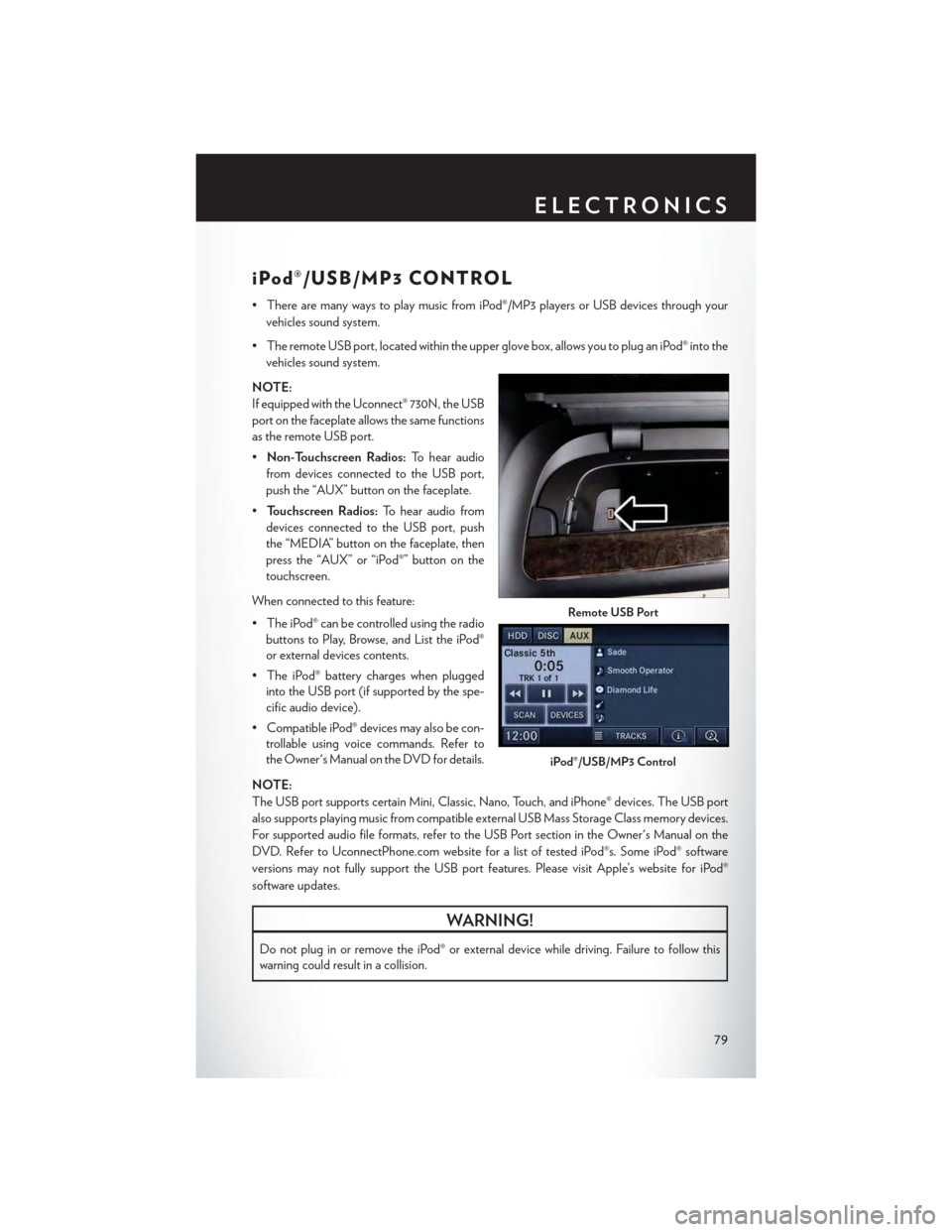
•TherearemanywaystoplaymusicfromiPod®/MP3playersorUSBdevicesthroughyour
vehicles sound system.
•TheremoteUSBport,locatedwithintheupperglovebox,allowsyoutopluganiPod®intothe
vehicles sound system.
NOTE:
If equipped with the Uconnect® 730N, the USB
port on the faceplate allows the same functions
as the remote USB port.
•Non-Touchscreen Radios:To hear audio
from devices connected to the USB port,
push the “AUX” button on the faceplate.
•To u c h s c r e e n R a d i o s :To hear audio from
devices connected to the USB port, push
the “MEDIA” button on the faceplate, then
press the “AUX” or “iPod®” button on the
touchscreen.
When connected to this feature:
• The iPod® can be controlled using the radio
buttons to Play, Browse, and List the iPod®
or external devices contents.
•TheiPod®batterychargeswhenplugged
into the USB port (if supported by the spe-
cific audio device).
•CompatibleiPod®devicesmayalsobecon-
trollable using voice commands. Refer to
the Owner's Manual on the DVD for details.
NOTE:
The USB port supports certain Mini, Classic, Nano, Touch, and iPhone® devices. The USB port
also supports playing music from compatible external USB Mass Storage Class memory devices.
For supported audio file formats, refer to the USB Port section in the Owner's Manual on the
DVD. Refer to UconnectPhone.com website for a list of tested iPod®s. Some iPod® software
versions may not fully support the USB port features. Please visit Apple’s website for iPod®
software updates.
WARNING!
Do not plug in or remove the iPod® or external device while driving. Failure to follow this
warning could result in a collision.
Remote USB Port
iPod®/USB/MP3 Control
ELECTRONICS
79