wheel CHRYSLER TOWN AND COUNTRY 2015 5.G Owner's Manual
[x] Cancel search | Manufacturer: CHRYSLER, Model Year: 2015, Model line: TOWN AND COUNTRY, Model: CHRYSLER TOWN AND COUNTRY 2015 5.GPages: 164, PDF Size: 22.47 MB
Page 89 of 164
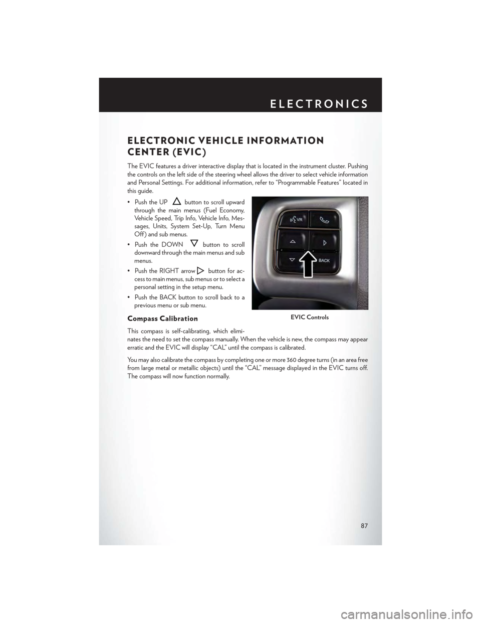
ELECTRONIC VEHICLE INFORMATION
CENTER (EVIC)
The EVIC features a driver interactive display that is located in the instrument cluster. Pushing
the controls on the left side of the steering wheel allows the driver to select vehicle information
and Personal Settings. For additional information, refer to “Programmable Features” located in
this guide.
• Push the UPbutton to scroll upward
through the main menus (Fuel Economy,
Vehicle Speed, Trip Info, Vehicle Info, Mes-
sages, Units, System Set-Up, Turn Menu
Off ) and sub menus.
• Push the DOWNbutton to scroll
downward through the main menus and sub
menus.
• Push the RIGHT arrowbutton for ac-
cess to main menus, sub menus or to select a
personal setting in the setup menu.
•PushtheBACKbuttontoscrollbacktoa
previous menu or sub menu.
Compass Calibration
This compass is self-calibrating, which elimi-
nates the need to set the compass manually. When the vehicle is new, the compass may appear
erratic and the EVIC will display “CAL” until the compass is calibrated.
Yo u m a y a l s o c a l i b r a t e t h e c o m p a s s b y c o m p l e t i n g o n e o r m o r e 3 6 0 d e g r e e t u r n s ( i n a n a r e a f r e e
from large metal or metallic objects) until the “CAL” message displayed in the EVIC turns off.
The compass will now function normally.
EVIC Controls
ELECTRONICS
87
Page 99 of 164

RECREATIONAL TOWING
(BEHIND MOTORHOME, ETC.)
Towing Condition Wheels OFF the GroundAll Models
Flat TowNONENOT ALLOWED
Dolly TowFrontOK
RearNOT ALLOWED
On TrailerALLOK
Recreational Towing — All Models
Recreational towing is allowed ONLY if the front wheels are OFF the ground. This may be
accomplished using a tow dolly or vehicle trailer. If using a tow dolly, follow this procedure:
1. Properly secure the dolly to the tow vehicle, following the dolly manufacturer's instructions.
2. Drive the front wheels onto the tow dolly.
3. Firmly apply the parking brake. Place the transmission in PARK.
4. Properly secure the front wheels to the dolly, following the dolly manufacturer's instructions.
5. Release the parking brake.
CAUTION!
•DONOTflattowthisvehicle.Damagetothedrivetrainwillresult.
•Towingthisvehicleinviolationoftheaboverequirementscancauseseveretransmission
damage. Damage from improper towing is not covered under the New Vehicle Limited
Warranty.
UTILITY
97
Page 101 of 164
If the light remains lit with the engine running, your vehicle will usually be drivable; however, see
an authorized dealer immediately. If the light is flashing when the engine is running, immediate
service is required and you may experience reduced performance, an elevated/rough idle or
engine stall and your vehicle may require towing.
-TirePressureMonitoringSystem(TPMS)Light
Each tire, including the spare (if provided), should be checked monthly when cold and inflated to
the inflation pressure recommended by the vehicle manufacturer on the vehicle placard or tire
inflation pressure label. (If your vehicle has tires of a different size than the size indicated on the
vehicle placard or tire inflation pressure label, you should determine the proper tire inflation
pressure for those tires.)
As an added safety feature, your vehicle has been equipped with a tire pressure monitoring
system (TPMS) that illuminates a low tire pressure telltale when one or more of your tires is
significantly under-inflated. Accordingly, when the low tire pressure telltale illuminates, you
should stop and check your tires as soon as possible, and inflate them to the proper pressure.
Driving on a significantly under-inflated tire causes the tire to overheat and can lead to tire failure.
Under-inflation also reduces fuel efficiency and tire tread life, and may affect the vehicle’s
handling and stopping ability.
IF THE LIGHT STARTS FLASHING INDICATING A LOW TIRE PRESSURE, ADJUST
THE AIR PRESSURE IN THE LOW TIRE TO THE AIR PRESSURE SHOWN ON THE
VEHICLE PLACARD OR TIRE INFLATION PRESSURE LABEL LOCATED ON THE
DRIVER'S DOOR.
NOTE:
AFTER INFLATION, THE VEHICLE MAY NEED TO BE DRIVEN FOR 20 MINUTES
BEFORE THE FLASHING LIGHT WILL TURN OFF.
Please note that the TPMS is not a substitute for proper tire maintenance, and it is the driver’s
responsibility to maintain correct tire pressure, even if under-inflation has not reached the level to
trigger illumination of the TPMS low tire pressure telltale.
Yo u r v e h i c l e h a s a l s o b e e n e q u i p p e d w i t h a T P M S m a l f u n c t i o n i n d i c a t o r t o i n d i c a t e w h e n t h e
system is not operating properly. The TPMS malfunction indicator is combined with the low tire
pressure telltale.
When the system detects a malfunction, the telltale will flash for approximately one minute and
then remain continuously illuminated. This sequence will continue upon subsequent vehicle
start-ups as long as the malfunction exists. When the malfunction indicator is illuminated, the
system may not be able to detect or signal low tire pressure as intended. TPMS malfunctions may
occur for a variety of reasons, including the installation of replacement or alternate tires or wheels
on the vehicle that prevent the TPMS from functioning properly. Always check the TPMS
malfunction telltale after replacing one or more tires or wheels on your vehicle to ensure that the
replacement or alternate tires and wheels allow the TPMS to continue to function properly.
WHAT TO DO IN EMERGENCIES
99
Page 102 of 164
NOTE:
Tire pressures change by approximately 1 psi (7 kPa) per 12° F (7° C) of air temperature change.
Keep this in mind when checking tire pressure inside a garage, especially in the Winter. Example:
If garage temperature is 68°F (20°C) and the outside temperature is 32°F (0°C), then the cold
tire inflation pressure should be increased by 3 psi (21 kPa), which equals 1 psi (7 kPa) for every
12°F (7°C) for this outside temperature condition.
CAUTION!
The TPMS has been optimized for the original equipment tires and wheels. TPMS pressures
and warning have been established for the tire size equipped on your vehicle. Undesirable
system operation or sensor damage may result when using replacement equipment that is not
of the same size, type, and/or style. Aftermarket wheels can cause sensor damage. Do not use
tire sealant from a can, or balance beads if your vehicle is equipped with a TPMS, as damage
to the sensors may result.
-EngineTemperatureWarningLight
•Thislightwarnsofanoverheatedenginecondition.
•Ifthelightturnsonorflashescontinuouslywhiledriving,safelypulloverandstopthevehicle.
If the A/C system is on, turn it off. Also, shift the transmission into NEUTRAL and idle the
vehicle. If the temperature reading does not return to normal, turn the engine off immediately
and call for service.
•Werecommendthatyoudonotoperatethevehicleorenginedamagewilloccur.Havethe
vehicle serviced immediately.
WARNING!
Ahotenginecoolingsystemisdangerous.Youorotherscouldbebadlyburnedbysteamor
boiling coolant.
-SeatBeltReminderLight
When the ignition switch is first turned to the ON/RUN position, this light will turn on for four to
eight seconds as a bulb check. During the bulb check, if the driver's seat belt is unbuckled, a
chime will sound. After the bulb check or when driving, if the driver or front passenger seat belt
remains unbuckled, the Seat Belt Indicator Light will flash or remain on continuously. Refer to
“Seat Belt Systems” in “Things To Know Before Starting” in the OM on your DVD for further
information.
-BrakeWarningLight
This light monitors various brake functions, including brake fluid level and parking brake appli-
cation. If the brake light turns on it may indicate that the parking brake is applied, that the brake
fluid level is low, or that there is a problem with the anti-lock brake system reservoir.
WHAT TO DO IN EMERGENCIES
100
Page 107 of 164
Ti re S e r v i c e K i t S t o ra g e
•TheTireServiceKitisstowedbehindtherearleftsidetrimpanelintherearcargoarea.
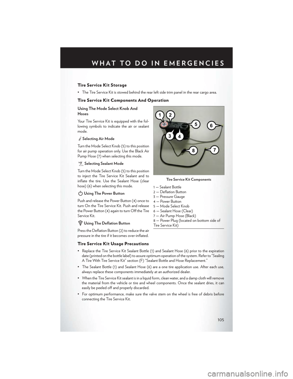
Ti re S e r v i c e K i t Co m p o n e n t s A n d O p e ra t i o n
Using The Mode Select Knob And
Hoses
Your Tire Service Kit is equipped with the fol-
lowing symbols to indicate the air or sealant
mode.
Selecting Air Mode
Tu r n t h e M o d e S e l e c t K n o b ( 5 ) t o t h i s p o s i t i o n
for air pump operation only. Use the Black Air
Pump Hose (7) when selecting this mode.
Selecting Sealant Mode
Tu r n t h e M o d e S e l e c t K n o b ( 5 ) t o t h i s p o s i t i o n
to inject the Tire Service Kit Sealant and to
inflate the tire. Use the Sealant Hose (clear
hose) (6) when selecting this mode.
Using The Power Button
Push and release the Power Button (4) once to
turn On the Tire Service Kit. Push and release
the Power Button (4) again to turn Off the Tire
Service Kit.
Using The Deflation Button
Press the Deflation Button (2) to reduce the air
pressure in the tire if it becomes over-inflated.
Ti re S e r v i c e K i t Us a g e Pre c a u t i o n s
• Replace the Tire Service Kit Sealant Bottle (1) and Sealant Hose (6) prior to the expiration
date (printed on the bottle label) to assure optimum operation of the system. Refer to “Sealing
A Tire With Tire Service Kit” section (F) “Sealant Bottle and Hose Replacement.”
• The Sealant Bottle (1) and Sealant Hose (6) are a one tire application use. After each use,
always replace these components immediately at an authorized dealer.
•WhentheTireServiceKitsealantisinaliquidform,cleanwater,andadampclothwillremove
the material from the vehicle or tire and wheel components. Once the sealant dries, it can
easily be peeled off and properly discarded.
•Foroptimumperformance,makesurethevalvestemonthewheelisfreeofdebrisbefore
connecting the Tire Service Kit.
Ti re S e r v i c e K i t Co m p o n e n t s
1 — Sealant Bottle2 — Deflation Button3 — Pressure Gauge4 — Power Button5—ModeSelectKnob6 — Sealant Hose (Clear)7 — Air Pump Hose (Black)8 — Power Plug (located on bottom side ofTire Service Kit)
WHAT TO DO IN EMERGENCIES
105
Page 108 of 164
•YoucanusetheTireServiceKitairpumptoinflatebicycletires.Thekitalsocomeswithtwo
needles, located in the Accessory Storage Compartment (on the bottom of the air pump) for
inflating sport balls, rafts, or similar inflatable items. However, use only the Air Pump Hose (7)
and make sure the Mode Select Knob (5) is in the Air Mode when inflating such items to avoid
injecting sealant into them. The Tire Service Kit Sealant is only intended to seal punctures less
than 1/4 inch (6 mm) diameter in the tread of your vehicle.
• Do not lift or carry the Tire Service Kit by the hoses.
Sealing A Tire With Tire Service Kit
(A) Whenever You Stop To Use Tire Service Kit:
1. Pull over to a safe location and turn on the vehicle’s Hazard Warning flashers.
2. Verify that the valve stem (on the wheel with the deflated tire) is in a position that is near to the
ground. This will allow the Tire Service Kit Hoses (6) and (7) to reach the valve stem and keep
the Tire Service Kit flat on the ground. This will provide the best positioning of the kit when
injecting the sealant into the deflated tire and running the air pump. Move the vehicle as
necessary to place the valve stem in this position before proceeding.
3. Place the transmission in PARK (auto transmission) or in Gear (manual transmission) and
cycle the ignition to the OFF position.
4. Set the parking brake.
(B) Setting Up To Use Tire Service Kit:
1. Turn the Mode Select Knob (5) to the Sealant Mode position.
2. Uncoil the Sealant Hose (6) and then remove the cap from the fitting at the end of the hose.
3. Place the Tire Service Kit flat on the ground next to the deflated tire.
4. Remove the cap from the valve stem and then screw the fitting at the end of the Sealant Hose
(6) onto the valve stem.
5. Uncoil the Power Plug (8) and insert the plug into the vehicle’s 12 Volt power outlet.
6. Do not remove foreign objects (e.g., screws or nails) from the tire.
(C) Injecting Tire Service Kit Sealant Into The Deflated Tire:
Always start the engine before turning ON the Tire Service Kit.
NOTE:
Manual transmission vehicles must have the parking brake engaged and the shift lever in
NEUTRAL.
After pressing the Power Button (4), the sealant (white fluid) will flow from the Sealant Bottle (1)
through the Sealant Hose (6) and into the tire.
NOTE:
Sealant may leak out through the puncture in the tire.
WHAT TO DO IN EMERGENCIES
106
Page 111 of 164
6. Verify that the cap is installed on the fitting at the end of the Sealant Hose (6) and return the
hose to its storage area (located on the bottom of the air pump).
7. Return the Tire Service Kit to its storage location in the vehicle.
NOTE:
•The metal end fitting from Power Plug (8) may get hot after use, so it should be handled carefully.
• Failure to reinstall the cap on the fitting at the end of the Sealant Hose (6) can result in sealant
contacting your skin, clothing, and the vehicle’s interior. It can also result in sealant contacting
internal Tire Service Kit components which may cause permanent damage to the kit.
WARNING!
•Donotattempttosealatireonthesideofthevehicleclosesttotraffic.Pullfarenoughoff
the road to avoid the danger of being hit when using the Tire Service Kit.
•DonotusetheTireServiceKitordrivethevehicleunderthefollowingcircumstances:
• If the puncture in the tire tread is approximately 1/4”. (6 mm) or larger.
• If the tire has any sidewall damage.
• If the tire has any damage from driving with extremely low tire pressure.
• If the tire has any damage from driving on a flat tire.
• If the wheel has any damage.
• If you are unsure of the condition of the tire or the wheel.
• Keep the Tire Service Kit away from open flames or heat source.
• A loose Tire Service Kit thrown forward in a collision or hard stop could endanger the
occupants of the vehicle. Always stow the Tire Service Kit in the place provided. Failure to
follow these warnings can result in injuries that are serious or fatal to you, your passengers,
and others around you.
•Ta k e c a r e n o t t o a l l o w t h e c o n t e n t s o f t h e T i r e S e r v i c e K i t t o c o m e i n c o n t a c t w i t h h a i r , e y e s ,
or clothing. The Tire Service Kit is harmful if inhaled, swallowed, or absorbed through the skin.
It causes skin, eye, and respiratory irritation. Flush immediately with plenty of water if there is
any contact with eyes or skin. Change clothing as soon as possible, if there is any contact with
clothing.
• The Tire Service Kit Sealant solution contains latex. In case of an allergic reaction or rash,
consult a physician immediately. Keep the Tire Service Kit out of reach of children.
If swallowed, rinse mouth immediately with plenty of water and drink plenty of water.
Do not induce vomiting! Consult a physician immediately.
•TheTireServiceKitisnotapermanentflattirerepair.Havethetireinspectedandrepaired
or replaced after using the Tire Service Kit. Do not exceed 55 mph (88 km/h) until the tire
is repaired or replaced. Failure to follow this warning can result in injuries that are serious or
fatal to you, your passengers, and others around you.
WHAT TO DO IN EMERGENCIES
109
Page 117 of 164
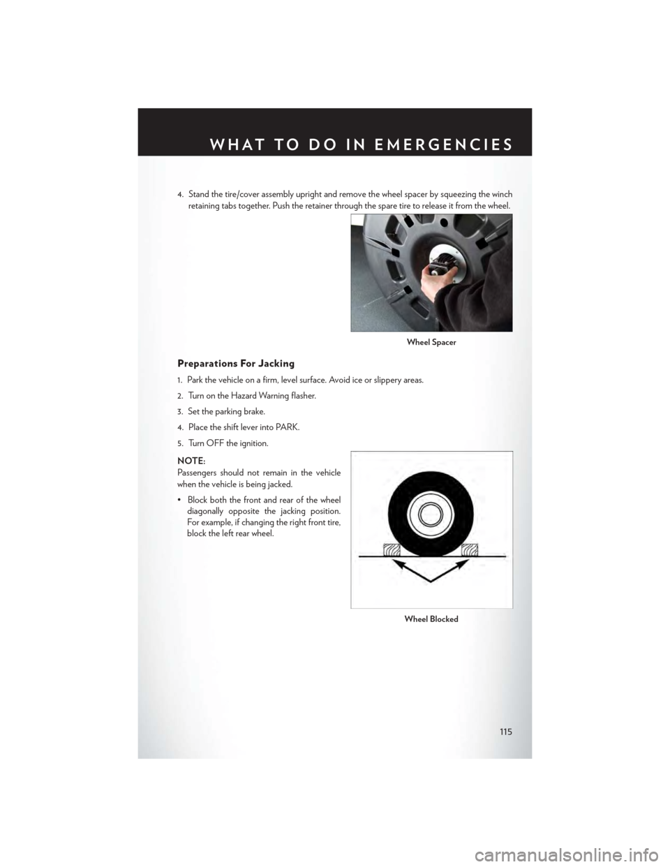
4. Stand the tire/cover assembly upright and remove the wheel spacer by squeezing the winch
retaining tabs together. Push the retainer through the spare tire to release it from the wheel.
Preparations For Jacking
1. Park the vehicle on a firm, level surface. Avoid ice or slippery areas.
2. Turn on the Hazard Warning flasher.
3. Set the parking brake.
4. Place the shift lever into PARK.
5. Turn OFF the ignition.
NOTE:
Passengers should not remain in the vehicle
when the vehicle is being jacked.
• Block both the front and rear of the wheel
diagonally opposite the jacking position.
For example, if changing the right front tire,
block the left rear wheel.
Wheel Spacer
Wheel Blocked
WHAT TO DO IN EMERGENCIES
115
Page 118 of 164

Jacking Instructions
1. Loosen (but do not remove) the wheel lug
nuts by turning them to the left one turn
while the wheel is still on the ground.
2. There are two jack engagement locations on each side of the vehicle body. These locations are
on the sill flange of the vehicle body.
Warning Label
Jack Engagement Locations
WHAT TO DO IN EMERGENCIES
116
Page 119 of 164

Rear jack locations are between a pair of down-facing tabs on the sill flange of the vehicle
side body.
Front jack location is on the sill flange of the vehicle body and is located 6 in (150 mm) from
door edge.
NOTE:
In some situations the jack may need to be
placed on its side in order to be pushed under
the vehicle. Return the jack to its correct orien-
tation once it is under the vehicle.
3. Place the wrench on the jack screw and turn to the right until the jack head is properly engaged
in the described location.Do not raise the vehicle until you are sure the jack is securely
engaged.
4. Raise the vehicle by turning the jack screw to the right, using the swivel wrench. Raise the
vehicle only until the tire just clears the surface and enough clearance is obtained to install the
spare tire. Minimum tire lift provides maximum stability.
5. Remove the wheel lug nuts, for vehicles with wheel covers, remove the cover from the wheel
by hand. Do not pry the wheel cover off. Then pull the wheel off the hub.
Rear Jacking Location Engaged
Front Jacking Location Engaged
WHAT TO DO IN EMERGENCIES
117