ignition CHRYSLER TOWN AND COUNTRY 2015 5.G Owner's Manual
[x] Cancel search | Manufacturer: CHRYSLER, Model Year: 2015, Model line: TOWN AND COUNTRY, Model: CHRYSLER TOWN AND COUNTRY 2015 5.GPages: 164, PDF Size: 22.47 MB
Page 117 of 164
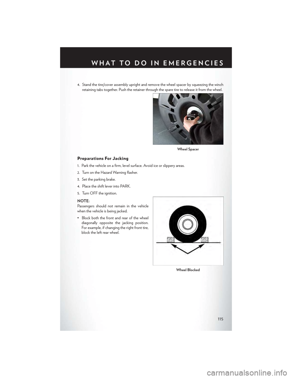
4. Stand the tire/cover assembly upright and remove the wheel spacer by squeezing the winch
retaining tabs together. Push the retainer through the spare tire to release it from the wheel.
Preparations For Jacking
1. Park the vehicle on a firm, level surface. Avoid ice or slippery areas.
2. Turn on the Hazard Warning flasher.
3. Set the parking brake.
4. Place the shift lever into PARK.
5. Turn OFF the ignition.
NOTE:
Passengers should not remain in the vehicle
when the vehicle is being jacked.
• Block both the front and rear of the wheel
diagonally opposite the jacking position.
For example, if changing the right front tire,
block the left rear wheel.
Wheel Spacer
Wheel Blocked
WHAT TO DO IN EMERGENCIES
115
Page 124 of 164
JUMP-STARTING
If your vehicle has a discharged battery it can be jump-started using a set of jumper cables and a
battery in another vehicle or by using a portable battery booster pack.
Jump-starting can be dangerous if done improperly so please follow the procedures in this
section carefully.
NOTE:
When using a portable battery booster pack
follow the manufacturer’s operating instruc-
tions and precautions.
Preparations For Jump-Start
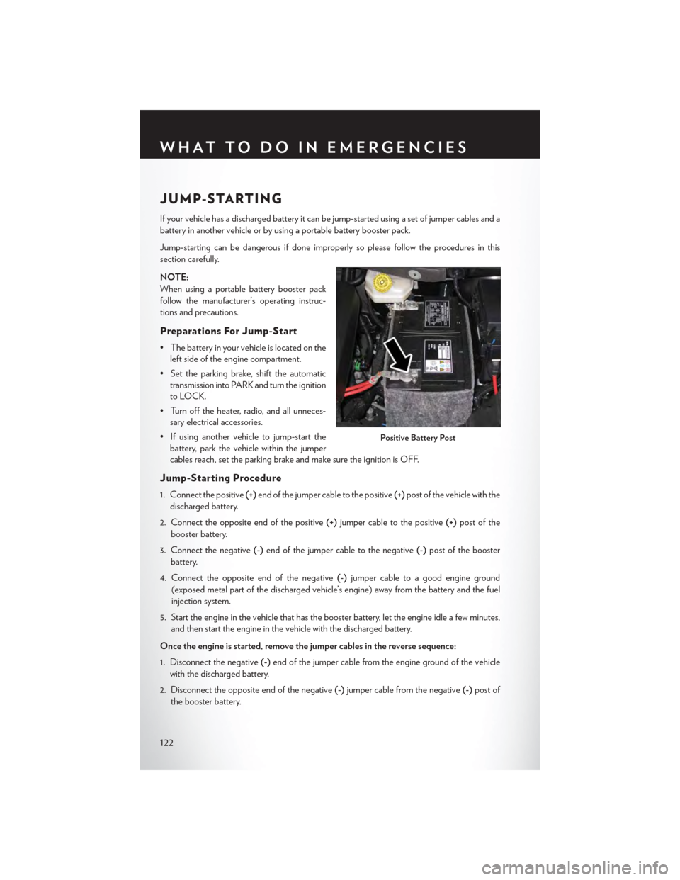
•Thebatteryinyourvehicleislocatedonthe
left side of the engine compartment.
•Settheparkingbrake,shifttheautomatic
transmission into PARK and turn the ignition
to LOCK.
• Turn off the heater, radio, and all unneces-
sary electrical accessories.
•Ifusinganothervehicletojump-startthe
battery, park the vehicle within the jumper
cables reach, set the parking brake and make sure the ignition is OFF.
Jump-Starting Procedure
1. Connect the positive(+)end of the jumper cable to the positive(+)post of the vehicle with the
discharged battery.
2. Connect the opposite end of the positive(+)jumper cable to the positive(+)post of the
booster battery.
3. Connect the negative(-)end of the jumper cable to the negative(-)post of the booster
battery.
4. Connect the opposite end of the negative(-)jumper cable to a good engine ground
(exposed metal part of the discharged vehicle’s engine) away from the battery and the fuel
injection system.
5. Start the engine in the vehicle that has the booster battery, let the engine idle a few minutes,
and then start the engine in the vehicle with the discharged battery.
Once the engine is started, remove the jumper cables in the reverse sequence:
1. Disconnect the negative(-)end of the jumper cable from the engine ground of the vehicle
with the discharged battery.
2. Disconnect the opposite end of the negative(-)jumper cable from the negative(-)post of
the booster battery.
Positive Battery Post
WHAT TO DO IN EMERGENCIES
122
Page 125 of 164
3. Disconnect the positive(+)end of the jumper cable from the positive(+)post of the booster
battery.
4. Disconnect the opposite end of the positive(+)jumper cable from the positive(+)post of the
vehicle with the discharged battery.
NOTE:
If frequent jump-starting is required to start your vehicle you should have the battery and
charging system inspected at your authorized dealer.
CAUTION!
•Donotuseaportablebatteryboosterpackoranyotherboostersourcewithasystem
voltage greater than 12 Volts or damage to the battery, starter motor, alternator or
electrical system may occur.
•Failuretofollowtheseprocedurescouldresultindamagetothechargingsystemofthe
booster vehicle or the discharged vehicle.
•Accessoriesthatcanbepluggedintothevehiclepoweroutletsdrawpowerfromthe
vehicle’s battery, even when not in use (e.g., cellular phones, etc.). Eventually, if plugged in
long enough, the vehicle’s battery discharges sufficiently to degrade battery life and/or
prevent the engine from starting.
WARNING!
•Whentemperaturesarebelowthefreezingpoint,electrolyteinadischargedbatterymay
freeze. Do not attempt jump-starting because the battery could rupture or explode and
cause personal injury. Battery temperature must be brought above the freezing point
before attempting a jump-start.
•Takecaretoavoidtheradiatorcoolingfanwheneverthehoodisraised.Itcanstartanytime
the ignition switch is on. You can be injured by moving fan blades.
•Removeanymetaljewelry,suchaswatchbandsorbracelets,thatmightmakean
inadvertent electrical contact. You could be severely injured.
•Batteriescontainsulfuricacidthatcanburnyourskinoreyesandgeneratehydrogengas
which is flammable and explosive. Keep open flames or sparks away from the battery.
•Donotallowvehiclestotoucheachotherasthiscouldestablishagroundconnectionand
personal injury could result.
• Failure to follow this procedure could result in personal injury or property damage due to
battery explosion.
•Donotconnectthecabletothenegativepost(-)ofthedischargedbattery.Theresulting
electrical spark could cause the battery to explode and could result in personal injury.
WHAT TO DO IN EMERGENCIES
123
Page 126 of 164

SHIFT LEVER OVERRIDE
If a malfunction occurs and the shift lever can-
not be moved out of the PARK position, you
can use the following procedure to temporarily
move the shift lever:
1. To access the shift lever override, remove
the cover located to the top right of the shift
lever in the instrument panel.
2. Firmly set the parking brake.
3. Turn the ignition switch to the ACC or ON
position without starting the engine.
4. Press and maintain firm pressure on the
brake pedal.
5.The override can be activated by pressing the
white-colored tab, which can be accessed
through the hole in the instrument panel.
6. Move the shift lever into the NEUTRAL position.
7. The vehicle may then be started in NEUTRAL.
8. Reinstall the override cover.
TOWING A DISABLED VEHICLE
To w i n g C o n d i t i o n W h e e l s O F F t h e G r o u n d A L L M O D E L S
Flat TowNONEIf transmission is operable:• Transmission inNEUTRAL•25 mph (40 km/h)maxspeed•15 miles (24 km)maxdistanceWheel liftRear
FrontOK
FlatbedALLBEST METHOD
Shift Lever Override
WHAT TO DO IN EMERGENCIES
124
Page 140 of 164
To t a l l y I n t e g r a t e d P o w e r M o d u l e ( F u s e s )
The Totally Integrated Power Module is located in the engine compartment near the battery.
Refer to the applicable “Engine Compartment” illustration in this section. This center contains
cartridge fuses and mini-fuses. A label that identifies each component may be printed or
embossed on the inside of the cover.
CAUTION!
•WheninstallingtheTotallyIntegratedPowerModulecover,itisimportanttoensurethe
cover is properly positioned and fully latched. Failure to do so may allow water to get into
the Integrated Power Module, and possibly result in a electrical system failure.
• When replacing a blown fuse, it is important to use only a fuse having the correct
amperage rating. The use of a fuse with a rating other than indicated may result in a
dangerous electrical system overload. If a properly rated fuse continues to blow, it
indicates a problem in the circuit that must be corrected.
The numbers inside the TIPM cover correspond to the following table.
Cavity Cartridge Fuse Mini-FuseDescription
J1 40 Amp Green–Power Folding Seat
J2 30 Amp Pink–Power Liftgate Module
J3 30 Amp Pink–Rear Door Module
J4 25 Amp Clear–Driver Door Node
J5 25 Amp Clear–Passenger Door Node
J6 40 Amp Green–Antilock Brakes Pump/StabilityControl System
J7 30 Amp Pink–Antilock Brakes Valve/StabilityControl System
J8 40 Amp Green–Power Memory Seat – If Equipped
J9 40 Amp Green–Partial Zero Emissions Vehicle Motor/Flex Fuel – If Equipped
J10 30 Amp Pink–Headlamp Wash/Manifold TuningVa l v e – I f E q u i p p e d
J11 30 Amp Pink–Power Sliding Door Module/Anti-TheftModule – If Equipped
J12 30 Amp Pink– HVAC Rear Blower, Radiator Fan Motor
J13 60 Amp Yellow–Ignition Off Draw (IOD) – Main
J14 40 Amp Green–Rear Window Defogger
J15 40 Amp Green–Front Blower
J17 40 Amp Green–Starter Solenoid
J18 20 Amp Blue–PowertrainControlModuleTransRange
J19 60 Amp Yellow–Radiator Fan
MAINTAINING YOUR VEHICLE
138
Page 141 of 164
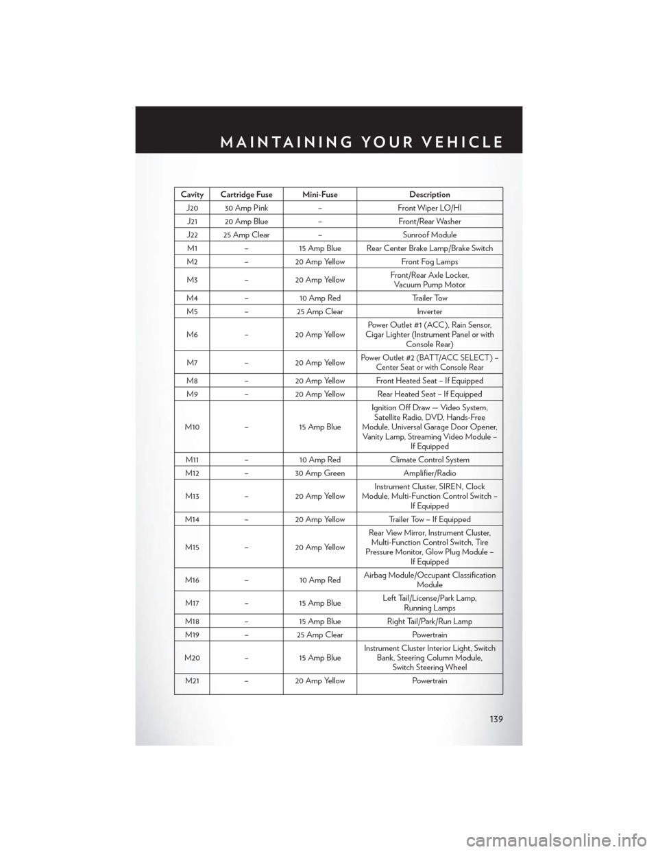
Cavity Cartridge Fuse Mini-FuseDescription
J20 30 Amp Pink–Front Wiper LO/HI
J21 20 Amp Blue–Front/Rear Washer
J22 25 Amp Clear–Sunroof Module
M1–15 Amp Blue Rear Center Brake Lamp/Brake Switch
M2–20 Amp YellowFront Fog Lamps
M3–20 Amp YellowFront/Rear Axle Locker,Vacuum Pump Motor
M4–10 Amp RedTr a i l e r To w
M5–25 Amp ClearInverter
M6–20 Amp YellowPower Outlet #1 (ACC ), Rain Sensor,Cigar Lighter (Instrument Panel or withConsole Rear)
M7–20 Amp YellowPower Outlet #2 (BATT/ACC SELECT ) –Center Seat or with Console Rear
M8–20 Amp Yellow Front Heated Seat – If Equipped
M9–20 Amp Yellow Rear Heated Seat – If Equipped
M10–15 Amp Blue
Ignition Off Draw — Video System,Satellite Radio, DVD, Hands-FreeModule, Universal Garage Door Opener,Vanity Lamp, Streaming Video Module –If Equipped
M11–10 Amp RedClimate Control System
M12–30 Amp GreenAmplifier/Radio
M13–20 Amp YellowInstrument Cluster, SIREN, ClockModule, Multi-Function Control Switch –If Equipped
M14–20 Amp YellowTrailer Tow – If Equipped
M15–20 Amp Yellow
Rear View Mirror, Instrument Cluster,Multi-Function Control Switch, TirePressure Monitor, Glow Plug Module –If Equipped
M16–10 Amp RedAirbag Module/Occupant ClassificationModule
M17–15 Amp BlueLeft Tail/License/Park Lamp,Running Lamps
M18–15 Amp BlueRight Tail/Park/Run Lamp
M19–25 Amp ClearPowertrain
M20–15 Amp BlueInstrument Cluster Interior Light, SwitchBank, Steering Column Module,Switch Steering Wheel
M21–20 Amp YellowPowertrain
MAINTAINING YOUR VEHICLE
139