tow CHRYSLER TOWN AND COUNTRY 2015 5.G Owner's Manual
[x] Cancel search | Manufacturer: CHRYSLER, Model Year: 2015, Model line: TOWN AND COUNTRY, Model: CHRYSLER TOWN AND COUNTRY 2015 5.GPages: 164, PDF Size: 22.47 MB
Page 120 of 164
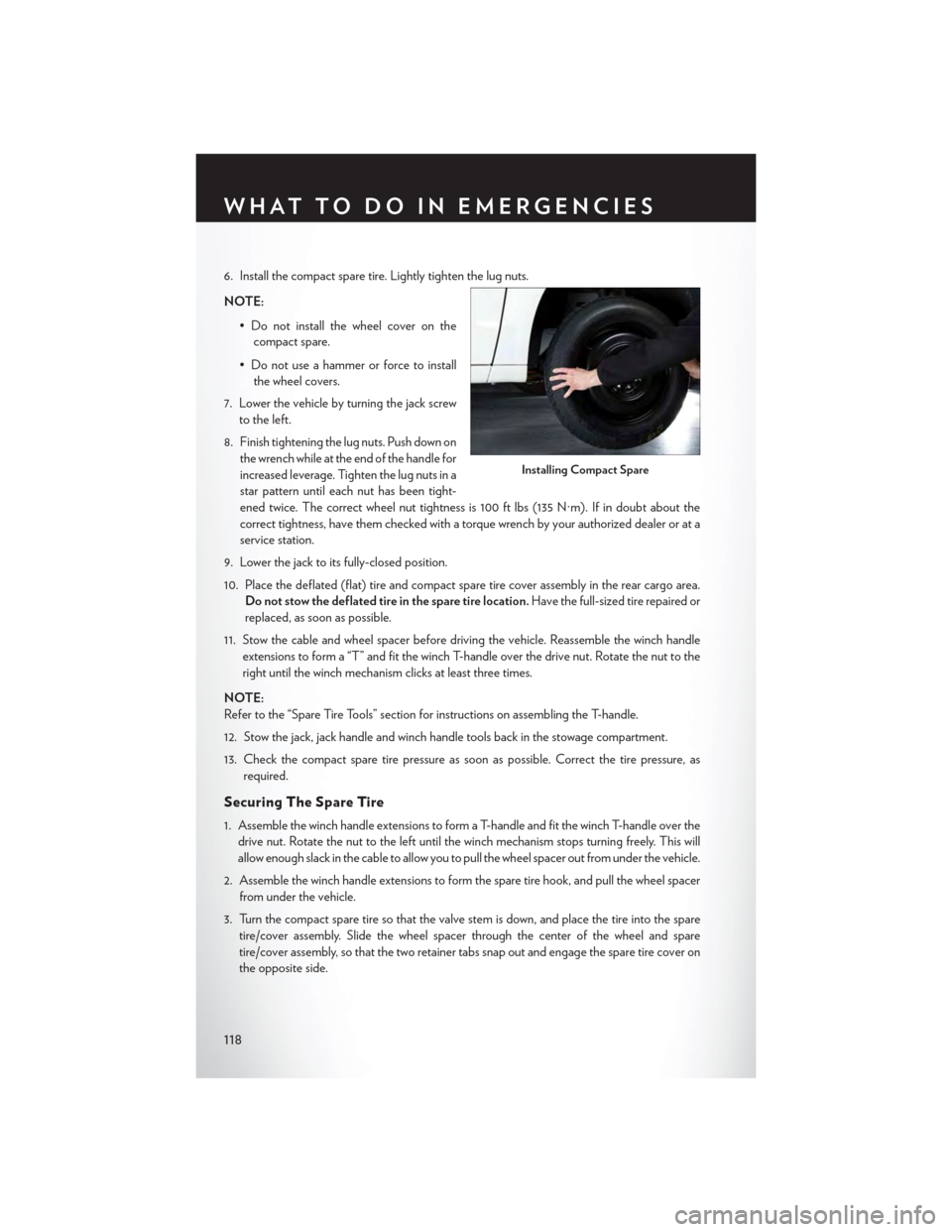
6. Install the compact spare tire. Lightly tighten the lug nuts.
NOTE:
•Donotinstallthewheelcoveronthe
compact spare.
• Do not use a hammer or force to install
the wheel covers.
7. Lower the vehicle by turning the jack screw
to the left.
8. Finish tightening the lug nuts. Push down on
the wrench while at the end of the handle for
increased leverage. Tighten the lug nuts in a
star pattern until each nut has been tight-
ened twice. The correct wheel nut tightness is 100 ft lbs (135 N·m). If in doubt about the
correct tightness, have them checked with a torque wrench by your authorized dealer or at a
service station.
9. Lower the jack to its fully-closed position.
10. Place the deflated (flat) tire and compact spare tire cover assembly in the rear cargo area.
Do not stow the deflated tire in the spare tire location.Have the full-sized tire repaired or
replaced, as soon as possible.
11. Stow the cable and wheel spacer before driving the vehicle. Reassemble the winch handle
extensions to form a “T” and fit the winch T-handle over the drive nut. Rotate the nut to the
right until the winch mechanism clicks at least three times.
NOTE:
Refer to the “Spare Tire Tools” section for instructions on assembling the T-handle.
12. Stow the jack, jack handle and winch handle tools back in the stowage compartment.
13. Check the compact spare tire pressure as soon as possible. Correct the tire pressure, as
required.
Securing The Spare Tire
1. Assemble the winch handle extensions to form a T-handle and fit the winch T-handle over the
drive nut. Rotate the nut to the left until the winch mechanism stops turning freely. This will
allow enough slack in the cable to allow you to pull the wheel spacer out from under the vehicle.
2. Assemble the winch handle extensions to form the spare tire hook, and pull the wheel spacer
from under the vehicle.
3. Turn the compact spare tire so that the valve stem is down, and place the tire into the spare
tire/cover assembly. Slide the wheel spacer through the center of the wheel and spare
tire/cover assembly, so that the two retainer tabs snap out and engage the spare tire cover on
the opposite side.
Installing Compact Spare
WHAT TO DO IN EMERGENCIES
118
Page 121 of 164

4. Using the winch T-handle, rotate the drive nut to the right until the compact spare tire/cover
assembly is drawn into place against the underside of the vehicle.
5. Continue to rotate the nut to the right until you hear the winch mechanism click three times.
It cannot be overtightened. Check under the vehicle to ensure the compact spare tire/cover
assembly is positioned correctly against the underside of the vehicle.
Road Tire Installation
Ve h i c l e s E q u i p p e d W i t h W h e e l C o v e r s
1. Mount the road tire on the axle.
2. To ease the installation process for steel wheels with wheel covers, install two lug nuts on the
mounting studs which are on each side of the valve stem. Install the lug nuts with the cone
shaped end of the nut toward the wheel. Lightly tighten the lug nuts.
3. Align the valve notch in the wheel cover with
the valve stem on the wheel. Install the cover
by hand, snapping the cover over the two
lug nuts. Do not use a hammer or excessive
force to install the cover.
4. Install the remaining lug nuts with the cone
shaped end of the nut toward the wheel.
Lightly tighten the lug nuts.
5. Lower the vehicle to the ground by turning
the jack handle counterclockwise.
6. Finish tightening the lug nuts. Push down on
the wrench while at the end of the handle for
increased leverage. Tighten the lug nuts in a
star pattern until each nut has been tight-
ened twice. The correct tightness of each
lug nut is 100 ft/lbs (135 N·m). If in doubt
about the correct tightness, have them
checked with a torque wrench by your au-
thorized dealer or service station.
7. After 25 miles (40 km) check the lug nut torque with a torque wrench to ensure that all lug nuts
are properly seated against the wheel.
Wheel Cover Installation
1—ValveStem2—ValveNotch3—WheelLugNut4—WheelCover5—MountingStud
WHAT TO DO IN EMERGENCIES
119
Page 122 of 164
Ve h i c l e s W i t h o u t W h e e l C o v e r s
1. Mount the road tire on the axle.
2. Install the remaining lug nuts with the cone shaped end of the nut toward the wheel. Lightly
tighten the lug nuts.
3. Lower the vehicle to the ground by turning the jack handle counterclockwise.
4. Finish tightening the lug nuts. Push down on the wrench while at the end of the handle for
increased leverage. Tighten the lug nuts in a star pattern until each nut has been tightened
twice. The correct tightness of each lug nut is 100 ft/lbs (135 N·m). If in doubt about the
correct tightness, have them checked with a torque wrench by your authorized dealer or
service station.
5. After 25 miles (40 km) check the lug nut torque with a torque wrench to ensure that all lug nuts
are properly seated against the wheel.
CAUTION!
• The winch mechanism is designed for use with the winch T-handle only. Use of air wrench
or other power tools is not recommended and can damage the winch.
•Donotattempttoraisethevehiclebyjackingonlocationsotherthanthoseindicatedin
the Jacking Instructions for this vehicle.
•Besuretomountthesparetirewiththevalvestemfacingoutward.Thevehiclecouldbe
damaged if the spare tire is mounted incorrectly.
•Thecompactsparetire/coverassemblymustbeusedwhenthecompactsparetireis
stored. Failure to use this cover could drastically reduce the life of the compact spare tire.
•Thewinchmechanismisdesignedspecificallytostowacompactsparetireonly.Donot
attempt to use the winch to stow the full size flat tire, or any other full-size tire. Vehicle
damage may result.
WHAT TO DO IN EMERGENCIES
120
Page 123 of 164
WARNING!
•Donotattempttochangeatireonthesideofthevehicleclosetomovingtraffic.Pullfar
enough off the road to avoid the danger of being hit when operating the jack or changing
the wheel.
•Beingunderajacked-upvehicleisdangerous.Thevehiclecouldslipoffthejackandfallon
you. You could be crushed. Never put any part of your body under a vehicle that is on a
jack. If you need to get under a raised vehicle, take it to a service center where it can be
raised on a lift.
•Neverstartorruntheenginewhilethevehicleisonajack.
• The jack is designed to be used as a tool for changing tires only. The jack should not be
used to lift the vehicle for service purposes. The vehicle should be jacked on a firm level
surface only. Avoid ice or slippery areas.
•Carefullyfollowthesetirechangingwarningstohelppreventpersonalinjuryordamageto
your vehicle:
•Alwaysparkonafirm,levelsurfaceasfarfromtheedgeoftheroadwayaspossiblebefore
raising the vehicle.
• Turn on the Hazard Warning flasher.
• Block the wheel diagonally opposite the wheel to be raised.
•SettheparkingbrakefirmlyandsetanautomatictransmissioninPARK;amanual
transmission in REVERSE.
•Donotletanyonesitinthevehiclewhenitisonajack.
•Donotgetunderthevehiclewhenitisonajack.
•Onlyusethejackinthepositionsindicatedandforliftingthisvehicleduringatirechange.
•Ifworkingonorneararoadway,beextremelycarefulofmotortraffic.
•Toassurethatsparetires,flatorinflated,aresecurelystowed,sparesmustbestowedwith
the valve stem facing the ground.
•Raisingthevehiclehigherthannecessarycanmakethevehiclelessstable.Itcouldslipoff
the jack and hurt someone near it. Raise the vehicle only enough to remove the tire.
•Toavoidtheriskofforcingthevehicleoffthejack,donottightenthewheelnutsfullyuntil
the vehicle has been lowered. Failure to follow this warning may result in personal injury.
•Aloosetireorjackthrownforwardinacollisionorhardstopcouldendangertheoccupants
of the vehicle. Always stow the jack parts andthe spare tire in the places provided. Have
the deflated (flat) tire repaired or replaced immediately.
•Verifythatbothretainertabsofthewheelspacerhavebeenproperlyextendedthrough
the center of the wheel and spare tire/cover assembly. Failure to properly engage both
retainer tabs could result in loss of the spare tire and cover assembly, which will cause
vehicle damage and may cause loss of vehicle control.
WHAT TO DO IN EMERGENCIES
121
Page 126 of 164

SHIFT LEVER OVERRIDE
If a malfunction occurs and the shift lever can-
not be moved out of the PARK position, you
can use the following procedure to temporarily
move the shift lever:
1. To access the shift lever override, remove
the cover located to the top right of the shift
lever in the instrument panel.
2. Firmly set the parking brake.
3. Turn the ignition switch to the ACC or ON
position without starting the engine.
4. Press and maintain firm pressure on the
brake pedal.
5.The override can be activated by pressing the
white-colored tab, which can be accessed
through the hole in the instrument panel.
6. Move the shift lever into the NEUTRAL position.
7. The vehicle may then be started in NEUTRAL.
8. Reinstall the override cover.
TOWING A DISABLED VEHICLE
To w i n g C o n d i t i o n W h e e l s O F F t h e G r o u n d A L L M O D E L S
Flat TowNONEIf transmission is operable:• Transmission inNEUTRAL•25 mph (40 km/h)maxspeed•15 miles (24 km)maxdistanceWheel liftRear
FrontOK
FlatbedALLBEST METHOD
Shift Lever Override
WHAT TO DO IN EMERGENCIES
124
Page 134 of 164

MAINTENANCE PROCEDURES
For information on the maintenance procedures for your vehicle, please refer to “Maintenance
Procedures” in “Maintaining Your Vehicle” in your Owner’s Manual or applicable supplement on
the DVD for further details.
MAINTENANCE SCHEDULE
Yo u r v e h i c l e i s e q u i p p e d w i t h a n a u t o m a t i c o i l c h a n g e i n d i c a t o r s y s t e m . T h e o i l c h a n g e i n d i c a t o r
system will remind you that it is time to take your vehicle in for scheduled maintenance.
Based on engine operation conditions, the oil change indicator message will illuminate. This
means that service is required for your vehicle. Operating conditions such as frequent short-trips,
trailer tow, extremely hot or cold ambient temperatures, and E85 fuel usage will influence when
the “Oil Change Required” message is displayed. Severe Operating Conditions can cause the
change oil message to illuminate as early as 3,500 miles (5,600 km) since last reset. Have your
vehicle serviced as soon as possible, within the next 500 miles (805 km).
Your authorized dealer will reset the oil change indicator message after completing the scheduled
oil change. If a scheduled oil change is performed by someone other than your authorized dealer,
the message can be reset by referring to the steps described under “Instrument Cluster Warning
Lights” in “What To Do In Emergencies” in this guide or “Electronic Vehicle Information Center
(EVIC)” in “Understanding Your Instrument Panel” in your Owners Manual on the DVD for
further information.
NOTE:
Under no circumstances should oil change intervals exceed 10,000 miles (16,000 km) or twelve
months, whichever comes first.
MAINTAINING YOUR VEHICLE
132
Page 136 of 164
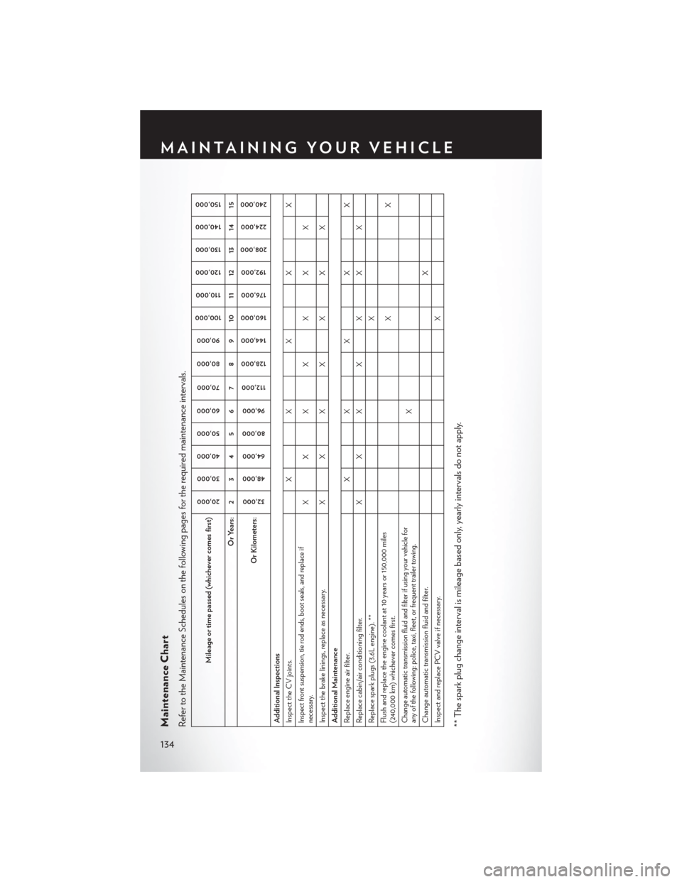
Maintenance ChartRefer to the Maintenance Schedules on the following pages for the required maintenance intervals.
Mileage or time passed (whichever comes first)
20,000
30,000
40,000
50,000
60,000
70,000
80,000
90,000
100,000
110,000
120,000
130,000
140,000
150,000
Or Years: 2 3 4 5 6 7 8 9 10 11 12 13 14 15
Or Kilometers:
32,000
48,000
64,000
80,000
96,000
112,000
128,000
144,000
160,000
176,000
192,000
208,000
224,000
240,000
Additional InspectionsInspect the CV joints. X X X X XInspect front suspension, tie rod ends, boot seals, and replace ifnecessary.
XXX X XXX
Inspect the brake linings, replace as necessary.
X
X
X
X
X
X
X
Additional MaintenanceReplace engine air filter.
X
X
X
X
X
Replace cabin/air conditioning filter.
X
X
X
X
X
X
X
Replace spark plugs (3.6L engine). **
X
Flush and replace the engine coolant at 10 years or 150,000 miles(240,000 km) whichever comes first.
XX
Change automatic transmission fluid and filter if using your vehicle forany of the following: police, taxi, fleet, or frequent trailer towing.
X
Change automatic transmission fluid and filter.
X
Inspect and replace PCV valve if necessary.
X
** The spark plug change interval is mileage based only, yearly intervals do not apply.
MAINTAINING YOUR VEHICLE
134
Page 141 of 164
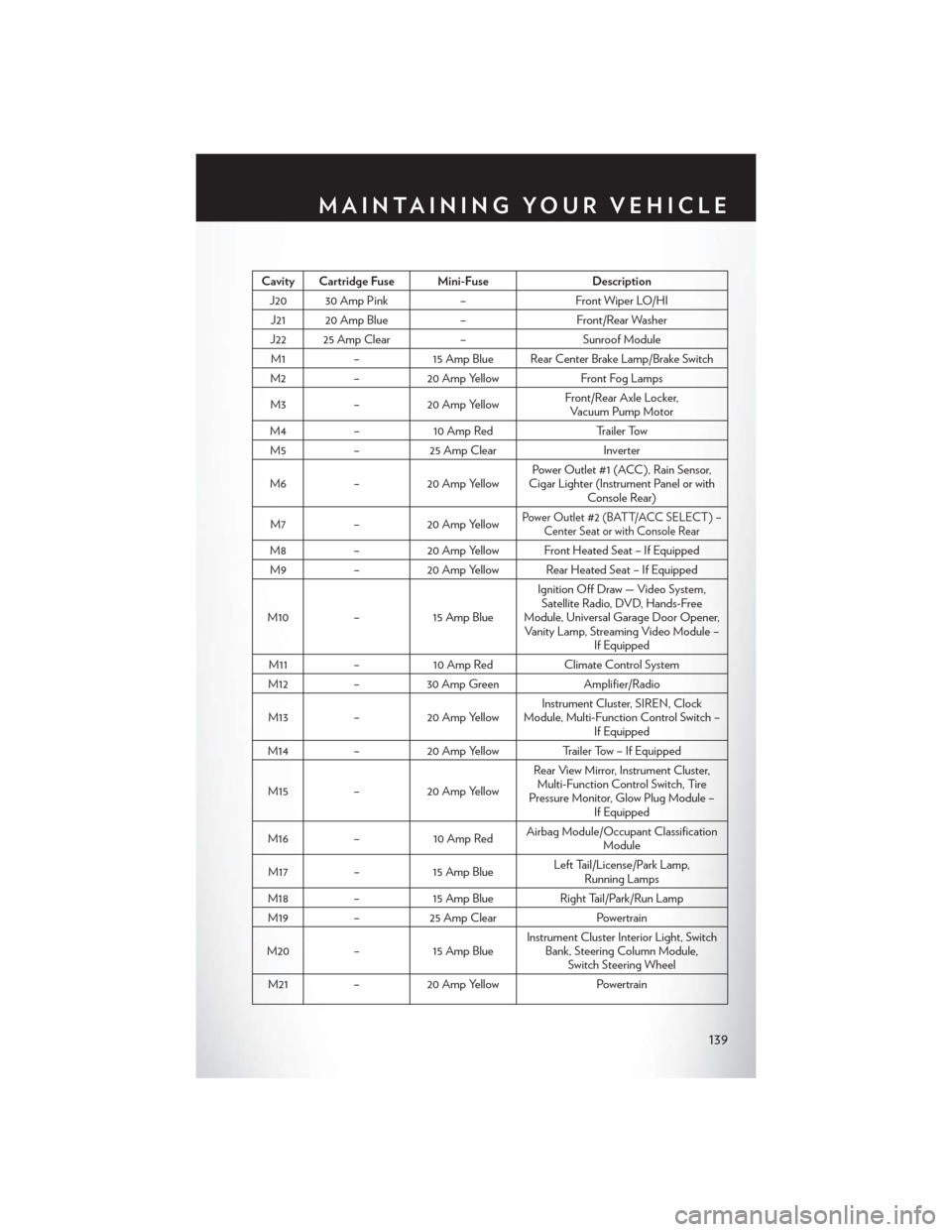
Cavity Cartridge Fuse Mini-FuseDescription
J20 30 Amp Pink–Front Wiper LO/HI
J21 20 Amp Blue–Front/Rear Washer
J22 25 Amp Clear–Sunroof Module
M1–15 Amp Blue Rear Center Brake Lamp/Brake Switch
M2–20 Amp YellowFront Fog Lamps
M3–20 Amp YellowFront/Rear Axle Locker,Vacuum Pump Motor
M4–10 Amp RedTr a i l e r To w
M5–25 Amp ClearInverter
M6–20 Amp YellowPower Outlet #1 (ACC ), Rain Sensor,Cigar Lighter (Instrument Panel or withConsole Rear)
M7–20 Amp YellowPower Outlet #2 (BATT/ACC SELECT ) –Center Seat or with Console Rear
M8–20 Amp Yellow Front Heated Seat – If Equipped
M9–20 Amp Yellow Rear Heated Seat – If Equipped
M10–15 Amp Blue
Ignition Off Draw — Video System,Satellite Radio, DVD, Hands-FreeModule, Universal Garage Door Opener,Vanity Lamp, Streaming Video Module –If Equipped
M11–10 Amp RedClimate Control System
M12–30 Amp GreenAmplifier/Radio
M13–20 Amp YellowInstrument Cluster, SIREN, ClockModule, Multi-Function Control Switch –If Equipped
M14–20 Amp YellowTrailer Tow – If Equipped
M15–20 Amp Yellow
Rear View Mirror, Instrument Cluster,Multi-Function Control Switch, TirePressure Monitor, Glow Plug Module –If Equipped
M16–10 Amp RedAirbag Module/Occupant ClassificationModule
M17–15 Amp BlueLeft Tail/License/Park Lamp,Running Lamps
M18–15 Amp BlueRight Tail/Park/Run Lamp
M19–25 Amp ClearPowertrain
M20–15 Amp BlueInstrument Cluster Interior Light, SwitchBank, Steering Column Module,Switch Steering Wheel
M21–20 Amp YellowPowertrain
MAINTAINING YOUR VEHICLE
139
Page 150 of 164
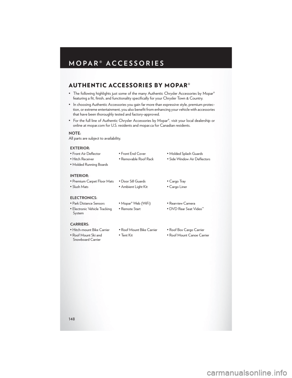
AUTHENTIC ACCESSORIES BY MOPAR®
•ThefollowinghighlightsjustsomeofthemanyAuthenticChryslerAccessoriesbyMopar®
featuring a fit, finish, and functionality specifically for your Chrysler Town & Country.
•InchoosingAuthenticAccessoriesyougainfarmorethanexpressivestyle,premiumprotec-
tion, or extreme entertainment, you also benefit from enhancing your vehicle with accessories
that have been thoroughly tested and factory-approved.
•ForthefulllineofAuthenticChryslerAccessoriesbyMopar®,visityourlocaldealershipor
online at mopar.com for U.S. residents and mopar.ca for Canadian residents.
NOTE:
All parts are subject to availability.
EXTERIOR:
•FrontAirDeflector •FrontEndCover•MoldedSplashGuards
•HitchReceiver•RemovableRoofRack •SideWindowAirDeflectors
•MoldedRunningBoards
INTERIOR:
• Premium Carpet Floor Mats • Door Sill Guards• Cargo Tray
• Slush Mats• Ambient Light Kit• Cargo Liner
ELECTRONICS:
•ParkDistanceSensors •Mopar®Web(WiFi) •RearviewCamera
• Electronic Vehicle TrackingSystem• Remote Start• DVD Rear Seat Video™
CARRIERS:
• Hitch-mount Bike Carrier • Roof Mount Bike Carrier • Roof Box Cargo Carrier
• Roof Mount Ski andSnowboard Carrier• Tent Kit• Roof Mount Canoe Carrier
MOPAR® ACCESSORIES
148
Page 151 of 164
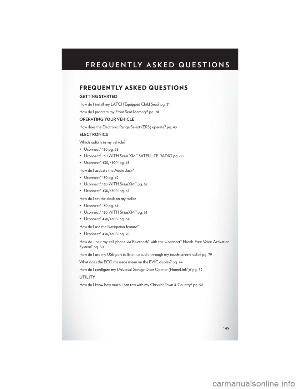
FREQUENTLY ASKED QUESTIONS
GETTING STARTED
How do I install my LATCH Equipped Child Seat? pg. 21
How do I program my Front Seat Memory? pg. 28
OPERATING YOUR VEHICLE
How does the Electronic Range Select (ERS) operate? pg. 43
ELECTRONICS
Which radio is in my vehicle?
• Uconnect® 130 pg. 58
• Uconnect® 130 WITH Sirius XM™ SATELLITE RADIO pg. 60
• Uconnect® 430/430N pg. 63
How do I activate the Audio Jack?
• Uconnect® 130 pg. 62
• Uconnect® 130 WITH SiriusXM™ pg. 62
• Uconnect® 430/430N pg. 67
How do I set the clock on my radio?
• Uconnect® 130 pg. 61
• Uconnect® 130 WITH SiriusXM™ pg. 61
• Uconnect® 430/430N pg. 64
How do I use the Navigation feature?
• Uconnect® 430/430N pg. 70
How do I pair my cell phone via Bluetooth® with the Uconnect® Hands-Free Voice Activation
System? pg. 80
How do I use my USB port to listen to audio through my touch-screen radio? pg. 79
What does the ECO message mean on the EVIC display? pg. 44
How do I configure my Universal Garage Door Opener (HomeLink®)? pg. 89
UTILITY
How do I know how much I can tow with my Chrysler Town & Country? pg. 96
FREQUENTLY ASKED QUESTIONS
149