lock CHRYSLER TOWN AND COUNTRY 2015 5.G Service Manual
[x] Cancel search | Manufacturer: CHRYSLER, Model Year: 2015, Model line: TOWN AND COUNTRY, Model: CHRYSLER TOWN AND COUNTRY 2015 5.GPages: 164, PDF Size: 22.47 MB
Page 121 of 164

4. Using the winch T-handle, rotate the drive nut to the right until the compact spare tire/cover
assembly is drawn into place against the underside of the vehicle.
5. Continue to rotate the nut to the right until you hear the winch mechanism click three times.
It cannot be overtightened. Check under the vehicle to ensure the compact spare tire/cover
assembly is positioned correctly against the underside of the vehicle.
Road Tire Installation
Ve h i c l e s E q u i p p e d W i t h W h e e l C o v e r s
1. Mount the road tire on the axle.
2. To ease the installation process for steel wheels with wheel covers, install two lug nuts on the
mounting studs which are on each side of the valve stem. Install the lug nuts with the cone
shaped end of the nut toward the wheel. Lightly tighten the lug nuts.
3. Align the valve notch in the wheel cover with
the valve stem on the wheel. Install the cover
by hand, snapping the cover over the two
lug nuts. Do not use a hammer or excessive
force to install the cover.
4. Install the remaining lug nuts with the cone
shaped end of the nut toward the wheel.
Lightly tighten the lug nuts.
5. Lower the vehicle to the ground by turning
the jack handle counterclockwise.
6. Finish tightening the lug nuts. Push down on
the wrench while at the end of the handle for
increased leverage. Tighten the lug nuts in a
star pattern until each nut has been tight-
ened twice. The correct tightness of each
lug nut is 100 ft/lbs (135 N·m). If in doubt
about the correct tightness, have them
checked with a torque wrench by your au-
thorized dealer or service station.
7. After 25 miles (40 km) check the lug nut torque with a torque wrench to ensure that all lug nuts
are properly seated against the wheel.
Wheel Cover Installation
1—ValveStem2—ValveNotch3—WheelLugNut4—WheelCover5—MountingStud
WHAT TO DO IN EMERGENCIES
119
Page 122 of 164
Ve h i c l e s W i t h o u t W h e e l C o v e r s
1. Mount the road tire on the axle.
2. Install the remaining lug nuts with the cone shaped end of the nut toward the wheel. Lightly
tighten the lug nuts.
3. Lower the vehicle to the ground by turning the jack handle counterclockwise.
4. Finish tightening the lug nuts. Push down on the wrench while at the end of the handle for
increased leverage. Tighten the lug nuts in a star pattern until each nut has been tightened
twice. The correct tightness of each lug nut is 100 ft/lbs (135 N·m). If in doubt about the
correct tightness, have them checked with a torque wrench by your authorized dealer or
service station.
5. After 25 miles (40 km) check the lug nut torque with a torque wrench to ensure that all lug nuts
are properly seated against the wheel.
CAUTION!
• The winch mechanism is designed for use with the winch T-handle only. Use of air wrench
or other power tools is not recommended and can damage the winch.
•Donotattempttoraisethevehiclebyjackingonlocationsotherthanthoseindicatedin
the Jacking Instructions for this vehicle.
•Besuretomountthesparetirewiththevalvestemfacingoutward.Thevehiclecouldbe
damaged if the spare tire is mounted incorrectly.
•Thecompactsparetire/coverassemblymustbeusedwhenthecompactsparetireis
stored. Failure to use this cover could drastically reduce the life of the compact spare tire.
•Thewinchmechanismisdesignedspecificallytostowacompactsparetireonly.Donot
attempt to use the winch to stow the full size flat tire, or any other full-size tire. Vehicle
damage may result.
WHAT TO DO IN EMERGENCIES
120
Page 123 of 164
WARNING!
•Donotattempttochangeatireonthesideofthevehicleclosetomovingtraffic.Pullfar
enough off the road to avoid the danger of being hit when operating the jack or changing
the wheel.
•Beingunderajacked-upvehicleisdangerous.Thevehiclecouldslipoffthejackandfallon
you. You could be crushed. Never put any part of your body under a vehicle that is on a
jack. If you need to get under a raised vehicle, take it to a service center where it can be
raised on a lift.
•Neverstartorruntheenginewhilethevehicleisonajack.
• The jack is designed to be used as a tool for changing tires only. The jack should not be
used to lift the vehicle for service purposes. The vehicle should be jacked on a firm level
surface only. Avoid ice or slippery areas.
•Carefullyfollowthesetirechangingwarningstohelppreventpersonalinjuryordamageto
your vehicle:
•Alwaysparkonafirm,levelsurfaceasfarfromtheedgeoftheroadwayaspossiblebefore
raising the vehicle.
• Turn on the Hazard Warning flasher.
• Block the wheel diagonally opposite the wheel to be raised.
•SettheparkingbrakefirmlyandsetanautomatictransmissioninPARK;amanual
transmission in REVERSE.
•Donotletanyonesitinthevehiclewhenitisonajack.
•Donotgetunderthevehiclewhenitisonajack.
•Onlyusethejackinthepositionsindicatedandforliftingthisvehicleduringatirechange.
•Ifworkingonorneararoadway,beextremelycarefulofmotortraffic.
•Toassurethatsparetires,flatorinflated,aresecurelystowed,sparesmustbestowedwith
the valve stem facing the ground.
•Raisingthevehiclehigherthannecessarycanmakethevehiclelessstable.Itcouldslipoff
the jack and hurt someone near it. Raise the vehicle only enough to remove the tire.
•Toavoidtheriskofforcingthevehicleoffthejack,donottightenthewheelnutsfullyuntil
the vehicle has been lowered. Failure to follow this warning may result in personal injury.
•Aloosetireorjackthrownforwardinacollisionorhardstopcouldendangertheoccupants
of the vehicle. Always stow the jack parts andthe spare tire in the places provided. Have
the deflated (flat) tire repaired or replaced immediately.
•Verifythatbothretainertabsofthewheelspacerhavebeenproperlyextendedthrough
the center of the wheel and spare tire/cover assembly. Failure to properly engage both
retainer tabs could result in loss of the spare tire and cover assembly, which will cause
vehicle damage and may cause loss of vehicle control.
WHAT TO DO IN EMERGENCIES
121
Page 124 of 164
JUMP-STARTING
If your vehicle has a discharged battery it can be jump-started using a set of jumper cables and a
battery in another vehicle or by using a portable battery booster pack.
Jump-starting can be dangerous if done improperly so please follow the procedures in this
section carefully.
NOTE:
When using a portable battery booster pack
follow the manufacturer’s operating instruc-
tions and precautions.
Preparations For Jump-Start
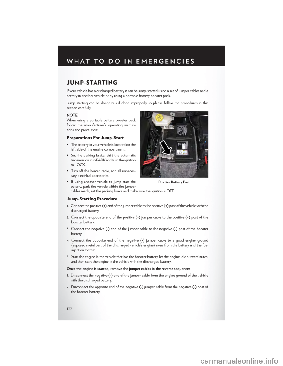
•Thebatteryinyourvehicleislocatedonthe
left side of the engine compartment.
•Settheparkingbrake,shifttheautomatic
transmission into PARK and turn the ignition
to LOCK.
• Turn off the heater, radio, and all unneces-
sary electrical accessories.
•Ifusinganothervehicletojump-startthe
battery, park the vehicle within the jumper
cables reach, set the parking brake and make sure the ignition is OFF.
Jump-Starting Procedure
1. Connect the positive(+)end of the jumper cable to the positive(+)post of the vehicle with the
discharged battery.
2. Connect the opposite end of the positive(+)jumper cable to the positive(+)post of the
booster battery.
3. Connect the negative(-)end of the jumper cable to the negative(-)post of the booster
battery.
4. Connect the opposite end of the negative(-)jumper cable to a good engine ground
(exposed metal part of the discharged vehicle’s engine) away from the battery and the fuel
injection system.
5. Start the engine in the vehicle that has the booster battery, let the engine idle a few minutes,
and then start the engine in the vehicle with the discharged battery.
Once the engine is started, remove the jumper cables in the reverse sequence:
1. Disconnect the negative(-)end of the jumper cable from the engine ground of the vehicle
with the discharged battery.
2. Disconnect the opposite end of the negative(-)jumper cable from the negative(-)post of
the booster battery.
Positive Battery Post
WHAT TO DO IN EMERGENCIES
122
Page 129 of 164

OPENING THE HOOD
1. Pull the hood release lever located on the
instrument panel, below the steering col-
umn.
2. Raise the hood and locate the safety catch
lever, in the middle of the hood opening.
3. Move the safety latch while lifting the hood
at the same time.
4. Insert the support rod into the slot on the
hood.
5. To close the hood, remove the support rod
and place it in the retaining clip, then lower
the hood slowly.
WARNING!
Be sure the hood is fully latched before driving your vehicle. If the hood is not fully latched, it
could open when the vehicle is in motion and block your vision. Failure to follow this warning
could result in serious injury or death.
Hood Release Lever
MAINTAINING YOUR VEHICLE
127
Page 140 of 164
To t a l l y I n t e g r a t e d P o w e r M o d u l e ( F u s e s )
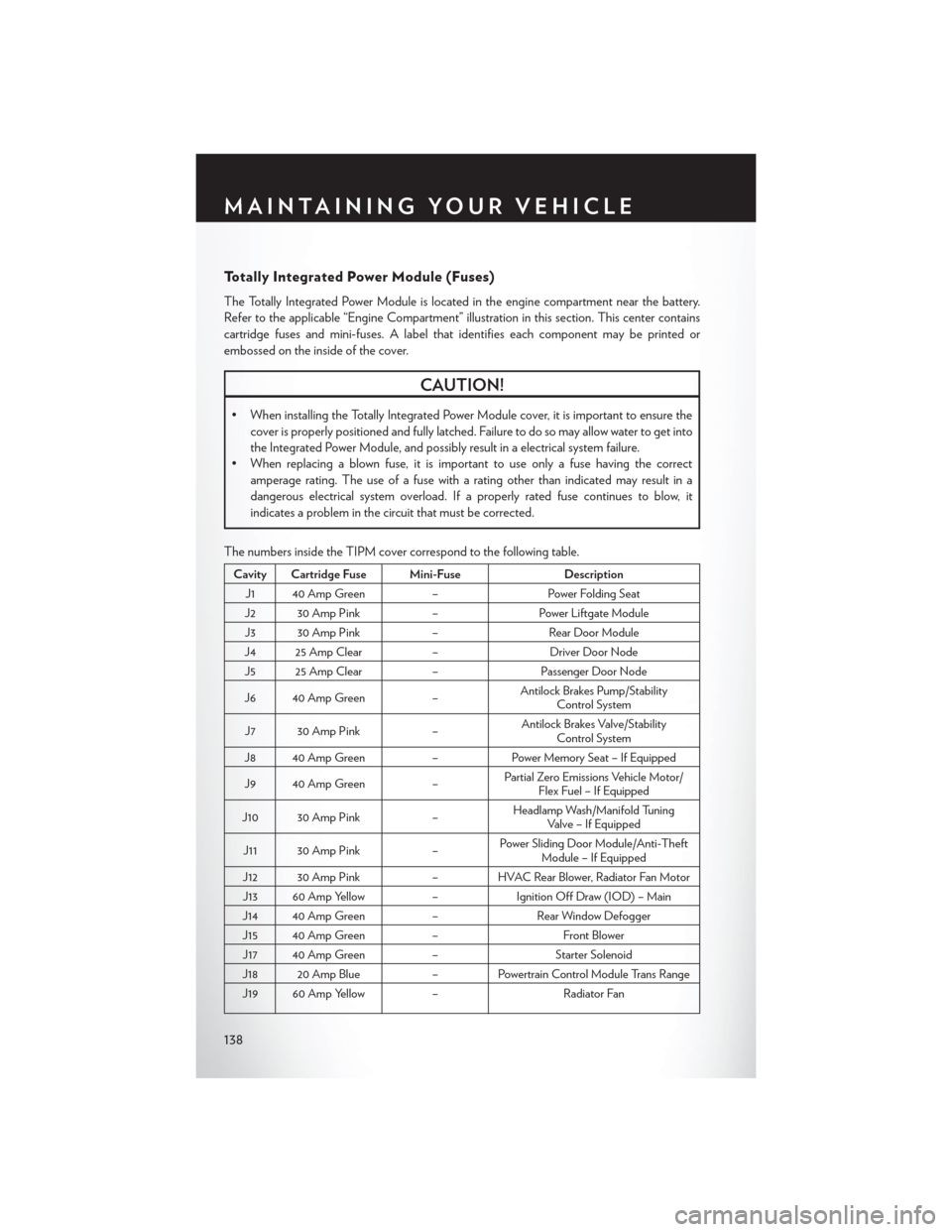
The Totally Integrated Power Module is located in the engine compartment near the battery.
Refer to the applicable “Engine Compartment” illustration in this section. This center contains
cartridge fuses and mini-fuses. A label that identifies each component may be printed or
embossed on the inside of the cover.
CAUTION!
•WheninstallingtheTotallyIntegratedPowerModulecover,itisimportanttoensurethe
cover is properly positioned and fully latched. Failure to do so may allow water to get into
the Integrated Power Module, and possibly result in a electrical system failure.
• When replacing a blown fuse, it is important to use only a fuse having the correct
amperage rating. The use of a fuse with a rating other than indicated may result in a
dangerous electrical system overload. If a properly rated fuse continues to blow, it
indicates a problem in the circuit that must be corrected.
The numbers inside the TIPM cover correspond to the following table.
Cavity Cartridge Fuse Mini-FuseDescription
J1 40 Amp Green–Power Folding Seat
J2 30 Amp Pink–Power Liftgate Module
J3 30 Amp Pink–Rear Door Module
J4 25 Amp Clear–Driver Door Node
J5 25 Amp Clear–Passenger Door Node
J6 40 Amp Green–Antilock Brakes Pump/StabilityControl System
J7 30 Amp Pink–Antilock Brakes Valve/StabilityControl System
J8 40 Amp Green–Power Memory Seat – If Equipped
J9 40 Amp Green–Partial Zero Emissions Vehicle Motor/Flex Fuel – If Equipped
J10 30 Amp Pink–Headlamp Wash/Manifold TuningVa l v e – I f E q u i p p e d
J11 30 Amp Pink–Power Sliding Door Module/Anti-TheftModule – If Equipped
J12 30 Amp Pink– HVAC Rear Blower, Radiator Fan Motor
J13 60 Amp Yellow–Ignition Off Draw (IOD) – Main
J14 40 Amp Green–Rear Window Defogger
J15 40 Amp Green–Front Blower
J17 40 Amp Green–Starter Solenoid
J18 20 Amp Blue–PowertrainControlModuleTransRange
J19 60 Amp Yellow–Radiator Fan
MAINTAINING YOUR VEHICLE
138
Page 141 of 164
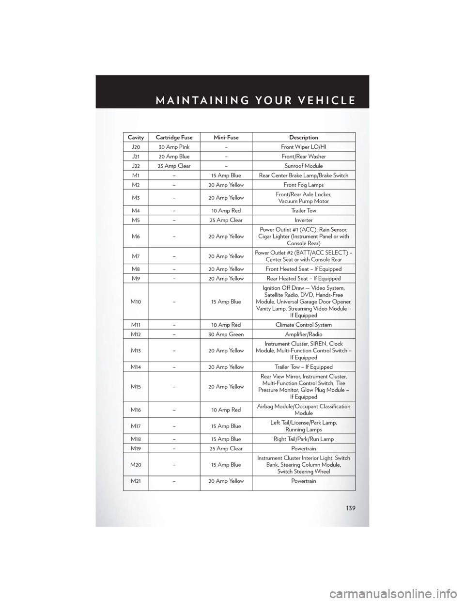
Cavity Cartridge Fuse Mini-FuseDescription
J20 30 Amp Pink–Front Wiper LO/HI
J21 20 Amp Blue–Front/Rear Washer
J22 25 Amp Clear–Sunroof Module
M1–15 Amp Blue Rear Center Brake Lamp/Brake Switch
M2–20 Amp YellowFront Fog Lamps
M3–20 Amp YellowFront/Rear Axle Locker,Vacuum Pump Motor
M4–10 Amp RedTr a i l e r To w
M5–25 Amp ClearInverter
M6–20 Amp YellowPower Outlet #1 (ACC ), Rain Sensor,Cigar Lighter (Instrument Panel or withConsole Rear)
M7–20 Amp YellowPower Outlet #2 (BATT/ACC SELECT ) –Center Seat or with Console Rear
M8–20 Amp Yellow Front Heated Seat – If Equipped
M9–20 Amp Yellow Rear Heated Seat – If Equipped
M10–15 Amp Blue
Ignition Off Draw — Video System,Satellite Radio, DVD, Hands-FreeModule, Universal Garage Door Opener,Vanity Lamp, Streaming Video Module –If Equipped
M11–10 Amp RedClimate Control System
M12–30 Amp GreenAmplifier/Radio
M13–20 Amp YellowInstrument Cluster, SIREN, ClockModule, Multi-Function Control Switch –If Equipped
M14–20 Amp YellowTrailer Tow – If Equipped
M15–20 Amp Yellow
Rear View Mirror, Instrument Cluster,Multi-Function Control Switch, TirePressure Monitor, Glow Plug Module –If Equipped
M16–10 Amp RedAirbag Module/Occupant ClassificationModule
M17–15 Amp BlueLeft Tail/License/Park Lamp,Running Lamps
M18–15 Amp BlueRight Tail/Park/Run Lamp
M19–25 Amp ClearPowertrain
M20–15 Amp BlueInstrument Cluster Interior Light, SwitchBank, Steering Column Module,Switch Steering Wheel
M21–20 Amp YellowPowertrain
MAINTAINING YOUR VEHICLE
139
Page 142 of 164
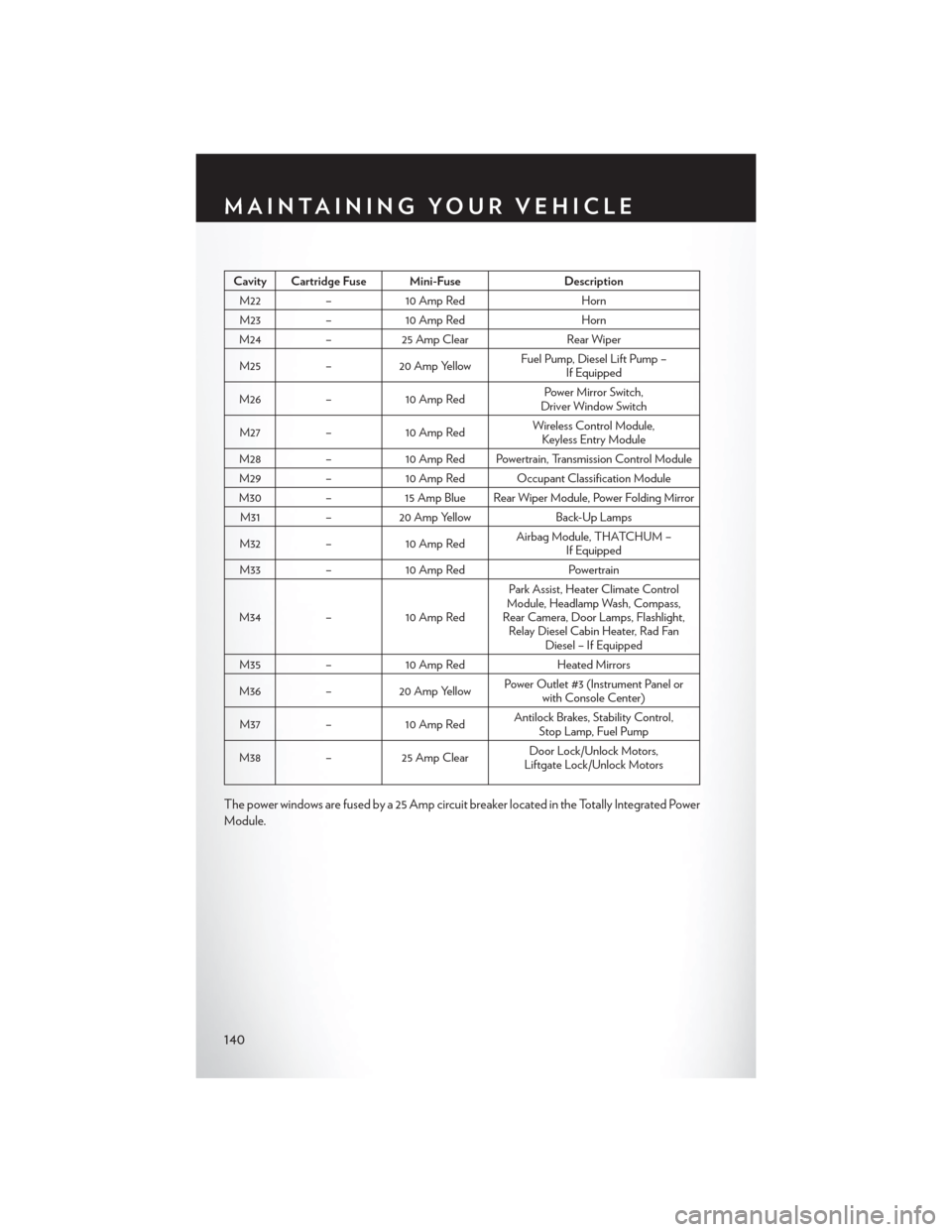
Cavity Cartridge Fuse Mini-FuseDescription
M22–10 Amp RedHorn
M23–10 Amp RedHorn
M24–25 Amp ClearRear Wiper
M25–20 Amp YellowFuel Pump, Diesel Lift Pump –If Equipped
M26–10 Amp RedPower Mirror Switch,Driver Window Switch
M27–10 Amp RedWireless Control Module,Keyless Entry Module
M28–10 Amp Red Powertrain, Transmission Control Module
M29–10 Amp Red Occupant Classification Module
M30–15 Amp Blue Rear Wiper Module, Power Folding Mirror
M31–20 Amp YellowBack-Up Lamps
M32–10 Amp RedAirbag Module, THATCHUM –If Equipped
M33–10 Amp RedPowertrain
M34–10 Amp Red
Park Assist, Heater Climate ControlModule, Headlamp Wash, Compass,Rear Camera, Door Lamps, Flashlight,Relay Diesel Cabin Heater, Rad FanDiesel – If Equipped
M35–10 Amp RedHeated Mirrors
M36–20 Amp YellowPower Outlet #3 (Instrument Panel orwith Console Center)
M37–10 Amp RedAntilock Brakes, Stability Control,Stop Lamp, Fuel Pump
M38–25 Amp ClearDoor Lock/Unlock Motors,Liftgate Lock/Unlock Motors
The power windows are fused by a 25 Amp circuit breaker located in the Totally Integrated Power
Module.
MAINTAINING YOUR VEHICLE
140
Page 151 of 164
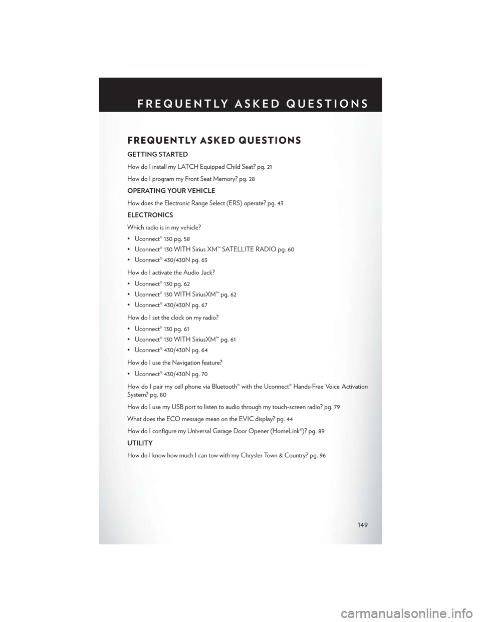
FREQUENTLY ASKED QUESTIONS
GETTING STARTED
How do I install my LATCH Equipped Child Seat? pg. 21
How do I program my Front Seat Memory? pg. 28
OPERATING YOUR VEHICLE
How does the Electronic Range Select (ERS) operate? pg. 43
ELECTRONICS
Which radio is in my vehicle?
• Uconnect® 130 pg. 58
• Uconnect® 130 WITH Sirius XM™ SATELLITE RADIO pg. 60
• Uconnect® 430/430N pg. 63
How do I activate the Audio Jack?
• Uconnect® 130 pg. 62
• Uconnect® 130 WITH SiriusXM™ pg. 62
• Uconnect® 430/430N pg. 67
How do I set the clock on my radio?
• Uconnect® 130 pg. 61
• Uconnect® 130 WITH SiriusXM™ pg. 61
• Uconnect® 430/430N pg. 64
How do I use the Navigation feature?
• Uconnect® 430/430N pg. 70
How do I pair my cell phone via Bluetooth® with the Uconnect® Hands-Free Voice Activation
System? pg. 80
How do I use my USB port to listen to audio through my touch-screen radio? pg. 79
What does the ECO message mean on the EVIC display? pg. 44
How do I configure my Universal Garage Door Opener (HomeLink®)? pg. 89
UTILITY
How do I know how much I can tow with my Chrysler Town & Country? pg. 96
FREQUENTLY ASKED QUESTIONS
149
Page 152 of 164
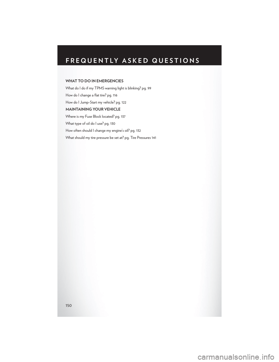
WHAT TO DO IN EMERGENCIES
What do I do if my TPMS warning light is blinking? pg. 99
How do I change a flat tire? pg. 116
How do I Jump-Start my vehicle? pg. 122
MAINTAINING YOUR VEHICLE
Where is my Fuse Block located? pg. 137
What type of oil do I use? pg. 130
How often should I change my engine’s oil? pg. 132
What should my tire pressure be set at? pg. Tire Pressures 141
FREQUENTLY ASKED QUESTIONS
150