spare wheel CHRYSLER TOWN AND COUNTRY 2015 5.G User Guide
[x] Cancel search | Manufacturer: CHRYSLER, Model Year: 2015, Model line: TOWN AND COUNTRY, Model: CHRYSLER TOWN AND COUNTRY 2015 5.GPages: 164, PDF Size: 22.47 MB
Page 3 of 164
INTRODUCTION/WELCOME
WELCOME FROM CHRYSLERGROUP LLC . . . . . . . . . . . . . . . . . . 3
CONTROLS AT A GLANCE
DRIVER COCKPIT...............6INSTRUMENT CLUSTER...........8
GETTING STARTED
KEY FOB . . . . . . . . . . . . . . . . . . . . 10REMOTE START...............12KEYLESS ENTER-N-GO™..........12VEHICLE SECURITY ALARM........16SEAT BELT SYSTEMS.............17SUPPLEMENTAL RESTRAINTSYSTEM (SRS) — AIR BAGS.........18CHILD RESTRAINTS.............21HEAD RESTRAINTS.............25FRONT SEATS . . . . . . . . . . . . . . . . 27REAR SEATS..................29HEATED SEATS . . . . . . . . . . . . . . . . 34HEATED STEERING WHEEL........35TILT/TELESCOPING STEERINGCOLUMN . . . . . . . . . . . . . . . . . . . 35ADJUSTABLE PEDALS............36
OPERATING YOUR VEHICLE
ENGINE BREAK-INRECOMMENDATIONS............37TURN SIGNAL/WIPER/WASHER/HIGHBEAM LEVER.................38HEADLIGHT SWITCH AND HALOLIGHT SWITCH . . . . . . . . . . . . . . . . 40ELECTRONIC SPEED CONTROL......41ELECTRONIC RANGE SELECTION (ERS) . . 43FUEL ECONOMY (ECON) MODE.....44MANUAL CLIMATE CONTROLS......45THREE ZONE MANUAL CLIMATECONTROLS..................46THREE ZONE AUTOMATICTEMPERATURE CONTROLS (ATC)....48PA R K S E N S E ® R E A R PA R K A S S I S T.....51PA R K V I E W ® R E A R B AC K- U P C A M E R A . . 5 1BLIND SPOT MONITORING WITHREAR CROSS PATH . .............51POWER SLIDING SIDE DOORS .......52POWER LIFTGATE . . . . . . . . . . . . . . 52POWER SUNROOF.............53WIND BUFFETING..............55
ELECTRONICS
YO U R V E H I C L E ' S S O U N D SYS T E M....56Uconnect® 130..................58Uconnect® 130 WITH SiriusXM SATELLITERADIO.....................60Uconnect® 430/430N..............63
SiriusXM SATELLITE RADIO/TRAVELLINK . . . . . . . . . . . . . . . . . . . . . . . 73STEERING WHEEL AUDIO CONTROLS..78SETTING THE ANALOG CLOCK . . . . . 78iPod®/USB/MP3 CONTROL.........79Uconnect® Phone ................80Uconnect® VOICE COMMAND . . . . . . . 82Bluetooth® STREAMING AUDIO . . . . . . 85VIDEO ENTERTAINMENTSYSTEM (VES™)................85ELECTRONIC VEHICLE INFORMATIONCENTER (EVIC) ................87PROGRAMMABLE FEATURES.......88UNIVERSAL GARAGE DOOR OPENER(HomeLink®)..................89POWER INVERTER..............92POWER OUTLETS..............93
UTILITY
IN-FLOOR STORAGE — STOW'N GO® . . 95ROOF LUGGAGE RACK..........95TRAILER TOWING WEIGHTS(MAXIMUM TRAILER WEIGHTRATINGS) . . . . . . . . . . . . . . . . . . . 96RECREATIONAL TOWING(BEHIND MOTORHOME, ETC.)......97
WHAT TO DO IN EMERGENCIES
ROADSIDE ASSISTANCE..........98INSTRUMENT CLUSTER WARNINGLIGHTS . . . . . . . . . . . . . . . . . . . . . 98INSTRUMENT CLUSTER INDICATORLIGHTS . . . . . . . . . . . . . . . . . . . . 102IF YOUR ENGINE OVERHEATS . . . . . . 104TIRE SERVICE KIT . . . . . . . . . . . . . . 104JACKING AND TIRE CHANGING . . . . . 110JUMP-STARTING..............122SHIFT LEVER OVERRIDE..........124TOWING A DISABLED VEHICLE.....124FREEING A STUCK VEHICLE . ......125EVENT DATA RECORDER (EDR).....126
MAINTAINING YOUR VEHICLE
OPENING THE HOOD...........127ENGINE COMPARTMENT.........128FLUID CAPACITIES . . . . . . . . . . . . . 130FLUIDS, LUBRICANTS ANDGENUINE PARTS . .............130MAINTENANCE PROCEDURES . . . . . . 132MAINTENANCE SCHEDULE . . .....132MAINTENANCE RECORD.........136FUSES.....................137TIRE PRESSURES...............141SPARE TIRES — IF EQUIPPED.......142ADDING FUEL................143WHEEL AND WHEEL TRIM CARE . . . . . 144REPLACEMENT BULBS...........145
TA B L E O F CO N T E N TS
Page 101 of 164
If the light remains lit with the engine running, your vehicle will usually be drivable; however, see
an authorized dealer immediately. If the light is flashing when the engine is running, immediate
service is required and you may experience reduced performance, an elevated/rough idle or
engine stall and your vehicle may require towing.
-TirePressureMonitoringSystem(TPMS)Light
Each tire, including the spare (if provided), should be checked monthly when cold and inflated to
the inflation pressure recommended by the vehicle manufacturer on the vehicle placard or tire
inflation pressure label. (If your vehicle has tires of a different size than the size indicated on the
vehicle placard or tire inflation pressure label, you should determine the proper tire inflation
pressure for those tires.)
As an added safety feature, your vehicle has been equipped with a tire pressure monitoring
system (TPMS) that illuminates a low tire pressure telltale when one or more of your tires is
significantly under-inflated. Accordingly, when the low tire pressure telltale illuminates, you
should stop and check your tires as soon as possible, and inflate them to the proper pressure.
Driving on a significantly under-inflated tire causes the tire to overheat and can lead to tire failure.
Under-inflation also reduces fuel efficiency and tire tread life, and may affect the vehicle’s
handling and stopping ability.
IF THE LIGHT STARTS FLASHING INDICATING A LOW TIRE PRESSURE, ADJUST
THE AIR PRESSURE IN THE LOW TIRE TO THE AIR PRESSURE SHOWN ON THE
VEHICLE PLACARD OR TIRE INFLATION PRESSURE LABEL LOCATED ON THE
DRIVER'S DOOR.
NOTE:
AFTER INFLATION, THE VEHICLE MAY NEED TO BE DRIVEN FOR 20 MINUTES
BEFORE THE FLASHING LIGHT WILL TURN OFF.
Please note that the TPMS is not a substitute for proper tire maintenance, and it is the driver’s
responsibility to maintain correct tire pressure, even if under-inflation has not reached the level to
trigger illumination of the TPMS low tire pressure telltale.
Yo u r v e h i c l e h a s a l s o b e e n e q u i p p e d w i t h a T P M S m a l f u n c t i o n i n d i c a t o r t o i n d i c a t e w h e n t h e
system is not operating properly. The TPMS malfunction indicator is combined with the low tire
pressure telltale.
When the system detects a malfunction, the telltale will flash for approximately one minute and
then remain continuously illuminated. This sequence will continue upon subsequent vehicle
start-ups as long as the malfunction exists. When the malfunction indicator is illuminated, the
system may not be able to detect or signal low tire pressure as intended. TPMS malfunctions may
occur for a variety of reasons, including the installation of replacement or alternate tires or wheels
on the vehicle that prevent the TPMS from functioning properly. Always check the TPMS
malfunction telltale after replacing one or more tires or wheels on your vehicle to ensure that the
replacement or alternate tires and wheels allow the TPMS to continue to function properly.
WHAT TO DO IN EMERGENCIES
99
Page 117 of 164
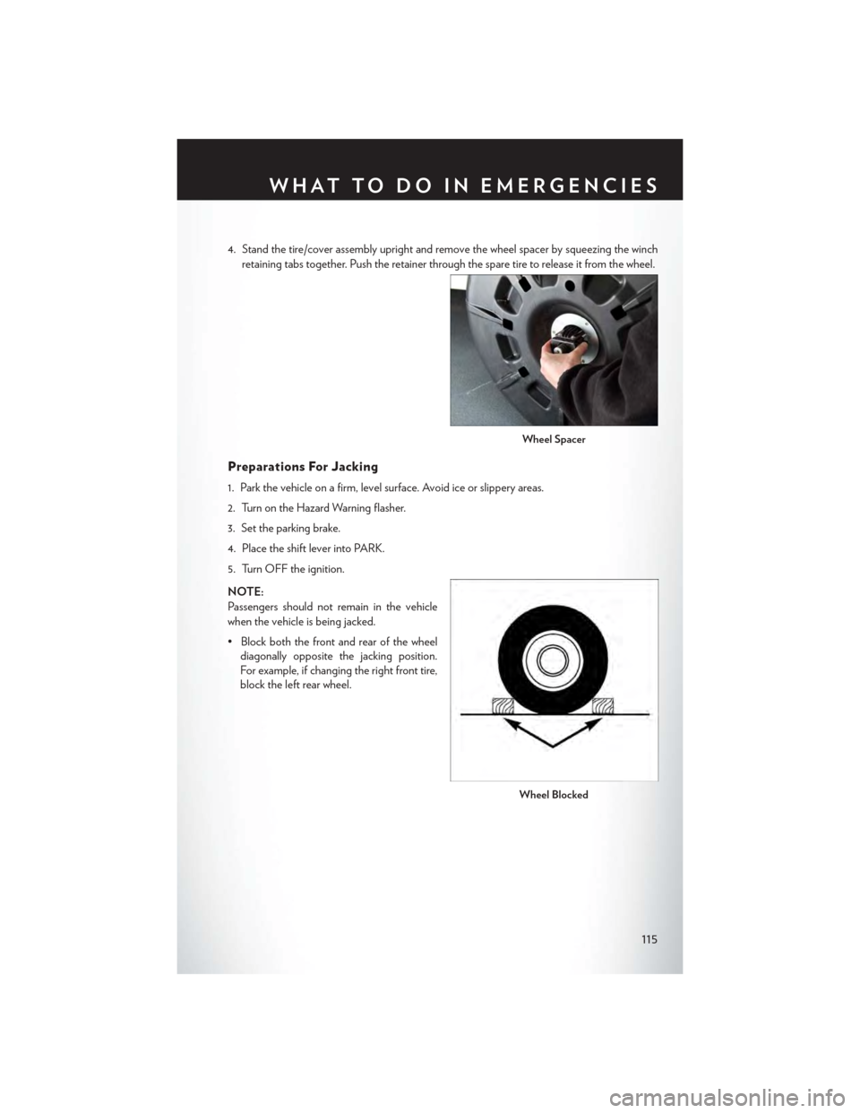
4. Stand the tire/cover assembly upright and remove the wheel spacer by squeezing the winch
retaining tabs together. Push the retainer through the spare tire to release it from the wheel.
Preparations For Jacking
1. Park the vehicle on a firm, level surface. Avoid ice or slippery areas.
2. Turn on the Hazard Warning flasher.
3. Set the parking brake.
4. Place the shift lever into PARK.
5. Turn OFF the ignition.
NOTE:
Passengers should not remain in the vehicle
when the vehicle is being jacked.
• Block both the front and rear of the wheel
diagonally opposite the jacking position.
For example, if changing the right front tire,
block the left rear wheel.
Wheel Spacer
Wheel Blocked
WHAT TO DO IN EMERGENCIES
115
Page 119 of 164

Rear jack locations are between a pair of down-facing tabs on the sill flange of the vehicle
side body.
Front jack location is on the sill flange of the vehicle body and is located 6 in (150 mm) from
door edge.
NOTE:
In some situations the jack may need to be
placed on its side in order to be pushed under
the vehicle. Return the jack to its correct orien-
tation once it is under the vehicle.
3. Place the wrench on the jack screw and turn to the right until the jack head is properly engaged
in the described location.Do not raise the vehicle until you are sure the jack is securely
engaged.
4. Raise the vehicle by turning the jack screw to the right, using the swivel wrench. Raise the
vehicle only until the tire just clears the surface and enough clearance is obtained to install the
spare tire. Minimum tire lift provides maximum stability.
5. Remove the wheel lug nuts, for vehicles with wheel covers, remove the cover from the wheel
by hand. Do not pry the wheel cover off. Then pull the wheel off the hub.
Rear Jacking Location Engaged
Front Jacking Location Engaged
WHAT TO DO IN EMERGENCIES
117
Page 120 of 164
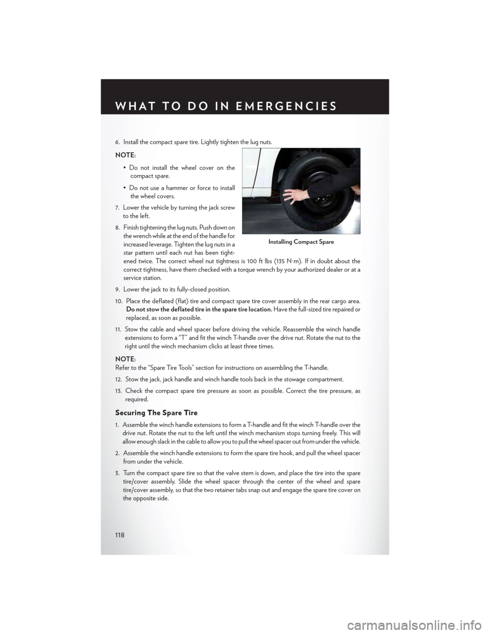
6. Install the compact spare tire. Lightly tighten the lug nuts.
NOTE:
•Donotinstallthewheelcoveronthe
compact spare.
• Do not use a hammer or force to install
the wheel covers.
7. Lower the vehicle by turning the jack screw
to the left.
8. Finish tightening the lug nuts. Push down on
the wrench while at the end of the handle for
increased leverage. Tighten the lug nuts in a
star pattern until each nut has been tight-
ened twice. The correct wheel nut tightness is 100 ft lbs (135 N·m). If in doubt about the
correct tightness, have them checked with a torque wrench by your authorized dealer or at a
service station.
9. Lower the jack to its fully-closed position.
10. Place the deflated (flat) tire and compact spare tire cover assembly in the rear cargo area.
Do not stow the deflated tire in the spare tire location.Have the full-sized tire repaired or
replaced, as soon as possible.
11. Stow the cable and wheel spacer before driving the vehicle. Reassemble the winch handle
extensions to form a “T” and fit the winch T-handle over the drive nut. Rotate the nut to the
right until the winch mechanism clicks at least three times.
NOTE:
Refer to the “Spare Tire Tools” section for instructions on assembling the T-handle.
12. Stow the jack, jack handle and winch handle tools back in the stowage compartment.
13. Check the compact spare tire pressure as soon as possible. Correct the tire pressure, as
required.
Securing The Spare Tire
1. Assemble the winch handle extensions to form a T-handle and fit the winch T-handle over the
drive nut. Rotate the nut to the left until the winch mechanism stops turning freely. This will
allow enough slack in the cable to allow you to pull the wheel spacer out from under the vehicle.
2. Assemble the winch handle extensions to form the spare tire hook, and pull the wheel spacer
from under the vehicle.
3. Turn the compact spare tire so that the valve stem is down, and place the tire into the spare
tire/cover assembly. Slide the wheel spacer through the center of the wheel and spare
tire/cover assembly, so that the two retainer tabs snap out and engage the spare tire cover on
the opposite side.
Installing Compact Spare
WHAT TO DO IN EMERGENCIES
118
Page 121 of 164

4. Using the winch T-handle, rotate the drive nut to the right until the compact spare tire/cover
assembly is drawn into place against the underside of the vehicle.
5. Continue to rotate the nut to the right until you hear the winch mechanism click three times.
It cannot be overtightened. Check under the vehicle to ensure the compact spare tire/cover
assembly is positioned correctly against the underside of the vehicle.
Road Tire Installation
Ve h i c l e s E q u i p p e d W i t h W h e e l C o v e r s
1. Mount the road tire on the axle.
2. To ease the installation process for steel wheels with wheel covers, install two lug nuts on the
mounting studs which are on each side of the valve stem. Install the lug nuts with the cone
shaped end of the nut toward the wheel. Lightly tighten the lug nuts.
3. Align the valve notch in the wheel cover with
the valve stem on the wheel. Install the cover
by hand, snapping the cover over the two
lug nuts. Do not use a hammer or excessive
force to install the cover.
4. Install the remaining lug nuts with the cone
shaped end of the nut toward the wheel.
Lightly tighten the lug nuts.
5. Lower the vehicle to the ground by turning
the jack handle counterclockwise.
6. Finish tightening the lug nuts. Push down on
the wrench while at the end of the handle for
increased leverage. Tighten the lug nuts in a
star pattern until each nut has been tight-
ened twice. The correct tightness of each
lug nut is 100 ft/lbs (135 N·m). If in doubt
about the correct tightness, have them
checked with a torque wrench by your au-
thorized dealer or service station.
7. After 25 miles (40 km) check the lug nut torque with a torque wrench to ensure that all lug nuts
are properly seated against the wheel.
Wheel Cover Installation
1—ValveStem2—ValveNotch3—WheelLugNut4—WheelCover5—MountingStud
WHAT TO DO IN EMERGENCIES
119
Page 122 of 164
Ve h i c l e s W i t h o u t W h e e l C o v e r s
1. Mount the road tire on the axle.
2. Install the remaining lug nuts with the cone shaped end of the nut toward the wheel. Lightly
tighten the lug nuts.
3. Lower the vehicle to the ground by turning the jack handle counterclockwise.
4. Finish tightening the lug nuts. Push down on the wrench while at the end of the handle for
increased leverage. Tighten the lug nuts in a star pattern until each nut has been tightened
twice. The correct tightness of each lug nut is 100 ft/lbs (135 N·m). If in doubt about the
correct tightness, have them checked with a torque wrench by your authorized dealer or
service station.
5. After 25 miles (40 km) check the lug nut torque with a torque wrench to ensure that all lug nuts
are properly seated against the wheel.
CAUTION!
• The winch mechanism is designed for use with the winch T-handle only. Use of air wrench
or other power tools is not recommended and can damage the winch.
•Donotattempttoraisethevehiclebyjackingonlocationsotherthanthoseindicatedin
the Jacking Instructions for this vehicle.
•Besuretomountthesparetirewiththevalvestemfacingoutward.Thevehiclecouldbe
damaged if the spare tire is mounted incorrectly.
•Thecompactsparetire/coverassemblymustbeusedwhenthecompactsparetireis
stored. Failure to use this cover could drastically reduce the life of the compact spare tire.
•Thewinchmechanismisdesignedspecificallytostowacompactsparetireonly.Donot
attempt to use the winch to stow the full size flat tire, or any other full-size tire. Vehicle
damage may result.
WHAT TO DO IN EMERGENCIES
120
Page 123 of 164
WARNING!
•Donotattempttochangeatireonthesideofthevehicleclosetomovingtraffic.Pullfar
enough off the road to avoid the danger of being hit when operating the jack or changing
the wheel.
•Beingunderajacked-upvehicleisdangerous.Thevehiclecouldslipoffthejackandfallon
you. You could be crushed. Never put any part of your body under a vehicle that is on a
jack. If you need to get under a raised vehicle, take it to a service center where it can be
raised on a lift.
•Neverstartorruntheenginewhilethevehicleisonajack.
• The jack is designed to be used as a tool for changing tires only. The jack should not be
used to lift the vehicle for service purposes. The vehicle should be jacked on a firm level
surface only. Avoid ice or slippery areas.
•Carefullyfollowthesetirechangingwarningstohelppreventpersonalinjuryordamageto
your vehicle:
•Alwaysparkonafirm,levelsurfaceasfarfromtheedgeoftheroadwayaspossiblebefore
raising the vehicle.
• Turn on the Hazard Warning flasher.
• Block the wheel diagonally opposite the wheel to be raised.
•SettheparkingbrakefirmlyandsetanautomatictransmissioninPARK;amanual
transmission in REVERSE.
•Donotletanyonesitinthevehiclewhenitisonajack.
•Donotgetunderthevehiclewhenitisonajack.
•Onlyusethejackinthepositionsindicatedandforliftingthisvehicleduringatirechange.
•Ifworkingonorneararoadway,beextremelycarefulofmotortraffic.
•Toassurethatsparetires,flatorinflated,aresecurelystowed,sparesmustbestowedwith
the valve stem facing the ground.
•Raisingthevehiclehigherthannecessarycanmakethevehiclelessstable.Itcouldslipoff
the jack and hurt someone near it. Raise the vehicle only enough to remove the tire.
•Toavoidtheriskofforcingthevehicleoffthejack,donottightenthewheelnutsfullyuntil
the vehicle has been lowered. Failure to follow this warning may result in personal injury.
•Aloosetireorjackthrownforwardinacollisionorhardstopcouldendangertheoccupants
of the vehicle. Always stow the jack parts andthe spare tire in the places provided. Have
the deflated (flat) tire repaired or replaced immediately.
•Verifythatbothretainertabsofthewheelspacerhavebeenproperlyextendedthrough
the center of the wheel and spare tire/cover assembly. Failure to properly engage both
retainer tabs could result in loss of the spare tire and cover assembly, which will cause
vehicle damage and may cause loss of vehicle control.
WHAT TO DO IN EMERGENCIES
121
Page 144 of 164

SPARE TIRES — IF EQUIPPED
NOTE:
For vehicles equipped with Tire Service Kit instead of a spare tire, please refer to “Tire Service Kit”
in “What To Do In Emergencies” on your DVD for further information.
CAUTION!
Because of the reduced ground clearance, do not take your vehicle through an automatic car
wash with a compact or limited-use temporary spare installed. Damage to the vehicle may
result.
Spare Tire Matching Original Equipped Tire And Wheel — If Equipped
Yo u r v e h i c l e m a y b e e q u i p p e d w i t h a s p a r e t i r e a n d w h e e l e q u i v a l e n t i n l o o k a n d f u n c t i o n t o t h e
original equipment tire and wheel found on the front or rear axle of your vehicle. This spare tire
may be used in the tire rotation for your vehicle. If your vehicle has this option, refer to an
authorized tire dealer for the recommended tire rotation pattern.
Compact Spare Tire — If Equipped
The compact spare is for temporary emergency use only. You can identify if your vehicle is
equipped with a compact spare by looking at the spare tire description on the Tire and Loading
Information Placard located on the driver’s side door opening or on the sidewall of the tire.
Compact spare tire descriptions begin with the letter “T” or “S” preceding the size designation.
Example: T145/80D18 103M.
T, S = Temporary Spare Tire
Since this tire has limited tread life, the original equipment tire should be repaired (or replaced)
and reinstalled on your vehicle at the first opportunity.
Do not install a wheel cover or attempt to mount a conventional tire on the compact spare wheel,
since the wheel is designed specifically for the compact spare tire. Do not install more than one
compact spare tire and wheel on the vehicle at any given time.
WARNING!
Compact spares are for temporary emergency use only. With these spares, do not drive more
than 50 mph (80 km/h). Temporary use spares have limited tread life. When the tread is worn
to the tread wear indicators, the temporary use spare tire needs to be replaced. Be sure to
follow the warnings, which apply to your spare. Failure to do so could result in spare tire failure
and loss of vehicle control.
MAINTAINING YOUR VEHICLE
142
Page 145 of 164

Full Size Spare — If Equipped
The full size spare is for temporary emergency use only. This tire may look like the originally
equipped tire on the front or rear axle of your vehicle, but it is not. This spare tire may have limited
tread life. When the tread is worn to the tread wear indicators, the temporary use full size spare
tire needs to be replaced. Since it is not the same as your original equipment tire, replace
(or repair) the original equipment tire and reinstall on the vehicle at the first opportunity.
Limited-Use Spare — If Equipped
The limited-use spare tire is for temporary emergency use only. This tire is identified by a label
located on the limited-use spare wheel. This label contains the driving limitations for this spare.
This tire may look like the original equipped tire on the front or rear axle of your vehicle, but it is
not. Installation of this limited-use spare tire affects vehicle handling. Since it is not the same as
your original equipment tire, replace (or repair) the original equipment tire and reinstall on the
vehicle at the first opportunity.
WARNING!
Limited-use spares are for emergency use only. Installation of this limited-use spare tire affects
vehicle handling. With this tire, do not drive more than the speed listed on the limit-use spare
wheel. Keep inflated to the cold tire inflation pressures listed on your Tire and Loading
Information Placard located on the driver’s side B-P illar or the rear edge of the driver’s side
door. Replace (or repair) the original equipment tire at the first opportunity and reinstall it on
your vehicle. Failure to do so could result in loss of vehicle control.
ADDING FUEL
Fuel Filler Cap (Gas Cap)
The gas cap is located behind the fuel filler door on the left side of the vehicle. If the gas cap is lost
or damaged, be sure the replacement cap is for use with this vehicle.
When the fuel nozzle “clicks” or shuts off, the
fuel tank is full.
Ti g h t e n t h e g a s c a p u n t i l y o u h e a r a “ c l i c k i n g ”
sound. This is an indication that the gas cap is
properly tightened. If not properly tightened,
the MIL (Malfunction Indicator Light) may
come on.
NOTE:
The driver’s side sliding door cannot be
opened while the fuel door is open.
Fuel Filler
MAINTAINING YOUR VEHICLE
143