fuel pressure CHRYSLER VOYAGER 1996 Service Manual
[x] Cancel search | Manufacturer: CHRYSLER, Model Year: 1996, Model line: VOYAGER, Model: CHRYSLER VOYAGER 1996Pages: 1938, PDF Size: 55.84 MB
Page 1917 of 1938
EVAPORATIVE EMISSION CONTROLS
INDEX
page page
DESCRIPTION AND OPERATION
CRANKCASE VENT FILTER................ 16
EVAPORATION CONTROL SYSTEM......... 13
EVAPORATIVE (EVAP) CANISTER........... 13
LEAK DETECTION PUMP................. 14
POSITIVE CRANKCASE VENTILATION (PCV)
SYSTEMS............................ 15
PRESSURE-VACUUM FILLER CAP.......... 14
PROPORTIONAL PURGE SOLENOID......... 13ROLLOVER VALVE....................... 13
VEHICLE EMISSION CONTROL INFORMATION
LABEL............................... 16
DIAGNOSIS AND TESTING
LEAK DETECTION PUMP................. 16
PCV VALVE TEST....................... 16
REMOVAL AND INSTALLATION
LEAK DETECTION PUMP REPLACEMENT.... 16
ROLLOVER VALVES..................... 17
DESCRIPTION AND OPERATION
EVAPORATION CONTROL SYSTEM
The evaporation control system prevents the emis-
sion of fuel tank vapors into the atmosphere. When
fuel evaporates in the fuel tank, the vapors pass
through vent hoses or tubes to a charcoal filled evap-
orative canister. The canister temporarily holds the
vapors. The Powertrain Control Module (PCM) allows
intake manifold vacuum to draw vapors into the com-
bustion chambers during certain operating condi-
tions.
All engines use a duty cycle purge system. The
PCM controls vapor flow by operating the duty cycle
EVAP purge solenoid. Refer to Duty Cycle EVAP
Purge Solenoid in this section.
NOTE: The evaporative system uses specially man-
ufactured hoses. If they need replacement, only use
fuel resistant hose.
ROLLOVER VALVE
All vehicles have a rollover valve. The valve also
prevents fuel flow through the fuel tank vent valve
hoses should the vehicle rollover. All vehicles pass a
360É rollover.
The charcoal filled evaporative canister stores the
vapors. The rollover valve is not a serviceable item.
EVAPORATIVE (EVAP) CANISTER
All vehicles use a sealed, maintenance free, evapo-
rative (charcoal) canister. The canister is attached to
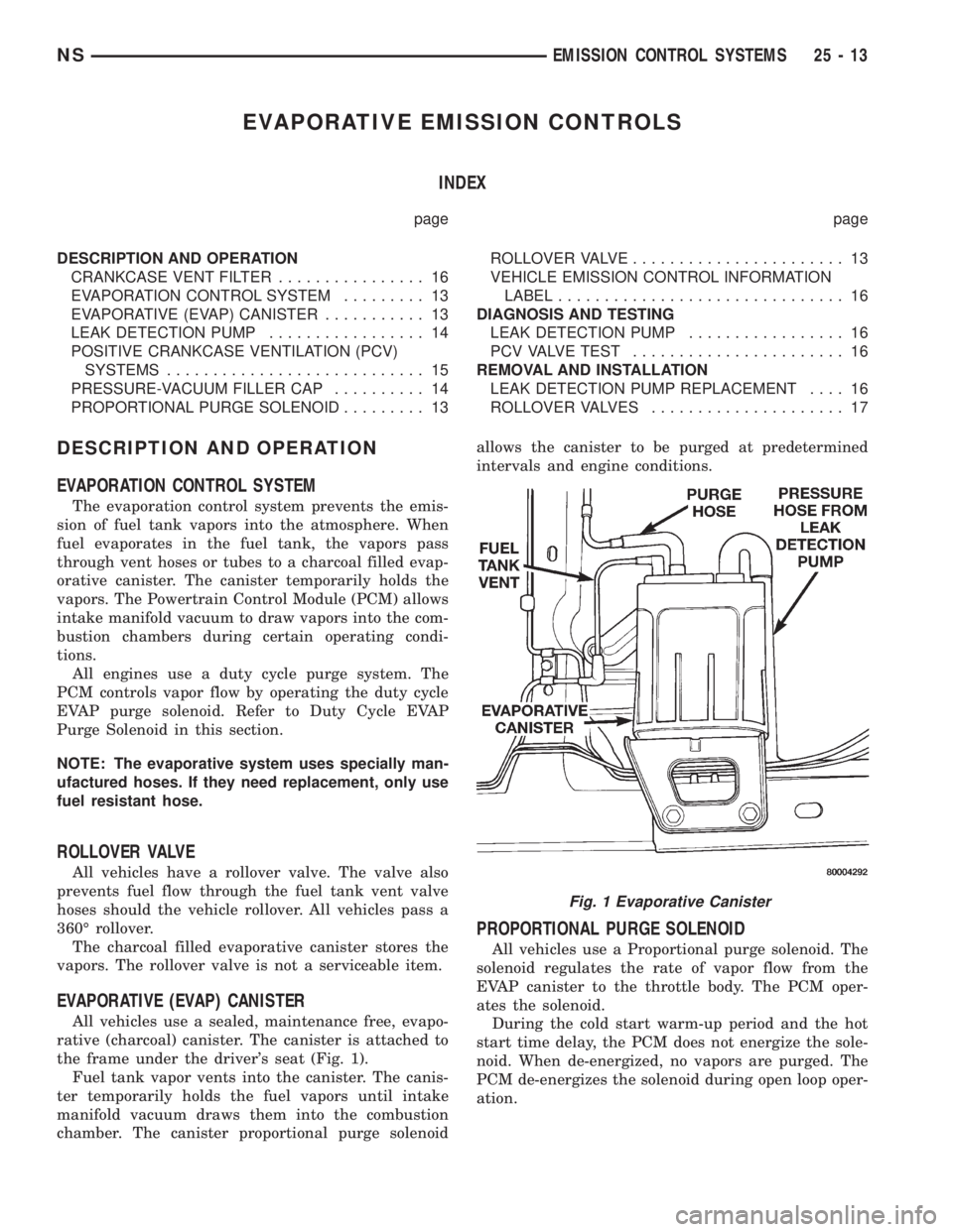
the frame under the driver's seat (Fig. 1).
Fuel tank vapor vents into the canister. The canis-
ter temporarily holds the fuel vapors until intake
manifold vacuum draws them into the combustion
chamber. The canister proportional purge solenoidallows the canister to be purged at predetermined
intervals and engine conditions.
PROPORTIONAL PURGE SOLENOID
All vehicles use a Proportional purge solenoid. The
solenoid regulates the rate of vapor flow from the
EVAP canister to the throttle body. The PCM oper-
ates the solenoid.
During the cold start warm-up period and the hot
start time delay, the PCM does not energize the sole-
noid. When de-energized, no vapors are purged. The
PCM de-energizes the solenoid during open loop oper-
ation.
Fig. 1 Evaporative Canister
NSEMISSION CONTROL SYSTEMS 25 - 13
Page 1918 of 1938
The proportional purge solenoid operates at a fre-
quency of 200hz and is controlled by an engine con-
troller circuit that senses the current being applied
to the proportional purge solenoid and then adjusts
that current to achieve the desired purge flow. The
proportional purge solenoid controls the purge rate of
fuel vapors from the vapor canister and fuel tank to
the engine intake manifold.
PRESSURE-VACUUM FILLER CAP
CAUTION: Remove the fuel filler cap to relieve fuel
tank pressure. The cap must be removed prior to
disconnecting any fuel system component or ser-
vicing the fuel tank.
A pressure-vacuum relief cap seals the fuel tank
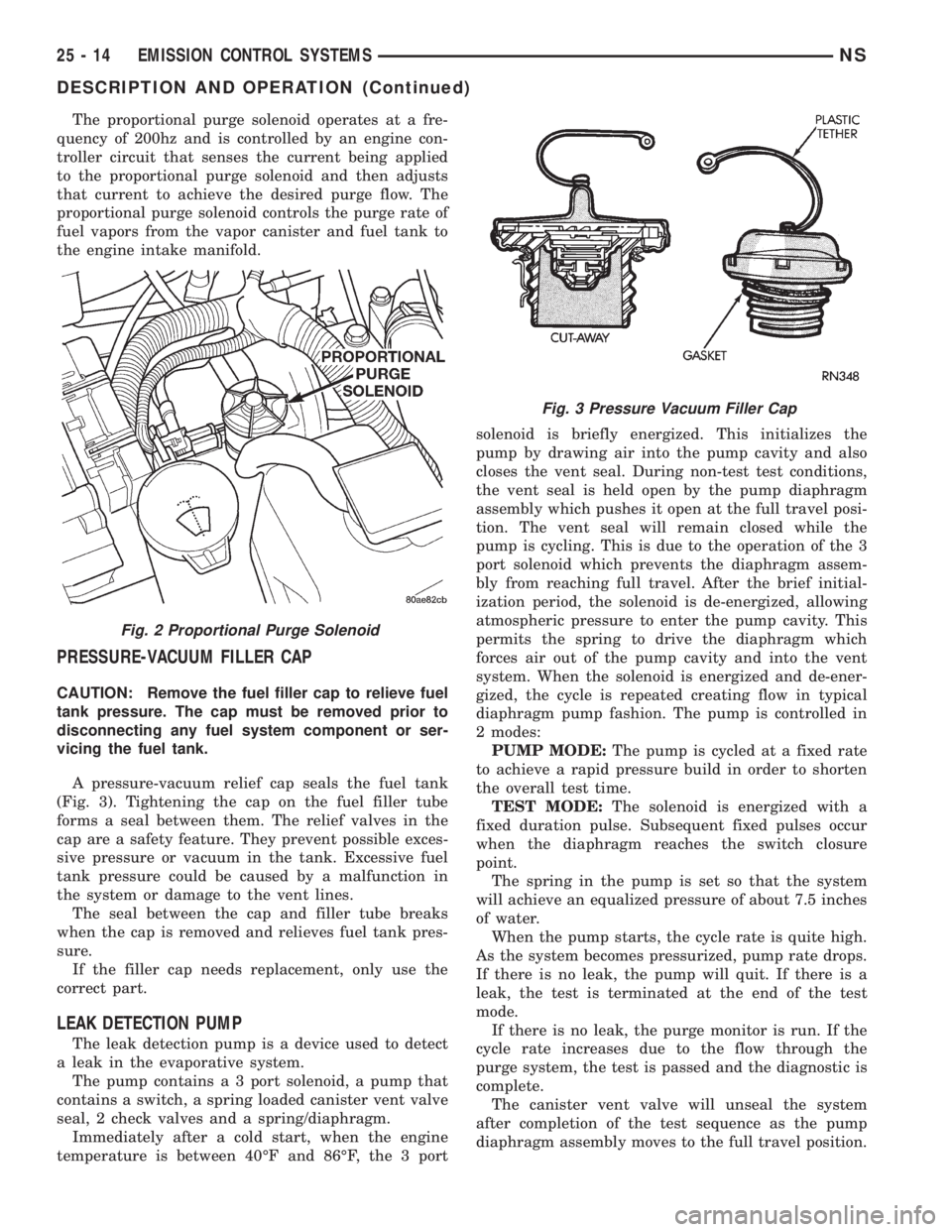
(Fig. 3). Tightening the cap on the fuel filler tube
forms a seal between them. The relief valves in the
cap are a safety feature. They prevent possible exces-
sive pressure or vacuum in the tank. Excessive fuel
tank pressure could be caused by a malfunction in
the system or damage to the vent lines.
The seal between the cap and filler tube breaks
when the cap is removed and relieves fuel tank pres-
sure.
If the filler cap needs replacement, only use the
correct part.
LEAK DETECTION PUMP
The leak detection pump is a device used to detect
a leak in the evaporative system.
The pump contains a 3 port solenoid, a pump that
contains a switch, a spring loaded canister vent valve
seal, 2 check valves and a spring/diaphragm.
Immediately after a cold start, when the engine
temperature is between 40ÉF and 86ÉF, the 3 portsolenoid is briefly energized. This initializes the
pump by drawing air into the pump cavity and also
closes the vent seal. During non-test test conditions,
the vent seal is held open by the pump diaphragm
assembly which pushes it open at the full travel posi-
tion. The vent seal will remain closed while the
pump is cycling. This is due to the operation of the 3
port solenoid which prevents the diaphragm assem-
bly from reaching full travel. After the brief initial-
ization period, the solenoid is de-energized, allowing
atmospheric pressure to enter the pump cavity. This
permits the spring to drive the diaphragm which
forces air out of the pump cavity and into the vent
system. When the solenoid is energized and de-ener-
gized, the cycle is repeated creating flow in typical
diaphragm pump fashion. The pump is controlled in
2 modes:
PUMP MODE:The pump is cycled at a fixed rate
to achieve a rapid pressure build in order to shorten
the overall test time.
TEST MODE:The solenoid is energized with a
fixed duration pulse. Subsequent fixed pulses occur
when the diaphragm reaches the switch closure
point.
The spring in the pump is set so that the system
will achieve an equalized pressure of about 7.5 inches
of water.
When the pump starts, the cycle rate is quite high.
As the system becomes pressurized, pump rate drops.
If there is no leak, the pump will quit. If there is a
leak, the test is terminated at the end of the test
mode.
If there is no leak, the purge monitor is run. If the
cycle rate increases due to the flow through the
purge system, the test is passed and the diagnostic is
complete.
The canister vent valve will unseal the system
after completion of the test sequence as the pump
diaphragm assembly moves to the full travel position.
Fig. 2 Proportional Purge Solenoid
Fig. 3 Pressure Vacuum Filler Cap
25 - 14 EMISSION CONTROL SYSTEMSNS
DESCRIPTION AND OPERATION (Continued)
Page 1922 of 1938
EXHAUST GAS RECIRCULATION (EGR) SYSTEM
INDEX
page page
DESCRIPTION AND OPERATION
GENERAL INFORMATION................. 18
DIAGNOSIS AND TESTING
EGR GAS FLOW TEST................... 20
EGR SYSTEM ON-BOARD DIAGNOSTICS..... 19
EGR SYSTEM TEST..................... 19
EGR VALVE CONTROL (TRANSDUCER) TEST . 21
EGR VALVE LEAKAGE TEST............... 20REMOVAL AND INSTALLATION
EGR TUBE SERVICEÐ3.0L ENGINES........ 22
EGR TUBE SERVICEÐ3.3/3.8L ENGINES..... 22
EGR VALVE SERVICEÐ3.0L ENGINES....... 21
EGR VALVE SERVICEÐ3.3/3.8L ENGINES.... 22
SPECIAL TOOLS
EMISSION CONTROL SYSTEM............. 23
DESCRIPTION AND OPERATION
GENERAL INFORMATION
Refer to Monitored Systems - EGR Monitor in this
group for more information.
The 3.0, 3.3, and 3.8L engines use Exhaust Gas
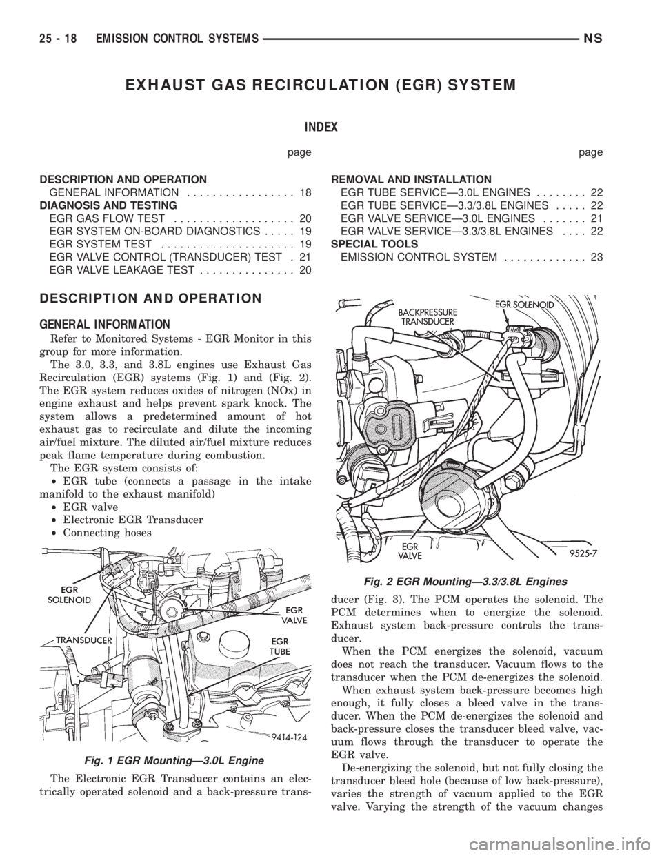
Recirculation (EGR) systems (Fig. 1) and (Fig. 2).
The EGR system reduces oxides of nitrogen (NOx) in
engine exhaust and helps prevent spark knock. The
system allows a predetermined amount of hot
exhaust gas to recirculate and dilute the incoming
air/fuel mixture. The diluted air/fuel mixture reduces
peak flame temperature during combustion.
The EGR system consists of:
²EGR tube (connects a passage in the intake
manifold to the exhaust manifold)
²EGR valve
²Electronic EGR Transducer
²Connecting hoses
The Electronic EGR Transducer contains an elec-
trically operated solenoid and a back-pressure trans-ducer (Fig. 3). The PCM operates the solenoid. The
PCM determines when to energize the solenoid.
Exhaust system back-pressure controls the trans-
ducer.
When the PCM energizes the solenoid, vacuum
does not reach the transducer. Vacuum flows to the
transducer when the PCM de-energizes the solenoid.
When exhaust system back-pressure becomes high
enough, it fully closes a bleed valve in the trans-
ducer. When the PCM de-energizes the solenoid and
back-pressure closes the transducer bleed valve, vac-
uum flows through the transducer to operate the
EGR valve.
De-energizing the solenoid, but not fully closing the
transducer bleed hole (because of low back-pressure),
varies the strength of vacuum applied to the EGR
valve. Varying the strength of the vacuum changes
Fig. 1 EGR MountingÐ3.0L Engine
Fig. 2 EGR MountingÐ3.3/3.8L Engines
25 - 18 EMISSION CONTROL SYSTEMSNS
Page 1929 of 1938
EMISSION CONTROL SYSTEM
CONTENTS
page page
EMISSION CONTROL SYSTEMÐ
2.0L ENGINE.......................... 9
EXHAUST EMISSION CONTROLSÐ
2.5L DIESEL ENGINE................... 5ON-BOARD DIAGNOSTICSÐ
2.5L DIESEL ENGINE................... 1
ON-BOARD DIAGNOSTICSÐ2.5L DIESEL ENGINE
INDEX
page page
GENERAL INFORMATION
SYSTEM DESCRIPTIONÐ
2.5L DIESEL ENGINE................... 1DESCRIPTION AND OPERATION
DIAGNOSTIC TROUBLE CODES............ 2
GENERAL INFORMATION
SYSTEM DESCRIPTIONÐ2.5L DIESEL ENGINE
The 2.5L diesel Powertrain Control Module (PCM)
monitors and controls many different circuits in the
fuel injection pump and engine systems. If the PCM
senses a problem with a monitored circuit that indi-
cates an actual problem, a Diagnostic Trouble Code
(DTC) will be stored in the PCM's memory, and even-
tually will illuminate the Diesel Glow Plug lamp con-
stantly while the key is on. If the problem is
repaired, or is intermittent, the PCM will erase the
DTC after 40 warm-up cycles. A warm-up cycle con-
sists of starting the vehicle when the engine is cold,
then the engine to warms up to a certain tempera-
ture, and finally, the engine temperature falls to a
normal operating temperature, then the key is
turned off.
Certain criteria must be met for a DTC to be
entered into PCM memory. The criteria may be a
specific range of engine rpm, engine or fuel tempera-
ture and/or input voltage to the PCM. A DTC indi-
cates that the PCM has identified an abnormal
signal in a circuit or the system. A DTC may indicate
the result of a failure, but never identify the failed
component directly.
There are several operating conditions that the
PCM does not monitor and set a DTC for. Refer to
the following Monitored Circuits and Non±Monitored
Circuits in this section.
MONITORED CIRCUITS
The PCM can detect certain problems in the elec-
trical system.
Open or Shorted Circuit± The PCM can deter-
mine if sensor output (which is the input to PCM) is
within proper range. It also determines if the circuit
is open or shorted.
Output Device Current Flow± The PCM senses
whether the output devices are electrically connected.
If there is a problem with the circuit, the PCM
senses whether the circuit is open, shorted to ground
(±), or shorted to (+) voltage.
NON±MONITORED CIRCUITS
The PCM does not monitor the following circuits,
systems or conditions that could have malfunctions
that result in driveability problems. A DTC will not
be displayed for these conditions.
Fuel Pressure:Fuel pressure is controlled by the
fuel injection pump. The PCM cannot detect prob-
lems in this component.
Cylinder Compression:The PCM cannot detect
uneven, low, or high engine cylinder compression.
Exhaust System:The PCM cannot detect a
plugged, restricted or leaking exhaust system.
Fuel Injector Malfunctions:The PCM cannot
determine if the fuel injector is clogged, or the wrong
injector is installed. The fuel injectors on the diesel
engine arenot controlledby the PCM, although a
NS/GSEMISSION CONTROL SYSTEM 25 - 1
Page 1930 of 1938

defective fuel injector sensoris monitoredby the
PCM.
Vacuum Assist:Leaks or restrictions in the vac-
uum circuits of vacuum assisted engine control sys-
tem devices are not monitored by the PCM.
PCM System Ground:The PCM cannot deter-
mine a poor system ground. However, a DTC may be
generated as a result of this condition.
PCM Connector Engagement:The PCM cannot
determine spread or damaged connector pins. How-
ever, a DTC may be generated as a result of this con-
dition.
HIGH AND LOW LIMITS
The PCM compares input signal voltages from each
input device. It will establish high and low limits
that are programmed into it for that device. If the
input voltage is not within specifications and other
DTC criteria are met, a DTC will be stored in mem-
ory. Other DTC criteria might include engine rpm
limits or input voltages from other sensors or
switches. The other inputs might have to be sensed
by the PCM when it senses a high or low input volt-
age from the control system device in question.
DESCRIPTION AND OPERATION
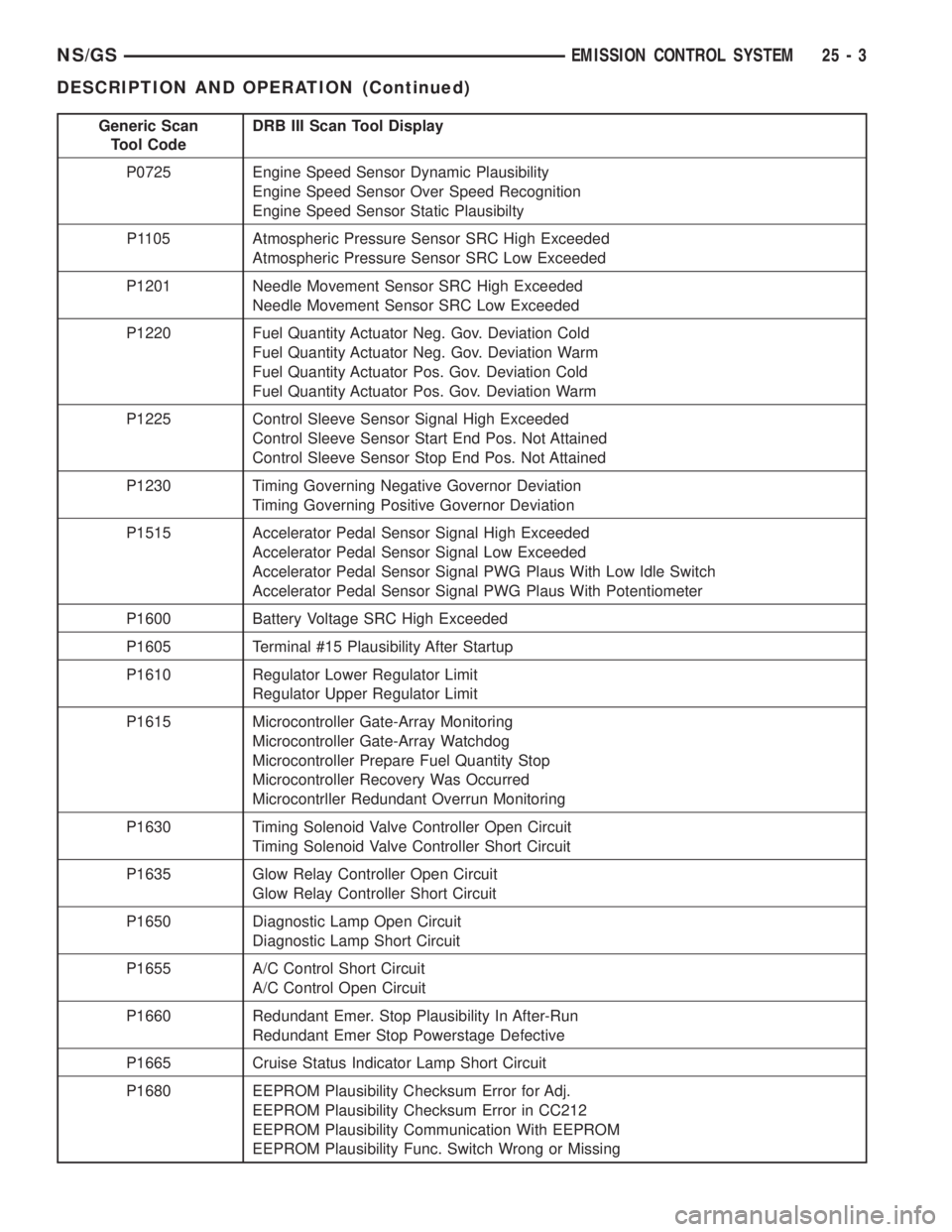
DIAGNOSTIC TROUBLE CODES
On the following pages, a list of DTC's is provided
for the 2.5L diesel engine. A DTC indicates that the
PCM has recognized an abnormal signal in a circuitor the system. A DTC may indicate the result of a
failure, but most likely will not identify the failed
component directly.
ACCESSING DIAGNOSTIC TROUBLE CODES
A stored DTC can be displayed through the use of
the DRB III scan tool. The DRB III connects to the
data link connector. The data link connector is
located under the instrument panel near bottom of
the steering column (Fig. 1).
ERASING TROUBLE CODES
After the problem has been repaired, use the DRB
III scan tool to erase a DTC.
Generic Scan
Tool CodeDRB III Scan Tool Display
P1112 Boost Pressure Sensor Signal High
Boost Pressure Sensor Signal Low
Boost Pressure Sensor Supply High
Boost Pressure Sensor Supply Low
Boost Pressure Sensor Plausibility
P0110 Intake Air Temperature Sensor Signal High
Intake Air Temperature Sensor Signal Low
P1685 Immobilizer Signal Lost
Invalid SKIM Message
P0115 Temperature of Engine Coolant SRC High Exceeded
Temperature of Engine Coolant SRC Low Exceeded
P0180 Fuel Temperature Sensor SRC High Exceeded
Fuel Temperature Sensor SRC Low Exceeded
P0400 EGR Open Circuit
EGR Short Circuit
P0500 Vehicle Speed Sensor PEC Frequency Too High
Vehicle Speed Sensor Signal SRC High Exceeded
Fig. 1 Data Link Connector LocationÐTypical
25 - 2 EMISSION CONTROL SYSTEMNS/GS
GENERAL INFORMATION (Continued)
Page 1931 of 1938
Generic Scan
Tool CodeDRB III Scan Tool Display
P0725 Engine Speed Sensor Dynamic Plausibility
Engine Speed Sensor Over Speed Recognition
Engine Speed Sensor Static Plausibilty
P1105 Atmospheric Pressure Sensor SRC High Exceeded
Atmospheric Pressure Sensor SRC Low Exceeded
P1201 Needle Movement Sensor SRC High Exceeded
Needle Movement Sensor SRC Low Exceeded
P1220 Fuel Quantity Actuator Neg. Gov. Deviation Cold
Fuel Quantity Actuator Neg. Gov. Deviation Warm
Fuel Quantity Actuator Pos. Gov. Deviation Cold
Fuel Quantity Actuator Pos. Gov. Deviation Warm
P1225 Control Sleeve Sensor Signal High Exceeded
Control Sleeve Sensor Start End Pos. Not Attained
Control Sleeve Sensor Stop End Pos. Not Attained
P1230 Timing Governing Negative Governor Deviation
Timing Governing Positive Governor Deviation
P1515 Accelerator Pedal Sensor Signal High Exceeded
Accelerator Pedal Sensor Signal Low Exceeded
Accelerator Pedal Sensor Signal PWG Plaus With Low Idle Switch
Accelerator Pedal Sensor Signal PWG Plaus With Potentiometer
P1600 Battery Voltage SRC High Exceeded
P1605 Terminal #15 Plausibility After Startup
P1610 Regulator Lower Regulator Limit
Regulator Upper Regulator Limit
P1615 Microcontroller Gate-Array Monitoring
Microcontroller Gate-Array Watchdog
Microcontroller Prepare Fuel Quantity Stop
Microcontroller Recovery Was Occurred
Microcontrller Redundant Overrun Monitoring
P1630 Timing Solenoid Valve Controller Open Circuit
Timing Solenoid Valve Controller Short Circuit
P1635 Glow Relay Controller Open Circuit
Glow Relay Controller Short Circuit
P1650 Diagnostic Lamp Open Circuit
Diagnostic Lamp Short Circuit
P1655 A/C Control Short Circuit
A/C Control Open Circuit
P1660 Redundant Emer. Stop Plausibility In After-Run
Redundant Emer Stop Powerstage Defective
P1665 Cruise Status Indicator Lamp Short Circuit
P1680 EEPROM Plausibility Checksum Error for Adj.
EEPROM Plausibility Checksum Error in CC212
EEPROM Plausibility Communication With EEPROM
EEPROM Plausibility Func. Switch Wrong or Missing
NS/GSEMISSION CONTROL SYSTEM 25 - 3
DESCRIPTION AND OPERATION (Continued)