recommended oil CHRYSLER VOYAGER 1996 Owner's Manual
[x] Cancel search | Manufacturer: CHRYSLER, Model Year: 1996, Model line: VOYAGER, Model: CHRYSLER VOYAGER 1996Pages: 1938, PDF Size: 55.84 MB
Page 1057 of 1938
ENGINE DIAGNOSIS
INDEX
page page
DIAGNOSIS AND TESTING
CYLINDER COMBUSTION
PRESSURE LEAKAGE TEST.............. 8
CYLINDER COMPRESSION PRESSURE TEST . . 7
ENGINE DIAGNOSISÐMECHANICAL......... 12
ENGINE DIAGNOSISÐPERFORMANCE...... 10GENERAL INFORMATION.................. 7
INSPECTION
(ENGINE OIL LEAKS IN GENERAL)......... 8
INTAKE MANIFOLD LEAKAGE DIAGNOSIS..... 7
LASH ADJUSTER (TAPPET)
NOISE DIAGNOSIS...................... 8
DIAGNOSIS AND TESTING
GENERAL INFORMATION
Engine diagnosis is helpful in determining the
causes of malfunctions.
These malfunctions may be classified as either
mechanical (e.g., a strange noise), or performance
(e.g., engine idles rough and stalls).
Refer to the Service DiagnosisÐMechanical Chart
and the Service DiagnosisÐPerformance Chart, for
possible causes and corrections of malfunctions. Refer
to Group 14, Fuel System, for the fuel system diag-
nosis.
Additional tests and diagnostic procedures may be
necessary for specific engine malfunctions that can-
not be isolated with the Service Diagnosis charts.
Information concerning additional tests and diagno-
sis is provided within the following:
²Cylinder Compression Pressure Test
²Cylinder Combustion Pressure Leakage Test
²Engine Cylinder Head Gasket Failure Diagnosis
²Intake Manifold Leakage Diagnosis
INTAKE MANIFOLD LEAKAGE DIAGNOSIS
An intake manifold air leak is characterized by
lower than normal manifold vacuum. Also, one or
more cylinders may not be functioning.
WARNING: USE EXTREME CAUTION WHEN THE
ENGINE IS OPERATING. DO NOT STAND IN A
DIRECT LINE WITH THE FAN. DO NOT PUT YOUR
HANDS NEAR THE PULLEYS, BELTS OR THE FAN.
DO NOT WEAR LOOSE CLOTHING.
(1) Start the engine.
(2) Spray a small stream of water (Spray Bottle) at
the suspected leak area.
(3) If a change in RPM'S, the area of the suspected
leak has been found.
(4) Repair as required.
CYLINDER COMPRESSION PRESSURE TEST
The results of a cylinder compression pressure test
can be utilized to diagnose several engine malfunc-
tions.
Ensure the battery is completely charged and the
engine starter motor is in good operating condition.
Otherwise the indicated compression pressures may
not be valid for diagnosis purposes.
(1) Check engine oil level and add oil if necessary.
(2) Drive the vehicle until engine reaches normal
operating temperature. Select a route free from traf-
fic and other forms of congestion, observe all traffic
laws, and accelerate through the gears several times
briskly.
(3) Remove all spark plugs from engine. As spark
plugs are being removed, check electrodes for abnor-
mal firing indicators fouled, hot, oily, etc. Record cyl-
inder number of spark plug for future reference.
(4) Disconnect coil wire from distributor and
secure to good ground to prevent a spark from start-
ing a fire (Conventional Ignition System). For Direct
Ignition System DIS disconnect the coil connector.
(5) Be sure throttle blade is fully open during the
compression check.
(6) Insert compression gage adaptor into the #1
spark plug hole in cylinder head. Crank engine until
maximum pressure is reached on gage. Record this
pressure as #1 cylinder pressure.
(7) Repeat the previous step for all remaining cyl-
inders.
(8) Compression should not be less than (689kPa)
100 psi and not vary more than 25 percent from cyl-
inder to cylinder.
(9) If one or more cylinders have abnormally low
compression pressures, repeat the compression test.
(10) If the same cylinder or cylinders repeat an
abnormally low reading on the second compression
test, it could indicate the existence of a problem in
the cylinder in question.The recommended com-
pression pressures are to be used only as a
guide to diagnosing engine problems. An engine
should not be disassembled to determine the
NSENGINE 9 - 7
Page 1059 of 1938
(2) Add an oil soluble dye (use as recommended by
manufacturer). Start the engine and let idle for
approximately 15 minutes. Check the oil dipstick to
make sure the dye is thoroughly mixed as indicated
with a bright yellow color under a black light.
(3) Using a black light, inspect the entire engine
for fluorescent dye, particularly at the suspected area
of oil leak. If the oil leak is found and identified,
repair per service manual instructions.
(4) If dye is not observed, drive the vehicle at var-
ious speeds for approximately 24km (15 miles), and
repeat inspection.
(5)If the oil leak source is not positively
identified at this time, proceed with the air leak
detection test method as follows:
(6) Disconnect the fresh air hose (makeup air) at
the cylinder head cover and plug or cap the nipple on
the cover.
(7) Remove the PCV valve hose from the cylinder
head cover. Cap or plug the PCV valve nipple on the
cover.
(8) Attach an air hose with pressure gauge and
regulator to the dipstick tube.
CAUTION: Do not subject the engine assembly to
more than 20.6 kpa (3 PSI) of test pressure.
(9) Gradually apply air pressure from 1 psi to 2.5
psi maximum while applying soapy water at the sus-
pected source. Adjust the regulator to the suitable
test pressure that provide the best bubbles which
will pinpoint the leak source. If the oil leak is
detected and identified, repair per service manual
procedures.
(10) If the leakage occurs at the rear oil seal area,
refer to the section, Inspection for Rear Seal Area
Leak.
(11) If no leaks are detected, turn off the air sup-
ply and remove the air hose and all plugs and caps.
Install the PCV valve and breather cap hose. Proceed
to next step.
(12) Clean the oil off the suspect oil leak area
using a suitable solvent. Drive the vehicle at various
speeds approximately 24 km (15 miles). Inspect the
engine for signs of an oil leak by using a black light.INSPECTION FOR REAR SEAL AREA LEAKS
Since it is sometimes difficult to determine the
source of an oil leak in the rear seal area of the
engine, a more involved inspection is necessary. The
following steps should be followed to help pinpoint
the source of the leak.
If the leakage occurs at the crankshaft rear oil seal
area:
(1) Disconnect the battery.
(2) Raise the vehicle.
(3) Remove torque converter or clutch housing
cover and inspect rear of block for evidence of oil.
Use a black light to check for the oil leak. If a leak is
present in this area remove transmission for further
inspection.
(a) Circular spray pattern generally indicates
seal leakage or crankshaft damage.
(b) Where leakage tends to run straight down,
possible causes are a porous block, oil galley cup
plug, bedplate to cylinder block mating surfaces
and seal bore. See proper repair procedures for
these items.
(4) If no leaks are detected, pressurized the crank-
case as outlined in the, Inspection (Engine oil Leaks
in general)
CAUTION: Do not exceed 20.6 kPa (3 psi).
(5) If the leak is not detected, very slowly turn the
crankshaft and watch for leakage. If a leak is
detected between the crankshaft and seal while
slowly turning the crankshaft, it is possible the
crankshaft seal surface is damaged. The seal area on
the crankshaft could have minor nicks or scratches
that can be polished out with emery cloth.
CAUTION: Use extreme caution when crankshaft
polishing is necessary to remove minor nicks and
scratches. The crankshaft seal flange is especially
machined to complement the function of the rear oil
seal.
(6) For bubbles that remain steady with shaft
rotation, no further inspection can be done until dis-
assembled.
(7) After the oil leak root cause and appropriate
corrective action have been identified. Refer to Rear
Crankshaft Seals, for proper replacement procedures.
NSENGINE 9 - 9
DIAGNOSIS AND TESTING (Continued)
Page 1066 of 1938

sealing and a chrome plated taper faced intermediate
ring for additional cylinder pressure control. There
are also standard oil control rings.
CYLINDER HEAD:Features a Dual Over Head
Camshaft (DOHC) 4 valves per cylinder cross flow
design. The valves are arranged in two inline banks,
with the ports of the bank of two intake valves per
cylinder facing toward the radiator side of engine
and ports of the bank of two exhaust valves per cyl-
inder facing toward the dash panel. Incorporates
powder metal valve guides and seats. Integral oil gal-
leys within the cylinder head supplies oil to the
hydraulic lash adjusters, camshaft and valve mecha-
nisms.
CAMSHAFTS:The nodular iron camshafts have
six bearing journals and 2 cam lobes per cylinder.
Flanges at the rear journals control camshaft end
play. Provision for cam position sensor is located on
the intake camshaft at the rear of cylinder head. A
hydrodynamic oil seal is used for oil control at the
front of the camshaft.
VALVES:4 valves per cylinder are actuated by
roller cam followers which pivot on stationary
hydraulic lash adjusters. All valves have 6 mm diam-
eter chrome plated valve stems. The valve sizes are
34.8 mm (1.370 inch.) diameter intake valves and
30.5 mm (1.20 inch.) diameter exhaust valves. Viton
rubber valve stem seals are integral with the spring
seats. Valve springs, spring retainers, and locks are
conventional.
INTAKE MANIFOLD:The intake manifold is a
two piece aluminum casting, attached to the cylinder
head with ten screws. This long branch fan design
enhances low and midspeed torque, while minimizing
undesirable inlet noise.
EXHAUST MANIFOLD:The exhaust manifold is
made of cast iron for strength and high tempera-
tures.
ENGINE LUBRICATION:Refer to Group 0
Lubrication and Maintenance for recommended oil to
be used in various engine application. System is full
flow filtration, pressure feed type. The oil pump is
mounted in the front engine cover and driven by the
crankshaft. Pressurized oil is then routed through
the main oil gallery, running the length of the cylin-
der block, supplying main and rod bearings with fur-
ther routing. Pistons are lubricated from rod bearing
throw off and lubricating slots on the connecting rod
assemblies. Camshaft and valve mechanisms are
lubricated from a full length cylinder head oil gallery
supplied from the crankcase main oil gallery.DIAGNOSIS AND TESTING
CHECKING ENGINE OIL PRESSURE
(1) Remove oil pressure sending unit and install
gauge assembly C-3292.
(2) Run engine until thermostat opens.
CAUTION: If oil pressure is 0 at idle, Do Not Run
engine at 3000 RPM
(3) Oil Pressure:Curb Idle25 kPa (4 psi) mini-
mum3000 RPM170/550 kPa (25/80 psi).
(4) If oil pressure is 0 at idle. Shut off engine,
check for pressure relief valve stuck open or a
clogged oil pickup screen.
SERVICE PROCEDURES
FITTING PISTONS
Piston and cylinder wall must be clean and dry.
Piston diameter should be measured 90 degrees to
piston pin about 14 mm (9/16 inch.) from the bottom
of the skirt as shown in (Fig. 3). Cylinder bores
should be measured halfway down the cylinder bore
and transverse to the engine crankshaft center line
shown in (Fig. 2). Refer to Cylinder Bore and Piston
Specification Chart.
Correct piston to bore clearance must be estab-
lished in order to assure quiet and economical oper-
ation.
Chrysler engines use pistons designed specifically
for each engine model. Clearance and sizing locations
vary with respect to engine model.
NOTE: Pistons and cylinder bores should be mea-
sured at normal room temperature, 70ÉF (21ÉC).
FITTING PISTON RINGS
(1) Wipe cylinder bore clean. Insert ring and push
down with piston to ensure it is square in bore. The
ring gap measurement must be made with the ring
positioning at least 12 mm (0.50 inch) from bottom of
cylinder bore. Check gap with feeler gauge (Fig. 4).
Refer to specification in Piston Ring Specification
Chart.
(2) Check piston ring to groove side clearance (Fig.
5). Refer to specification in Piston Ring Specification
Chart.
9 - 16 2.4L ENGINENS
DESCRIPTION AND OPERATION (Continued)
Page 1068 of 1938
a. Oil ring expander.
b. Upper oil ring side rail.
c. Lower oil ring side rail.
d. No. 2 Intermediate piston ring.
e. No. 1 Upper piston ring.
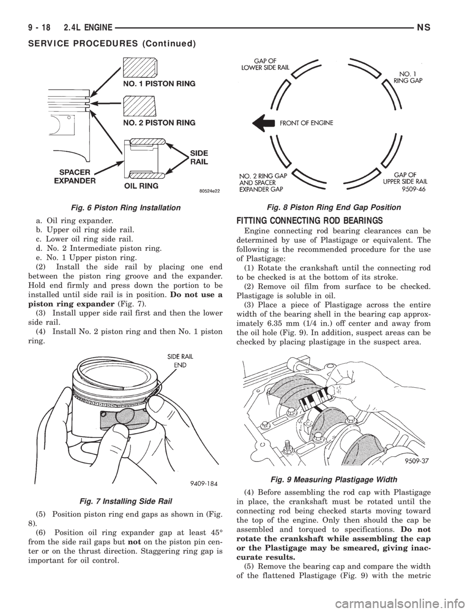
(2) Install the side rail by placing one end
between the piston ring groove and the expander.
Hold end firmly and press down the portion to be
installed until side rail is in position.Do not use a
piston ring expander(Fig. 7).
(3) Install upper side rail first and then the lower
side rail.
(4) Install No. 2 piston ring and then No. 1 piston
ring.
(5) Position piston ring end gaps as shown in (Fig.
8).
(6) Position oil ring expander gap at least 45É
from the side rail gaps butnoton the piston pin cen-
ter or on the thrust direction. Staggering ring gap is
important for oil control.FITTING CONNECTING ROD BEARINGS
Engine connecting rod bearing clearances can be
determined by use of Plastigage or equivalent. The
following is the recommended procedure for the use
of Plastigage:
(1) Rotate the crankshaft until the connecting rod
to be checked is at the bottom of its stroke.
(2) Remove oil film from surface to be checked.
Plastigage is soluble in oil.
(3) Place a piece of Plastigage across the entire
width of the bearing shell in the bearing cap approx-
imately 6.35 mm (1/4 in.) off center and away from
the oil hole (Fig. 9). In addition, suspect areas can be
checked by placing plastigage in the suspect area.
(4) Before assembling the rod cap with Plastigage
in place, the crankshaft must be rotated until the
connecting rod being checked starts moving toward
the top of the engine. Only then should the cap be
assembled and torqued to specifications.Do not
rotate the crankshaft while assembling the cap
or the Plastigage may be smeared, giving inac-
curate results.
(5) Remove the bearing cap and compare the width
of the flattened Plastigage (Fig. 9) with the metric
Fig. 6 Piston Ring Installation
Fig. 7 Installing Side Rail
Fig. 8 Piston Ring End Gap Position
Fig. 9 Measuring Plastigage Width
9 - 18 2.4L ENGINENS
SERVICE PROCEDURES (Continued)
Page 1180 of 1938
GENERAL SPECIFICATION
Type .............In-Line OHV, DOHC & SOHC
Bore.....................87.5mm (3.445 Inch)
Stroke...................83.0mm (3.268 inch)
Compression Ratio....DOHC - 9.6:1 SOHC - 9.8:1
Displacement.........2.0Liters (122 Cubic Inch)
Firing Order........................1,3,4,2
Compression Pressure...........1172-1551 kPa
(170 - 225 psi)
Maximum Variation Between Cylinders......25%
Lubrication . . . Pressure Feed - Full Flow Filtration
(Crankshaft Driven Pump)
Engine Oil Capacity . . Refer to Group 0, Lubrication
and Maintenance
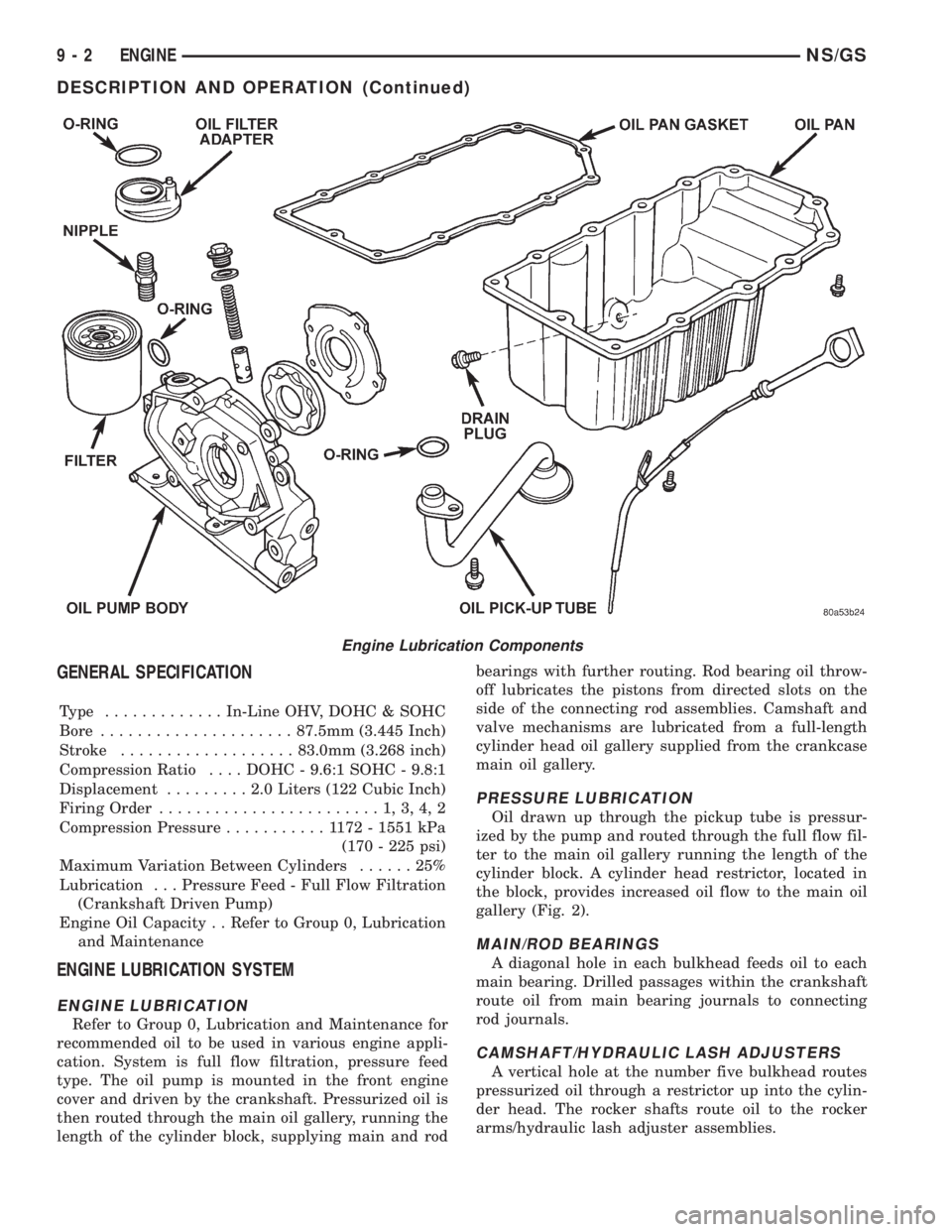
ENGINE LUBRICATION SYSTEM
ENGINE LUBRICATION
Refer to Group 0, Lubrication and Maintenance for
recommended oil to be used in various engine appli-
cation. System is full flow filtration, pressure feed
type. The oil pump is mounted in the front engine
cover and driven by the crankshaft. Pressurized oil is
then routed through the main oil gallery, running the
length of the cylinder block, supplying main and rodbearings with further routing. Rod bearing oil throw-
off lubricates the pistons from directed slots on the
side of the connecting rod assemblies. Camshaft and
valve mechanisms are lubricated from a full-length
cylinder head oil gallery supplied from the crankcase
main oil gallery.
PRESSURE LUBRICATION
Oil drawn up through the pickup tube is pressur-
ized by the pump and routed through the full flow fil-
ter to the main oil gallery running the length of the
cylinder block. A cylinder head restrictor, located in
the block, provides increased oil flow to the main oil
gallery (Fig. 2).
MAIN/ROD BEARINGS
A diagonal hole in each bulkhead feeds oil to each
main bearing. Drilled passages within the crankshaft
route oil from main bearing journals to connecting
rod journals.
CAMSHAFT/HYDRAULIC LASH ADJUSTERS
A vertical hole at the number five bulkhead routes
pressurized oil through a restrictor up into the cylin-
der head. The rocker shafts route oil to the rocker
arms/hydraulic lash adjuster assemblies.
Engine Lubrication Components
9 - 2 ENGINENS/GS
DESCRIPTION AND OPERATION (Continued)
Page 1226 of 1938
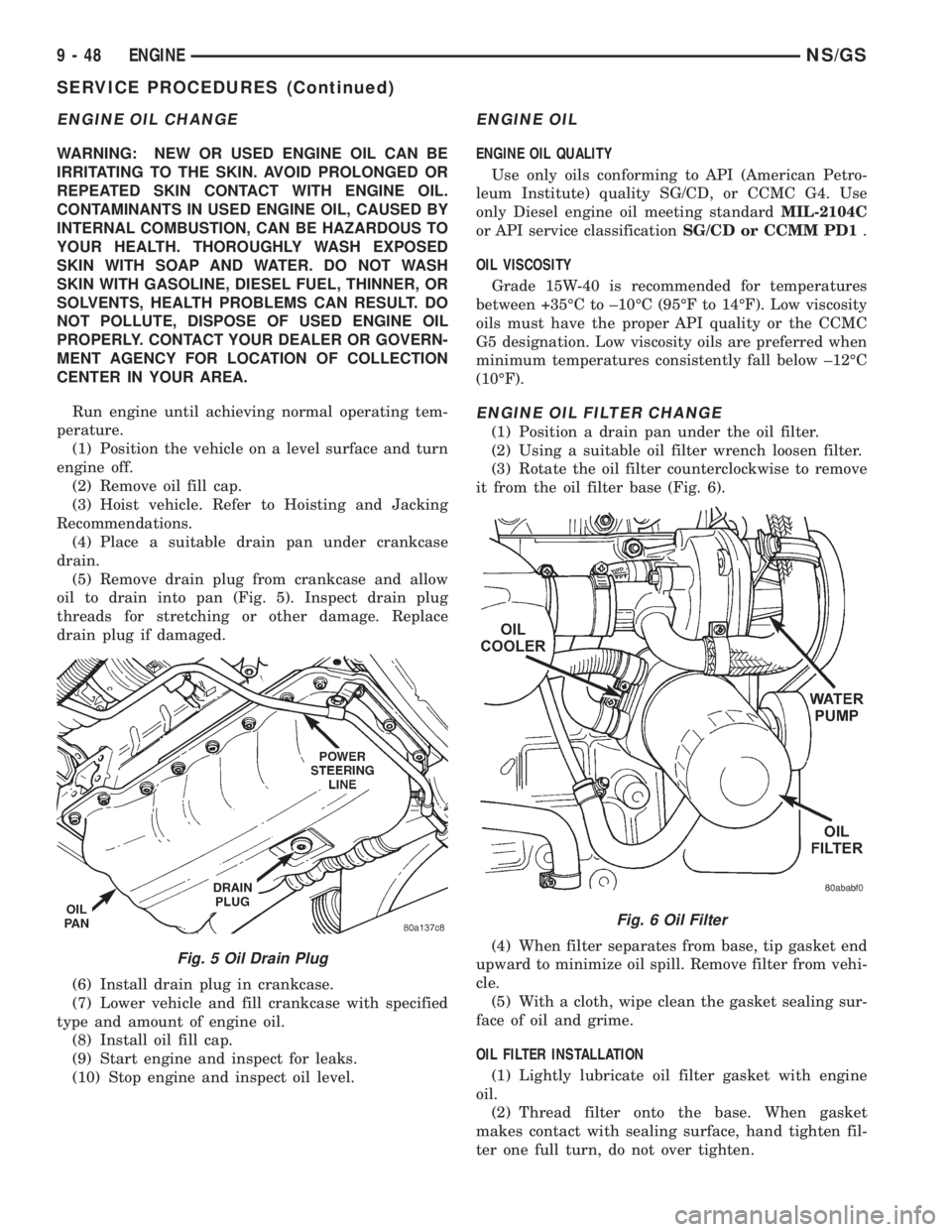
ENGINE OIL CHANGE
WARNING: NEW OR USED ENGINE OIL CAN BE
IRRITATING TO THE SKIN. AVOID PROLONGED OR
REPEATED SKIN CONTACT WITH ENGINE OIL.
CONTAMINANTS IN USED ENGINE OIL, CAUSED BY
INTERNAL COMBUSTION, CAN BE HAZARDOUS TO
YOUR HEALTH. THOROUGHLY WASH EXPOSED
SKIN WITH SOAP AND WATER. DO NOT WASH
SKIN WITH GASOLINE, DIESEL FUEL, THINNER, OR
SOLVENTS, HEALTH PROBLEMS CAN RESULT. DO
NOT POLLUTE, DISPOSE OF USED ENGINE OIL
PROPERLY. CONTACT YOUR DEALER OR GOVERN-
MENT AGENCY FOR LOCATION OF COLLECTION
CENTER IN YOUR AREA.
Run engine until achieving normal operating tem-
perature.
(1) Position the vehicle on a level surface and turn
engine off.
(2) Remove oil fill cap.
(3) Hoist vehicle. Refer to Hoisting and Jacking
Recommendations.
(4) Place a suitable drain pan under crankcase
drain.
(5) Remove drain plug from crankcase and allow
oil to drain into pan (Fig. 5). Inspect drain plug
threads for stretching or other damage. Replace
drain plug if damaged.
(6) Install drain plug in crankcase.
(7) Lower vehicle and fill crankcase with specified
type and amount of engine oil.
(8) Install oil fill cap.
(9) Start engine and inspect for leaks.
(10) Stop engine and inspect oil level.
ENGINE OIL
ENGINE OIL QUALITY
Use only oils conforming to API (American Petro-
leum Institute) quality SG/CD, or CCMC G4. Use
only Diesel engine oil meeting standardMIL-2104C
or API service classificationSG/CD or CCMM PD1.
OIL VISCOSITY
Grade 15W-40 is recommended for temperatures
between +35ÉC to ±10ÉC (95ÉF to 14ÉF). Low viscosity
oils must have the proper API quality or the CCMC
G5 designation. Low viscosity oils are preferred when
minimum temperatures consistently fall below ±12ÉC
(10ÉF).
ENGINE OIL FILTER CHANGE
(1) Position a drain pan under the oil filter.
(2) Using a suitable oil filter wrench loosen filter.
(3) Rotate the oil filter counterclockwise to remove
it from the oil filter base (Fig. 6).
(4) When filter separates from base, tip gasket end
upward to minimize oil spill. Remove filter from vehi-
cle.
(5) With a cloth, wipe clean the gasket sealing sur-
face of oil and grime.
OIL FILTER INSTALLATION
(1) Lightly lubricate oil filter gasket with engine
oil.
(2) Thread filter onto the base. When gasket
makes contact with sealing surface, hand tighten fil-
ter one full turn, do not over tighten.
Fig. 5 Oil Drain Plug
Fig. 6 Oil Filter
9 - 48 ENGINENS/GS
SERVICE PROCEDURES (Continued)
Page 1477 of 1938
If there is any doubt about its condition, drain out a
sample for a double check.
SELECTION OF LUBRICANT
It is important that the proper lubricant be used in
these transmissions. Mopar ATF PLUS 3 (Automatic
Transmission Fluid- type 7176) should be used to aid
in ensuring optimum transmission performance. It is
important that the transmission fluid be maintained
at the prescribed level using the recommended fluids.
SPECIAL ADDITIVES
Chrysler Corporation does not recommend the
addition of any fluids to the transmission, other than
fluid listed above. An exception to this policy is the
use of special dyes to aid in detecting fluid leaks. The
use of transmission sealers should be avoided, since
they may adversely affect seals.
DESCRIPTION AND OPERATION
TORQUE CONVERTER CLUTCH
A torque converter clutch is standard on all vehi-
cles. The torque converter clutch is activated only in
direct drive and is controlled by the engine electron-
ics. A solenoid on the valve body, is powered by the
powertrain control module to activate torque con-
verter clutch.
HYDRAULIC CONTROL SYSTEM
The hydraulic control system makes the transaxle
fully automatic, and has four important functions to
perform. The components of any automatic control
system may be grouped into the following basic
groups:
The pressure supply system, the pressure regulat-
ing valves, the flow control valves, the clutches, and
band servos.
Taking each of these basic groups or systems in
turn, the control system may be described as follows:
PRESSURE SUPPLY SYSTEM
The pressure supply system consists of an oil pump
driven by the engine through the torque converter.
The single pump furnishes pressure for all the
hydraulic and lubrication requirements.Oil pump
housing assemblies are available with prese-
lected pump gears.
PRESSURE REGULATING VALVES
The pressure regulating valve controls line pres-
sure dependent on throttle opening. The governor
valve transmits regulated pressure to the valve body
(in conjunction with vehicle speed) to control upshift
and downshift.The throttle valve transmits regulated pressure to
the transaxle (dependent on throttle position) to con-
trol upshift and downshift.
FLOW CONTROL VALVES
The manual valve provides the different transaxle
drive ranges as selected by the vehicle operator.
The 1-2 shift valve automatically shifts the tran-
saxle from first to second or from second to first,
depending on the vehicle operation.
The 2-3 shift valve automatically shifts the tran-
saxle from second to third or from third to second
depending on the vehicle operation.
The kickdown valve makes possible a forced down-
shift from third to second, second to first, or third to
first (depending on vehicle speed). This can be done
by depressing the accelerator pedal past the detent
feel near wide open throttle.
The shuttle valve has two separate functions and
performs each independently of the other. The first is
providing fast release of the kickdown band, and
smooth front clutch engagement when a lift-foot
upshift from second to third is made. The second
function is to regulate the application of the kick-
down servo and band when making third to second
kickdown.
The by-pass valve provides for smooth application
of the kickdown band on 1-2 upshifts.
The torque converter clutch solenoid allows for the
electronic control of the torque converter clutch. It
also disengages the torque converter at closed throt-
tle. This is done during engine warm-up, and part-
throttle acceleration.
The switch valve directs oil to apply the torque
converter clutch in one position. The switch valve
releases the torque converter clutch in the other posi-
tion.
CLUTCHES, BAND SERVOS, AND ACCUMULATOR
The front and rear clutch pistons, and both servo
pistons are moved hydraulically to engage the
clutches and apply the bands. The pistons are
released by spring tension when hydraulic pressure
is released. On the 2-3 upshift, the kickdown servo
piston is released by spring tension and hydraulic
pressure.
The accumulator controls the hydraulic pressure
on the apply side of the kickdown servo during the
1-2 upshift; thereby, cushioning the kickdown band
application at any throttle position.
NSTRANSAXLE AND POWER TRANSFER UNIT 21 - 3
GENERAL INFORMATION (Continued)
Page 1490 of 1938
SERVICE PROCEDURES
FLUID AND FILTER CHANGE
When the factory fill fluid is changed, only fluids
labeled MOPARtATF PLUS 3 (Automatic Transmis-
sion fluid) Type 7176 should be used.
If the transaxle is disassembled for any reason, the
fluid and filter should be changed.
30,000 MILE TRANSAXLE OIL CHANGE
When a vehicle attains 30,000 miles on its odome-
ter it is recommended that the transaxle oil be
changed. To change the oil, use the procedure that
follows:
It is recommended that a transaxle fluid exchanger
(ATF 2000+ or equivalent) be used to replace the
used fluid in the transaxle. If a fluid exchanger is not
available use a fluid suction pump (Vaculayor equiv-
alent) to draw the fluid out of the dipstick tube. If a
fluid suction pump is not available remove the oil
pan and drain the fluid.
CAUTION: Chrysler Corporation does not recom-
mend using any fluid exchanger that introduces
additives into the transaxle.TRANSAXLE FLUID EXCHANGER METHOD
(1) To perform the transaxle fluid exchange, the
transaxle must be at operating temperature. Drive
the vehicle till it reaches full operating temperature.
(2) Verify that the fill tank on the transaxle fluid
exchanger (ATF 2000+ or equivalent) is clean and
dry.
(3) Fill the tank to the recommended fill capacity
with Mopar ATF Plus 3 Type 7176.
(4) Hookup the vehicle to the machine following
the manufacturers instructions. Perform the
exchange procedure following the instructions pro-
vided with the machine.
(5) Once machine has completed the fluid
exchange. Check the fluid level and condition and fill
to proper level with Mopar ATF Plus 3 Type 7176.
NOTE: Verify that the transaxle cooler lines are
tightened to proper specifications. Cooler line
torque specification is 2 N²m (18 in. lbs.).
DIPSTICK TUBE FLUID SUCTION METHOD
(1) When performing the fluid suction method,
make sure the transaxle is at full operating temper-
ature.
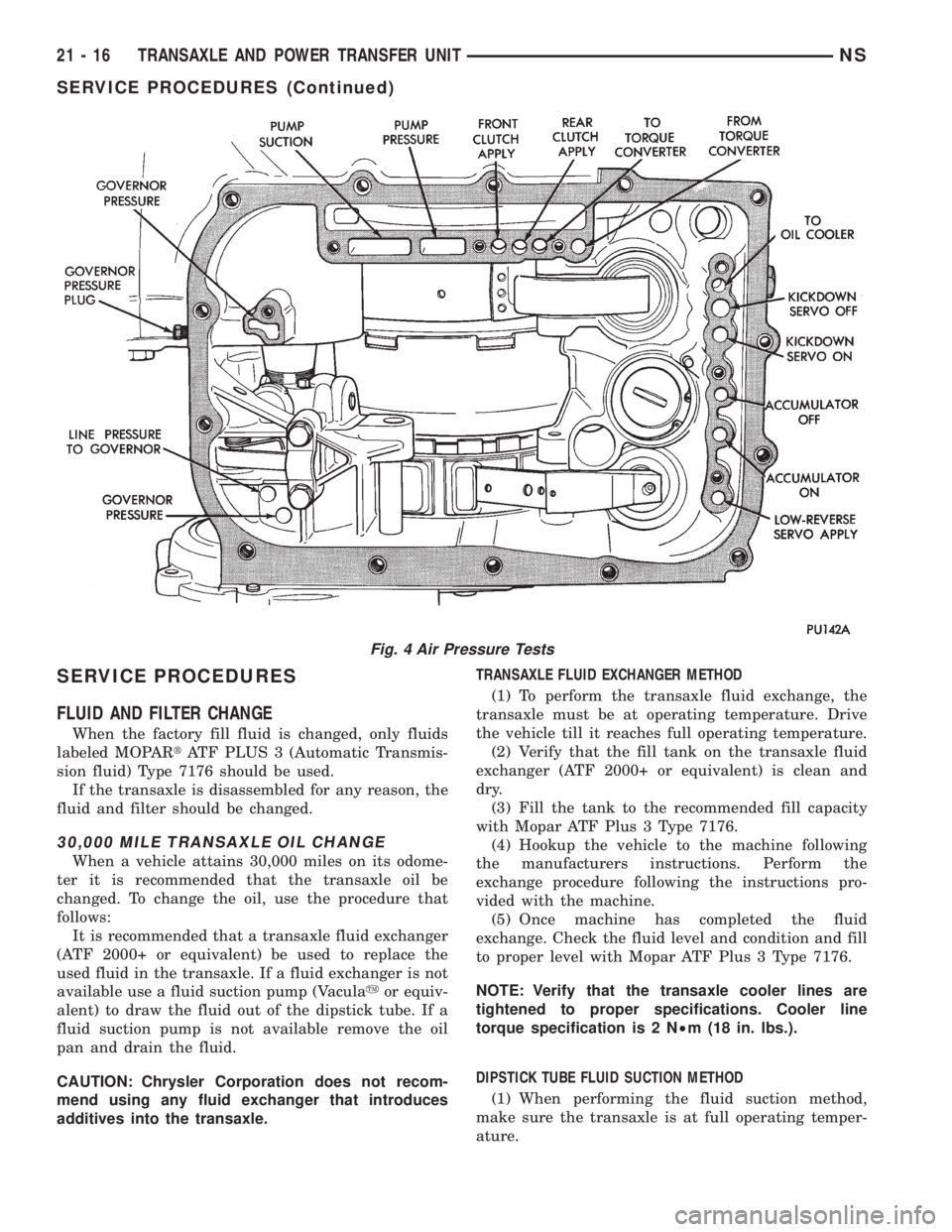
Fig. 4 Air Pressure Tests
21 - 16 TRANSAXLE AND POWER TRANSFER UNITNS
SERVICE PROCEDURES (Continued)
Page 1491 of 1938
(2) To perform the dipstick tube fluid suction
method, use a suitable fluid suction device (Vaculay
or equivalent).
(3) Insert the fluid suction line into the dipstick
tube.
NOTE: Verify that the suction line is inserted to the
lowest point of the transaxle oil pan. This will
ensure complete evacuation of the fluid in the pan.
(4) Follow the manufacturers recommended proce-
dure and evacuate the fluid from the transaxle.
(5) Remove the suction line from the dipstick tube.
(6) Add 4 Quarts of Mopar ATF Plus 3 Type 7176
transaxle fluid.
(7) Start the engine and allow it to idle for a min-
imum of one minute. With the parking brake applied,
press your foot on the service brake and cycle the
transaxle from park to all gear positions ending in
neutral or park.
(8) Check the transaxle fluid level and add an
appropriate amount to bring the transaxle fluid level
to 3mm (1/8 in.) below the ADD mark on the dip-
stick.
(9) Recheck the fluid level after the transaxle is at
normal operating temperature. The level should be in
the HOT range.
TRANSAXLE OIL PAN DROP METHOD
This procedure involves removing the transaxle oil
pan to drain the transaxle fluid.
(1) Bring the vehicle up to normal operating tem-
perature. Drive the vehicle a minimum of 10 miles.
(2) Raise the vehicle on the hoist.
(3) Loosen the transaxle oil pan and drain the
fluid into a suitable container.
(4) Remove the pan and clean all sealant from the
pan and transaxle mating surfaces. Clean the mag-
net and the inside of the pan.
(5) Apply a 1/8 inch bead of Mopar RTV Sealant to
the mounting flange of the transaxle oil pan. Apply
RTV Sealant to the underside of the attaching bolts.
Attach the oil pan to the transaxle. Tighten the bolts
to 19 N²m (165 in. lbs.).
(6) Lower the vehicle and add 4 Quarts of Mopar
ATF Plus 3 Type 7176 transaxle fluid.
(7) Start the engine and allow it to idle for a min-
imum of one minute. With the parking brake applied,
press your foot on the service brake and cycle the
transaxle from park to all gear positions ending in
neutral or park.
(8) Check the transaxle fluid level and add an
appropriate amount to bring the transaxle fluid level
to 3mm (1/8 in.) below the ADD mark on the dip-
stick.
(9) Recheck the fluid level after the transaxle is at
normal operating temperature. The level should be inthe HOT range. Drive the vehicle a minimum of 10
miles.
(10) Raise the vehicle on the hoist.
(11) Check for leaks around the transaxle oil pan
sealing surfaces.
(12) Recheck the fluid level. The level should be in
the HOT range.
SEVERE USAGE SERVICE
If the vehicle exhibits any of the following symp-
toms, it is recommended that the transaxle oil and
filter be replaced.
²Transaxle oil discolored
²Transaxle oil has high mileage
²Oil feels grimy when rubbed between fingertips
²Poor shift quality
²Delayed gear engagement
²Vehicle shudder between shifts
TRANSAXLE OIL AND FILTER REPLACEMENT
This procedure involves changing the transaxle
fluid and filter, driving the vehicle for 10 miles and
changing the transaxle fluid a second time.
(1) Bring the vehicle up to normal operating tem-
perature. Drive the vehicle a minimum of 10 miles.
(2) Raise the vehicle on the hoist.
(3) Loosen the transaxle oil pan and drain the
fluid into a suitable container.
(4) Remove the pan and clean all sealant from the
pan and transaxle mating surfaces. Clean the mag-
net and the inside of the pan.
(5) Separate the filter and O-ring from the valve
body. Inspect the O-ring for cuts or improper instal-
lation. This could lead to delayed garage shifts.
(6) Install a new filter. Replace the O-ring as nec-
essary.
(7) Apply a 1/8 inch bead of Mopar RTV Sealant to
the mounting flange of the transaxle oil pan. Apply
RTV Sealant to the underside of the attaching bolts.
Attach the oil pan to the transaxle. Tighten the bolts
to 19 N²m (165 in. lbs.).
(8) Lower the vehicle and add 4 Quarts of Mopar
ATF Plus 3 Type 7176 transaxle fluid.
(9) Start the engine and allow it to idle for a min-
imum of one minute. With the parking brake applied,
press your foot on the service brake and cycle the
transaxle from park to all gear positions ending in
neutral or park.
(10) Check the transaxle fluid level and add an
appropriate amount to bring the transaxle fluid level
to 3mm (1/8 in.) below the ADD mark on the dip-
stick.
(11) Recheck the fluid level after the transaxle is
at normal operating temperature. The level should be
in the HOT range. Drive the vehicle a minimum of
10 miles.
(12) Raise the vehicle on the hoist.
NSTRANSAXLE AND POWER TRANSFER UNIT 21 - 17
SERVICE PROCEDURES (Continued)
Page 1492 of 1938
(13) Remove the pan and clean all sealant from
the pan and transaxle mating surfaces. Clean the
magnet and the inside of the pan.
(14) Separate the filter from the valve body to
allow additional fluid to drain from the transaxle.
Inspect the filter O-ring for any damage and replace
as necessary.
(15) After the transaxle has stopped draining,
reinstall the filter and O-ring.
(16) Apply a 1/8 inch bead of Mopar RTV Sealant
to the mounting flange of the transaxle oil pan.
Apply RTV Sealant to the underside of the attaching
bolts. Attach the oil pan to the transaxle. Tighten the
bolts to 19 N²m (165 in. lbs.).
(17) Lower the vehicle and add 4 Quarts of Mopar
ATF Plus 3 Type 7176 transaxle fluid.
(18) Start the engine and allow it to idle for a min-
imum of one minute. With the parking brake applied,
press your foot on the service brake and cycle the
transaxle from park to all gear positions ending in
neutral or park.
(19) Check the transaxle fluid level and add an
appropriate amount to bring the transaxle fluid level
to 3mm (1/8 in.) below the ADD mark on the dip-
stick.
(20) Recheck the fluid level after the transaxle is
at normal operating temperature. The level should be
in the HOT range.
FLUID DRAIN AND REFILL
(1) Raise vehicle on a hoist (See Group 0, Lubrica-
tion). Place a drain container with a large opening,
under transaxle oil pan.
(2) Loosen pan bolts and tap the pan at one corner
to break it loose allowing fluid to drain, then remove
the oil pan.
(3) Install a new filter and gasket on bottom of the
valve body and tighten retaining screws to 5 N´m (40
inch-pounds).
(4) Clean the oil pan and magnet. Reinstall pan
using new sealant. Tighten oil pan bolts to 19 N´m
(165 in. lbs.).
(5) Pour four quarts of Mopar ATF PLUS 3 (Auto-
matic Transmission Fluid) Type 7176 through the
dipstick opening.
(6) Start engine and allow to idle for at least one
minute. Then, with parking and service brakes
applied, move selector lever momentarily to each
position, ending in the park or neutral position.
(7) Add sufficient fluid to bring level to 1/8 inch
below the ADD mark.
(8) Recheck fluid level after transaxle is at normal
operating temperature. The level should be in the
HOT region.
ALUMINUM THREAD REPAIR
Damaged or worn threads in the aluminum transaxle
case and valve body can be repaired by the use of Heli-
Coils, or equivalent. This repair consists of drilling out
the worn-out damaged threads. Then tapping the hole
with a Heli-Coil tap, or equivalent, and installing a
Heli-Coil insert, or equivalent, into the hole. This
brings the hole back to its original thread size.
Heli-Coil, or equivalent, tools and inserts are readily
available from most automotive parts suppliers.
FLUSHING COOLERS AND TUBES
When a transaxle failure has contaminated the
fluid, the oil cooler(s) must be flushed. The cooler
bypass valve in the transaxle must be replaced also.
The torque converter must also be replaced with an
exchange unit. This will ensure that metal particles
or sludged oil are not later transferred back into the
reconditioned (or replaced) transaxle.
The recommended procedure for flushing the cool-
ers and tubes is to use Tool 6906A Cooler Flusher.
WARNING: WEAR PROTECTIVE EYEWEAR THAT
MEETS THE REQUIREMENTS OF OSHA AND ANSI
Z87.1±1968. WEAR STANDARD INDUSTRIAL RUB-
BER GLOVES.
KEEP LIGHTED CIGARETTES, SPARKS, FLAMES,
AND OTHER IGNITION SOURCES AWAY FROM THE
AREA TO PREVENT THE IGNITION OF COMBUSTI-
BLE LIQUIDS AND GASES. KEEP A CLASS (B) FIRE
EXTINGUISHER IN THE AREA WHERE THE
FLUSHER WILL BE USED.
KEEP THE AREA WELL VENTILATED.
DO NOT LET FLUSHING SOLVENT COME IN CON-
TACT WITH YOUR EYES OR SKIN: IF EYE CONTAM-
INATION OCCURS, FLUSH EYES WITH WATER FOR
15 TO 20 SECONDS. REMOVE CONTAMINATED
CLOTHING AND WASH AFFECTED SKIN WITH
SOAP AND WATER. SEEK MEDICAL ATTENTION.
COOLER FLUSH USING TOOL 6906A
(1) Remove cover plate filler plug on Tool 6906A.
Fill reservoir 1/2 to 3/4 full of fresh flushing solution.
Flushing solvents are petroleum based solutions gen-
erally used to clean automatic transmission compo-
nents.DO NOTuse solvents containing acids, water,
gasoline, or any other corrosive liquids.
(2) Reinstall filler plug on Tool 6906A.
(3) Verify pump power switch is turned OFF. Con-
nect red alligator clip to positive (+) battery post.
Connect black (-) alligator clip to a good ground.
(4) Disconnect the cooler lines at the transmission.
NOTE: When flushing transmission cooler and
lines, ALWAYS reverse flush.
21 - 18 TRANSAXLE AND POWER TRANSFER UNITNS
SERVICE PROCEDURES (Continued)