battery location CHRYSLER VOYAGER 1996 Workshop Manual
[x] Cancel search | Manufacturer: CHRYSLER, Model Year: 1996, Model line: VOYAGER, Model: CHRYSLER VOYAGER 1996Pages: 1938, PDF Size: 55.84 MB
Page 1377 of 1938
DIAGNOSIS AND TESTING
GENERAL INFORMATION
This section of the group will cover a general diag-
nosis of diesel engine fuel system components.
Diagnostic Trouble Codes:Refer to On-Board
Diagnostics in Group 25, Emission Control System
for a list of Diagnostic Trouble Codes (DTC's) for cer-
tain fuel system components.
The PCM must be tested with the DRBIII scan
tool. The DRBIII should be the first step in any diag-
nosis of engine performance complaints. Refer to the
1997 GS 2.5L Diesel Powertrain Diagnostic Proce-
dures manual for diagnosis and testing of the diesel
engine control system.
VISUAL INSPECTION
A visual inspection for loose, disconnected, or incor-
rectly routed wires and hoses should be made before
attempting to diagnose or service the diesel fuel
injection system. A visual check will help find these
conditions. It also saves unnecessary test and diag-
nostic time. A thorough visual inspection of the fuel
injection system includes the following checks:
(1) Be sure that the battery connections are tight
and not corroded.
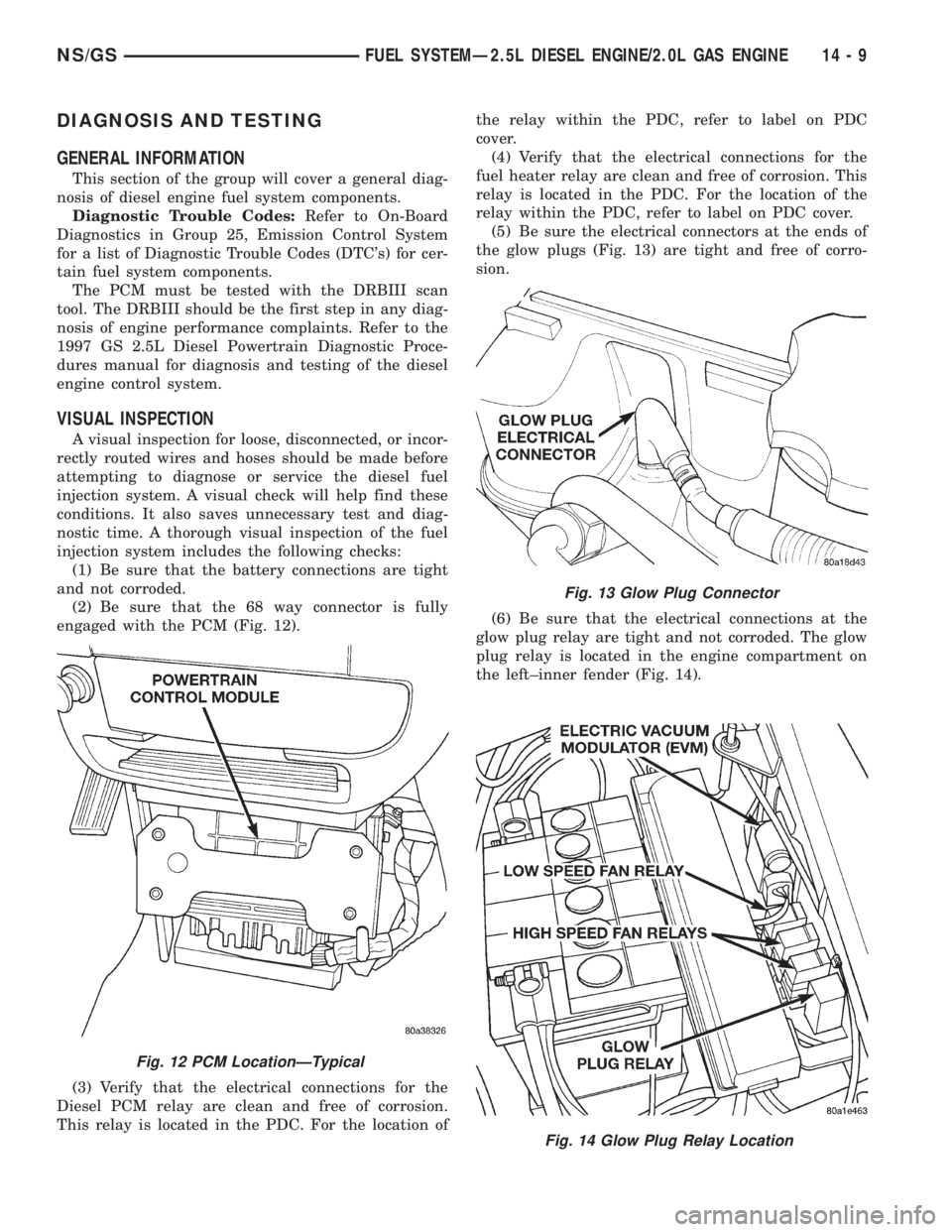
(2) Be sure that the 68 way connector is fully
engaged with the PCM (Fig. 12).
(3) Verify that the electrical connections for the
Diesel PCM relay are clean and free of corrosion.
This relay is located in the PDC. For the location ofthe relay within the PDC, refer to label on PDC
cover.
(4) Verify that the electrical connections for the
fuel heater relay are clean and free of corrosion. This
relay is located in the PDC. For the location of the
relay within the PDC, refer to label on PDC cover.
(5) Be sure the electrical connectors at the ends of
the glow plugs (Fig. 13) are tight and free of corro-
sion.
(6) Be sure that the electrical connections at the
glow plug relay are tight and not corroded. The glow
plug relay is located in the engine compartment on
the left±inner fender (Fig. 14).
Fig. 12 PCM LocationÐTypical
Fig. 13 Glow Plug Connector
Fig. 14 Glow Plug Relay Location
NS/GSFUEL SYSTEMÐ2.5L DIESEL ENGINE/2.0L GAS ENGINE 14 - 9
Page 1381 of 1938
A defective fuel injection pump, defective fuel tim-
ing solenoid or misadjusted mechanical pump timing
can cause starting problems or prevent the engine
from revving up. It can also cause:
²Engine surge at idle
²Rough idle (warm engine)
²Low power
²Excessive fuel consumption
²Poor performance
²Low power
²Black smoke from the exhaust
²Blue or white fog like exhaust
²Incorrect idle or maximum speed
The electronically controlled fuel pump has no
mechanical governor like older mechanically con-
trolled fuel pumps. Do not remove the top cover of
the fuel pump, or the screws fastening the wiring
pigtail to the side of the pump.The warranty of
the injection pump and the engine may be void
if those seals have been removed or tampered
with.
FUEL SUPPLY RESTRICTIONS
LOW±PRESSURE LINES
Restricted or Plugged supply lines or fuel filter can
cause a timing fault that will cause the PCM to oper-
ate the engine in a ªLimp Homeº mode. See the
introduction of the Fuel Injection System in this
group for more information on the Limp Home mode.
Fuel supply line restrictions can cause starting prob-
lems and prevent the engine from revving up. The
starting problems include; low power and blue or
white fog like exhaust. Test all fuel supply lines for
restrictions or blockage. Flush or replace as neces-
sary. Bleed the fuel system of air once a fuel supply
line has been replaced. Refer to the Air Bleed Proce-
dure section of this group for procedures.
HIGH±PRESSURE LINES
Restricted (kinked or bent) high±pressure lines can
cause starting problems, poor engine performance
and black smoke from exhaust.
Examine all high±pressure lines for any damage.
Each radius on each high±pressure line must be
smooth and free of any bends or kinks.
Replace damaged, restricted or leaking high±pres-
sure fuel lines with the correct replacement line.
CAUTION: The high±pressure fuel lines must be
clamped securely in place in the holders. The lines
cannot contact each other or other components. Do
not attempt to weld high±pressure fuel lines or to
repair lines that are damaged. Only use the recom-
mended lines when replacement of high±pressure
fuel line is necessary.
FUEL SHUTDOWN SOLENOID TEST
Since diesel fuel injection does not use spark plugs
to start combustion, the only way to stop the engine
is to cut off the fuel supply. This is done with the
Fuel Shutdown Solenoid. If the engine cranks, but
refuses to start, it may be caused by a defective fuel
shutdown solenoid.
The fuel shutdown solenoid is not controlled
or operated by the PCM.Voltage to operate the
solenoid is supplied from the ignition (key) switch.
NOTE: Although the fuel shutdown solenoid is not
operated by the PCM, if the Fuel Shutdown Solenoid
has been disconnected, and the key turned on, the
PCM will sense that the solenoid is not in the circuit,
and will switch to a ªLimp Homeº mode. After recon-
necting the solenoid, the PCM will have to be reset
by clearing the codes with the DRBIII scan tool, or
disconnecting the vehicle's battery for several min-
utes. The DRBIII scan tool is the preferred method
for resetting the PCM. Refer to the 1998 GS 2.5L Die-
sel Powertrain Diagnostic Manual for procedure.
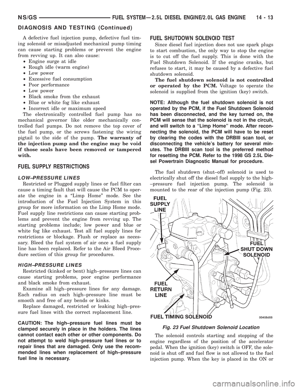
The fuel shutdown (shut±off) solenoid is used to
electrically shut off the diesel fuel supply to the high-
±pressure fuel injection pump. The solenoid is
mounted to the rear of the injection pump (Fig. 23).
The solenoid controls starting and stopping of the
engine regardless of the position of the accelerator
pedal. When the ignition (key) switch is OFF, the sole-
noid is shut off and fuel flow is not allowed to the fuel
injection pump. When the key is placed in the ON or
Fig. 23 Fuel Shutdown Solenoid Location
NS/GSFUEL SYSTEMÐ2.5L DIESEL ENGINE/2.0L GAS ENGINE 14 - 13
DIAGNOSIS AND TESTING (Continued)
Page 1390 of 1938

(14) Gauge reading should be at 0.60 mm. If not,
the pump must be rotated for adjustment:
(a) Loosen the three injection pump mounting
nuts at the mounting flanges. These flanges are
equipped with slotted holes. The slotted holes are
used to rotate and position the injection pump for
fuel timing. Loosen the three nuts just enough to
rotate the pump.
(b) Rotate the pumpclockwise(as viewed from
front) until .60 mm is indicated on the dial indica-
tor gauge.
(c) Tighten the three pump mounting nuts to 30
N´m (22 ft. lbs.) torque.
(d) Recheck the dial indicator after tightening
the pump mounting nuts. Gauge should still be
reading 0.60 mm. Loosen pump mounting nuts and
readjust if necessary.
(15) Remove dial indicator and adapter tools.
(16) Install access plug and washer to rear of
injection pump.
(17) Install plug at timing gear cover.
(18) Remove dial indicator from valve stem.
(19) Install valve spring and keepers.
(20) Install rocker arm assembly and tighten nuts.
(21) Install and connect the four high±pressure
fuel lines to the fuel injection pump. Also connect
fuel lines at the fuel injectors. For procedures, refer
to High±Pressure Fuel Lines in this group.
(22) Install electrical connector at engine coolant
temperature sensor.
(23) Connect electrical connector at fuel shutdown
solenoid.(24) Connect the main engine wiring harness to
the glow plugs.
(25) Connect the fuel timing solenoid pigtail har-
ness to the engine wiring harness.
(26) Connect the overflow valve/banjo fitting (fuel
return line assembly). Replace copper gaskets before
installing.
(27) Connect the rubber fuel return and supply
hoses to metal lines at pump. Tighten hose clamps to
2 N´m (20 in. lbs.) torque.
(28) Install generator assembly.
(29) Install engine accessory drive belt. Refer to
Group 7, Cooling System for procedures.
(30) Install negative battery cable to battery.
(31) Start the engine and bring to normal operat-
ing temperature.
(32) Check for fuel leaks.
FUEL INJECTORS
Four fuel injectors are used on each engine. Of these
four, two different types are used. The fuel injector used
on cylinder number one is equipped with a fuel injector
sensor (Fig. 47). The other three fuel injectors are iden-
tical.
Do not place the fuel injector equipped with
the fuel injector sensor into any other location
except the cylinder number one position.
REMOVAL
(1) Disconnect negative battery cable at battery.
(2) Thoroughly clean the area around the injector
with compressed air.
(3) Remove the fuel drain hoses (tubes) at each
injector (Fig. 48) being serviced. Each of these hoses
is slip±fit to the fitting on injector.
(4) Remove the high±pressure fuel line at injector
being removed. Refer to High±Pressure Fuel Lines in
this group for procedures.
(5) Remove the injector using special socket tool
number VM.1012A. When removing cylinder number
Fig. 46 Installing Dial Indicator and Special Adapter
Tools
Fig. 47 Fuel Injector SensorÐNumber±1 Cylinder
14 - 22 FUEL SYSTEMÐ2.5L DIESEL ENGINE/2.0L GAS ENGINENS/GS
REMOVAL AND INSTALLATION (Continued)
Page 1391 of 1938
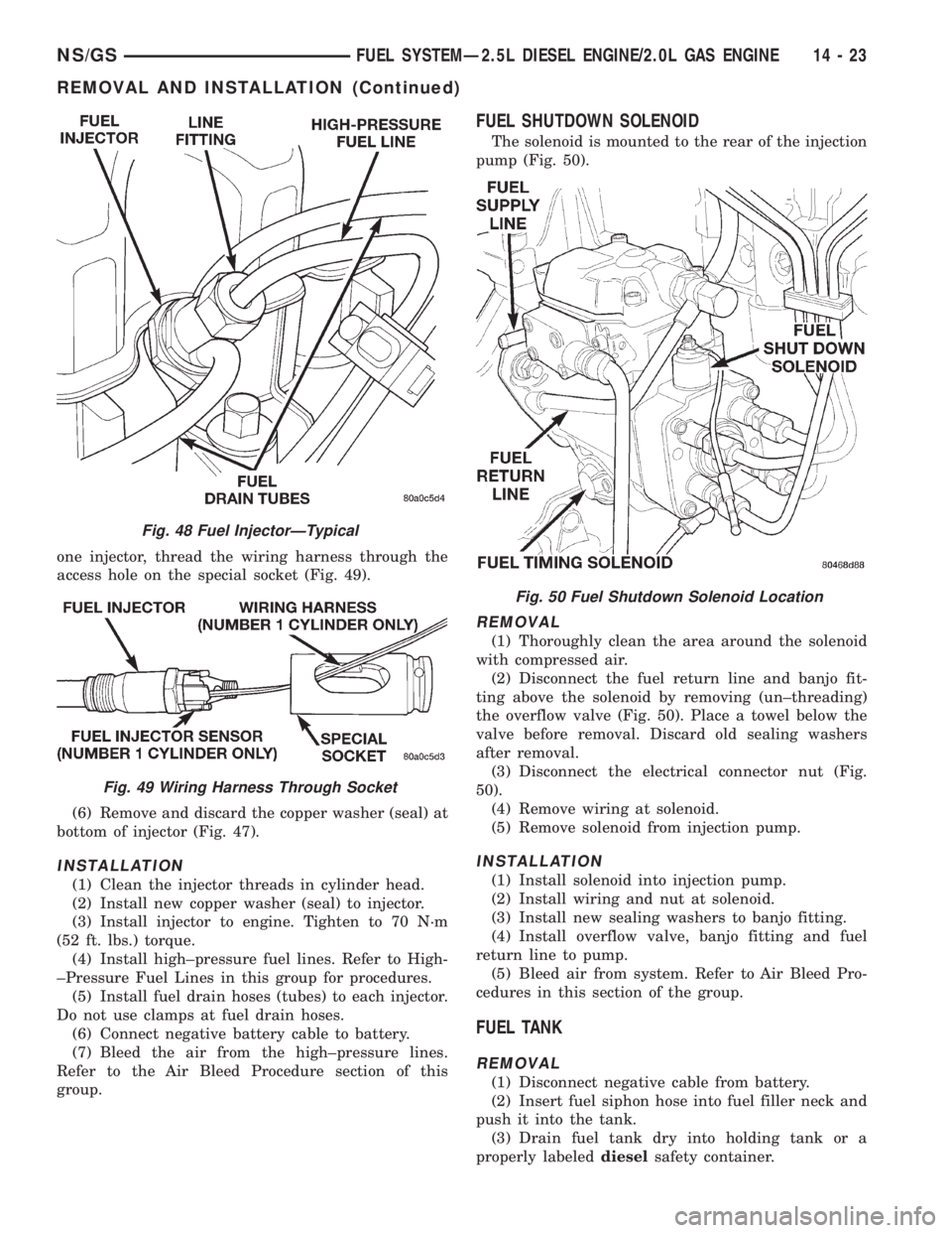
one injector, thread the wiring harness through the
access hole on the special socket (Fig. 49).
(6) Remove and discard the copper washer (seal) at
bottom of injector (Fig. 47).
INSTALLATION
(1) Clean the injector threads in cylinder head.
(2) Install new copper washer (seal) to injector.
(3) Install injector to engine. Tighten to 70 N´m
(52 ft. lbs.) torque.
(4) Install high±pressure fuel lines. Refer to High-
±Pressure Fuel Lines in this group for procedures.
(5) Install fuel drain hoses (tubes) to each injector.
Do not use clamps at fuel drain hoses.
(6) Connect negative battery cable to battery.
(7) Bleed the air from the high±pressure lines.
Refer to the Air Bleed Procedure section of this
group.
FUEL SHUTDOWN SOLENOID
The solenoid is mounted to the rear of the injection
pump (Fig. 50).
REMOVAL
(1) Thoroughly clean the area around the solenoid
with compressed air.
(2) Disconnect the fuel return line and banjo fit-
ting above the solenoid by removing (un±threading)
the overflow valve (Fig. 50). Place a towel below the
valve before removal. Discard old sealing washers
after removal.
(3) Disconnect the electrical connector nut (Fig.
50).
(4) Remove wiring at solenoid.
(5) Remove solenoid from injection pump.
INSTALLATION
(1) Install solenoid into injection pump.
(2) Install wiring and nut at solenoid.
(3) Install new sealing washers to banjo fitting.
(4) Install overflow valve, banjo fitting and fuel
return line to pump.
(5) Bleed air from system. Refer to Air Bleed Pro-
cedures in this section of the group.
FUEL TANK
REMOVAL
(1) Disconnect negative cable from battery.
(2) Insert fuel siphon hose into fuel filler neck and
push it into the tank.
(3) Drain fuel tank dry into holding tank or a
properly labeleddieselsafety container.
Fig. 48 Fuel InjectorÐTypical
Fig. 49 Wiring Harness Through Socket
Fig. 50 Fuel Shutdown Solenoid Location
NS/GSFUEL SYSTEMÐ2.5L DIESEL ENGINE/2.0L GAS ENGINE 14 - 23
REMOVAL AND INSTALLATION (Continued)
Page 1404 of 1938
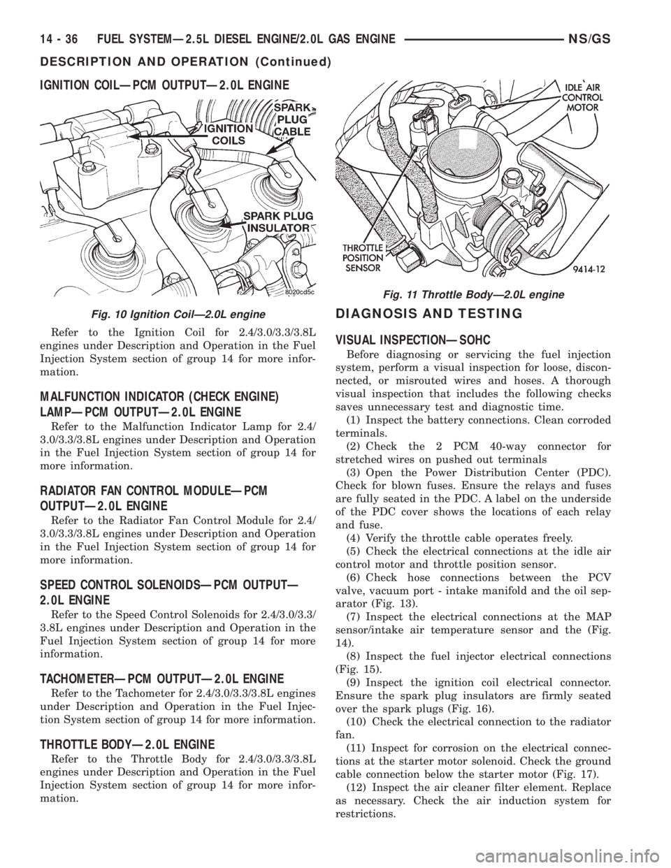
IGNITION COILÐPCM OUTPUTÐ2.0L ENGINE
Refer to the Ignition Coil for 2.4/3.0/3.3/3.8L
engines under Description and Operation in the Fuel
Injection System section of group 14 for more infor-
mation.
MALFUNCTION INDICATOR (CHECK ENGINE)
LAMPÐPCM OUTPUTÐ2.0L ENGINE
Refer to the Malfunction Indicator Lamp for 2.4/
3.0/3.3/3.8L engines under Description and Operation
in the Fuel Injection System section of group 14 for
more information.
RADIATOR FAN CONTROL MODULEÐPCM
OUTPUTÐ2.0L ENGINE
Refer to the Radiator Fan Control Module for 2.4/
3.0/3.3/3.8L engines under Description and Operation
in the Fuel Injection System section of group 14 for
more information.
SPEED CONTROL SOLENOIDSÐPCM OUTPUTÐ
2.0L ENGINE
Refer to the Speed Control Solenoids for 2.4/3.0/3.3/
3.8L engines under Description and Operation in the
Fuel Injection System section of group 14 for more
information.
TACHOMETERÐPCM OUTPUTÐ2.0L ENGINE
Refer to the Tachometer for 2.4/3.0/3.3/3.8L engines
under Description and Operation in the Fuel Injec-
tion System section of group 14 for more information.
THROTTLE BODYÐ2.0L ENGINE
Refer to the Throttle Body for 2.4/3.0/3.3/3.8L
engines under Description and Operation in the Fuel
Injection System section of group 14 for more infor-
mation.
DIAGNOSIS AND TESTING
VISUAL INSPECTIONÐSOHC
Before diagnosing or servicing the fuel injection
system, perform a visual inspection for loose, discon-
nected, or misrouted wires and hoses. A thorough
visual inspection that includes the following checks
saves unnecessary test and diagnostic time.
(1) Inspect the battery connections. Clean corroded
terminals.
(2) Check the 2 PCM 40-way connector for
stretched wires on pushed out terminals
(3) Open the Power Distribution Center (PDC).
Check for blown fuses. Ensure the relays and fuses
are fully seated in the PDC. A label on the underside
of the PDC cover shows the locations of each relay
and fuse.
(4) Verify the throttle cable operates freely.
(5) Check the electrical connections at the idle air
control motor and throttle position sensor.
(6) Check hose connections between the PCV
valve, vacuum port - intake manifold and the oil sep-
arator (Fig. 13).
(7) Inspect the electrical connections at the MAP
sensor/intake air temperature sensor and the (Fig.
14).
(8) Inspect the fuel injector electrical connections
(Fig. 15).
(9) Inspect the ignition coil electrical connector.
Ensure the spark plug insulators are firmly seated
over the spark plugs (Fig. 16).
(10) Check the electrical connection to the radiator
fan.
(11) Inspect for corrosion on the electrical connec-
tions at the starter motor solenoid. Check the ground
cable connection below the starter motor (Fig. 17).
(12) Inspect the air cleaner filter element. Replace
as necessary. Check the air induction system for
restrictions.
Fig. 10 Ignition CoilÐ2.0L engine
Fig. 11 Throttle BodyÐ2.0L engine
14 - 36 FUEL SYSTEMÐ2.5L DIESEL ENGINE/2.0L GAS ENGINENS/GS
DESCRIPTION AND OPERATION (Continued)
Page 1412 of 1938

illuminated constantly, it usually indicates a problem
has been detected somewhere within the fuel system.
The DRBIII scan tool is the best method for commu-
nicating with the PCM to diagnose faults within the
system.
DESCRIPTION AND OPERATION
POWERTRAIN CONTROL MODULE (PCM)
The Powertrain Control Module (PCM) is mounted
in the center consule to a bracket located in front of
the Air Bag Module (Fig. 1).
The PCM is a pre±programmed, dual micro±proces-
sor digital computer. It will either directly operate or
partially regulate the:
²Speed Control
²Speed Control LED lamp
²Fuel Timing Solenoid
²Glow Plug Relay
²Glow Plugs
²EGR Solenoid
²Glow Plug Lamp
²Diesel PCM Relay
²Air Conditioning Operation
²Tachometer
²Exhaust Gas Recirculation (EGR) Solenoid
The PCM can adapt its programming to meet
changing operating conditions.
The PCM receives input signals from various
switches and sensors. Based on these inputs, the
PCM regulates various engine and vehicle operationsthrough different system components. These compo-
nents are referred to asPCM Outputs.The sensors
and switches that provide inputs to the PCM are con-
sideredPCM Inputs.
PCM Inputs are:
²Air Conditioning Selection
²Theft Alarm
²Clutch Switch
²Diesel PCM Relay
²ISO-Protocol
²Control Sleeve
²Fuel Temperature
²Boost Pressure Sensor
²Accelerator Pedal Sensor
²EGR
²A/C Pressure
²Engine Coolant Temperature Sensor
²Low Idle Position Switch
²5 Volt Supply
²Vehicle Speed Sensor
²Sensor Return
²Glow Plug
²Engine Speed Sensor (rpm)
²Fuel Injector #1 Sensor
²Starter Signal
²Brake Switch
²Speed Control Switch Position
²Power Ground
²Signal Ground
²Ignition (key) Switch Sense
²Battery Voltage
²SCI Receive (DRB scan tool connection)
PCM Outputs:
After inputs are received by the PCM, certain sen-
sors, switches and components are controlled or reg-
ulated by the PCM. These are consideredPCM
Outputs.These outputs are for:
²A/C Clutch Relay (for A/C clutch operation)
²Speed Control LED
²Data Link Connectors (for DRB scan tool)
²Diesel PCM Relay
²Diesel PCM Sense
²Accelarator Pedal
²5 Volts Supply
²Glow Plug Relay
²Fan Relay
²Fuel Quantity
²Fuel Timing Solenoid
²Fuel Shut-Off Solenoid
²Engine Speed Sensor
²Glow Plug Lamp (malfunction indicator lamp)
²Exhaust Gas Recirculation (EGR) Solenoid
²Glow Plug Relay
²Tachometer
²SCI transmit (DRB scan tool connection)
Fig. 1 PCM Location
14 - 44 FUEL SYSTEMÐ2.5L DIESEL ENGINE/2.0L GAS ENGINENS/GS
GENERAL INFORMATION (Continued)
Page 1413 of 1938

BOOST PRESSURE SENSOR
The Boost Pressure Sensor is mounted to the top of
the intake manifold. (Fig. 2) It is a sensor that mea-
sures both manifold vacuum and turbo boost, and it
also contains an integrated intake air temperature
sensor. The Boost Pressure Sensor takes the place of
the Mass Air Flow (MAF). In the Intake Air Temper-
ature Sensor component, there is a ceramic element
that changes its resistance based on temperature.
The ceramic element is part of an electronic circuit
connected to the PCM, and has a voltage applied to
it. The ceramic element is exposed to the air inside
the intake. This air has a cooling effect on the
ceramic element, and its resistance changes. This
causes the voltage flowing through the intake air
temperature circuit to vary. The voltage signal pro-
duced by the Intake Air Temperature Sensor changes
inversely to the temperature, and is measured by the
PCM. As a general rule, when the temperature of the
air in the intake is high, the voltage signal produced
by the Intake Air Temperature Sensor is low. The
component of the Boost Pressure Sensor that mea-
sures manifold vacuum and turbo boost produces a
voltage signal that is proportional to the pressure in
the inake manifold. When the intake manifold pres-
sure is low, the voltage is low, and when the pressure
is high, the voltage is high. The PCM uses the volt-
age signals from the Boost Pressure Sensor, and the
Intake Air Temperature Sensor to determine the
amount of air flowing through the intake manifold.
VEHICLE THEFT ALARM
The PCM can learn if the vehicle has a Vehicle
Theft Alarm (VTA) system. Once it detects the vehi-
cle having VTA,the controller can ONLY BE
USED ON VEHICLES WITH VTA.If the PCM is put it on a vehicle without VTA the
Glow Plug Lamp will start to blink and the vehicle
will not start.
The PCM cannot be flashed to remove the VTA.
BATTERY VOLTAGEÐPCM INPUT
The battery voltage input provides power to the
PCM. It also informs the PCM what voltage level is
being supplied by the generator once the vehicle is
running.
The battery input also provides the voltage that is
needed to keep the PCM memory alive. The memory
stores Diagnostic Trouble Code (DTC) messages.
Trouble codes will still be stored even if the battary
voltage is lost.
SENSOR RETURNÐPCM INPUT (ANALOG
GROUND)
Sensor Return provides a low noise Analog ground
reference for all system sensors.
SIGNAL GROUNDÐPCM INPUT
Signal ground provides a low noise ground to the
data link connector.
IGNITION CIRCUIT SENSEÐPCM INPUT
The ignition circuit sense input signals the PCM
that the ignition (key) switch has been turned to the
ON position. This signal initiates the glow plug con-
trol routine to begin the ªpre±heatº cycle.
START SIGNALÐPCM INPUT
This input tells the PCM that the engine starter is
being operated. This in turn will start the glow plug
ªpost±heatº cycle.
POWER GROUND
Provides a common ground for power devices (sole-
noid and relay devices).
NEEDLE MOVEMENT OR INSTRUMENTED FIRST
INJECTORÐPCM INPUT
This input from the PCM supplies a constant 30
mA electrical current source for the first injector sen-
sor. It will vary the voltage to this sensor when it
senses a mechanical movement within the injector
needle (pintle) of the number±1 cylinder fuel injector.
When this voltage has been determined by the PCM,
it will then control an output to the fuel timing sole-
noid (the fuel timing solenoid is located on the fuel
injection pump). Also refer to Fuel Injection Pump for
additional information.
The first injector sensor is a magnetic (inductive)
type.
Fig. 2 Boost Pressure Sensor Location
NS/GSFUEL SYSTEMÐ2.5L DIESEL ENGINE/2.0L GAS ENGINE 14 - 45
DESCRIPTION AND OPERATION (Continued)
Page 1416 of 1938
The speed sensor generates 8 pulses per sensor
revolution. These signals, in conjunction with a
closed throttle signal from the throttle position sen-
sor, indicate a closed throttle deceleration to the
PCM. When the vehicle is stopped at idle, a closed
throttle signal is received by the PCM (but a speed
sensor signal is not received).
In addition to determining distance and vehicle
speed, the output from the sensor is used to control
speed control operation.
SPEED CONTROLÐPCM INPUTS
The speed control system provides five separate
inputs to the PCM; On/Off, Set, Resume/Accel, Cancel,
and Decel.. The On/Off input informs the PCM that
the speed control system has been activated. The Set
input informs the PCM that a fixed vehicle speed has
been selected. The Resume input indicates to the PCM
that the previous fixed speed is requested.
Speed control operation will start at 50 km/h±142
km/h (35±85 mph). The upper range of operation is
not restricted by vehicle speed. Inputs that affect
speed control operation are vehicle speed sensor and
throttle position sensor.
Refer to Group 8H for further speed control infor-
mation.
DIESEL PCM RELAYÐPCM INPUT
A 12 volt signal at this input indicates to the PCM
that the Diesel relay has been activated. The Diesel
relay is located in the PDC. The PDC is located next
to the battery in the engine compartment. For the
location of the relay within the PDC, refer to label on
PDC cover.
This input is used only to sense that the Diesel
relay is energized. If the PCM does not see 12 volts +
at this input when the Diesel relay should be acti-
vated, it will set a Diagnostic Trouble Code (DTC).
FIVE VOLT POWERÐPCM OUTPUT
This circuit supplies approximately 5 volts to
power the Accelerator Pedal Postion Sensor, Mass Air
Flow Sensor, and A/C Pressure Sensor.
ENGINE COOLANT GAUGEÐPCM OUTPUT
Refer to the Instrument Panel and Gauges group
for additional information.
ENGINE OIL PRESSURE GAUGEÐPCM OUTPUT
Refer to the Instrument Panel and Gauges group
for additional information.
GLOW PLUG LAMPÐPCM OUTPUT
The Glow Plug lamp (malfunction indicator lamp)
illuminates on the message center each time the igni-
tion (key) switch is turned on. It will stay on for
about two seconds as a bulb test.If the PCM receives an incorrect signal, or no sig-
nal from certain sensors or components, the lamp
BLINKS. This is a warning that the PCM has
recorded a system or sensor malfunction. It signals
an immediate need for service. There are only 5
HARD faults that can turn on this lamp to make it
blink.
SPEED CONTROLÐPCM OUTPUTS
These two circuits control the fuel quantity actua-
tor to regulate vehicle speed. Refer to Group 8H for
Speed Control information.
AIR CONDITIONING RELAYÐPCM OUTPUT
This circuit controls a ground signal for operation
of the A/C clutch relay. Also refer to Air Conditioning
(A/C) ControlsÐPCM Input for additional informa-
tion.
The A/C relay is located in the Power Distribution
Center (PDC). The PDC is located next to the battery
in the engine compartment. For the location of the
relay within the PDC, refer to label on PDC cover.
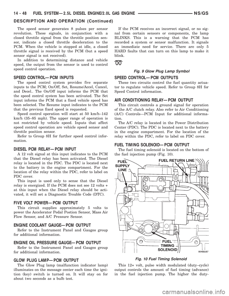
FUEL TIMING SOLENOIDÐPCM OUTPUT
The fuel timing solenoid is located on the bottom of
the fuel injection pump (Fig. 10).
This 12+ volt, pulse width modulated (duty±cycle)
output controls the amount of fuel timing (advance)
in the fuel injection pump. The higher the duty-
Fig. 9 Glow Plug Lamp Symbol
Fig. 10 Fuel Timing Solenoid
14 - 48 FUEL SYSTEMÐ2.5L DIESEL ENGINE/2.0L GAS ENGINENS/GS
DESCRIPTION AND OPERATION (Continued)
Page 1420 of 1938

In this chart, Pre±Heat and Post±Heat times are
mentioned. Pre±heat is the amount of time the glow
plug relay circuit is activated when the ignition (key)
switch is ON, but the engine has yet to be started.
Post±heat is the amount of time the glow plug relay
circuit is activated after the engine is operating. The
Glow Plug lamp will not be illuminated during the
post±heat cycle.
TESTING:
Disconnect and isolate the electrical connectors
(Fig. 16) at all four glow plugs. With the engine cool
or cold, and the key in the ON position, check for
10±12 volts + at each electrical connector. 10±12 volts
+ should be at each connector whenever the PCM is
operating in the pre±heat or post±heat cycles (refer
to the following Glow Plug Control chart).Be very
careful not to allow any of the four discon-
nected glow plug electrical connectors to con-
tact a metal surface. When the key is turned to
the ON position, approximately 100 amps at 12
volts is supplied to these connectors.If 10±12
volts + is not available at each connector, check con-
tinuity of wiring harness directly to the relay. If con-
tinuity is good directly to the relay, the fault is either
with the relay or the relay input from the PCM. To
test the relay only, refer to RelaysÐOperation/Test-
ing in this section of the group. If the relay test is
good, refer to the DRB scan tool.
Diagnostic Trouble Codes:Refer to On-Board
Diagnostics in Group 25, Emission Control System
for a list of Diagnostic Trouble Codes (DTC's) for cer-
tain fuel system components.
RELAYSÐOPERATION/TESTING
The following description of operation and
tests apply only to the Diesel PCM and other
relays. The terminals on the bottom of each relay
are numbered (Fig. 17).
OPERATION
²Terminal number 30 is connected to battery volt-
age. For both the Diesel and other relays, terminal
30 is connected to battery voltage at all times.
²The PCM grounds the coil side of the relay
through terminal number 85.
²Terminal number 86 supplies voltage to the coil
side of the relay.
²When the PCM de-energizes the Diesel PCM
and other relays, terminal number 87A connects to
terminal 30. This is the Off position. In the off posi-
tion, voltage is not supplied to the rest of the circuit.
Terminal 87A is the center terminal on the relay.
Fig. 15 Glow Plug Relay Location
Fig. 16 Wiring Connection at Glow Plug
GLOW PLUG CONTROL
14 - 52 FUEL SYSTEMÐ2.5L DIESEL ENGINE/2.0L GAS ENGINENS/GS
DIAGNOSIS AND TESTING (Continued)
Page 1422 of 1938

(2) Remove the sensor mounting bolts.
(3) Remove the sensor.
INSTALLATION
(1) Install the sensor flush against the opening in
the transmission housing.
(2) Install and tighten the sensor mounting bolt to
19 N´m (14 ft. lbs.) torque.
(3) Connect the electrical connector to the sensor.
ENGINE COOLANT TEMPERATURE SENSOR
The sensor is located on the side of cylinder head
near the rear of fuel injection pump (Fig. 19).
REMOVAL
WARNING: HOT, PRESSURIZED COOLANT CAN
CAUSE INJURY BY SCALDING. COOLING SYSTEM
MUST BE PARTIALLY DRAINED BEFORE REMOV-
ING THE COOLANT TEMPERATURE SENSOR.
REFER TO GROUP 7, COOLING.
(1) Partially drain cooling system. Refer to Group
7, Cooling.
(2) Disconnect electrical connector from sensor.
(3) Remove sensor from cylinder head.
INSTALLATION
(1) Install a new copper gasket to sensor.
(2) Install sensor to cylinder head.
(3) Tighten sensor to 18 N´m (13 ft. lbs.) torque.
(4) Connect electrical connector to sensor.
(5) Replace any lost engine coolant. Refer to Group
7, Cooling System.
GLOW PLUGS
The glow plugs are located above each fuel injector
(Fig. 20). Four individual plugs are used.
REMOVAL
(1) Disconnect the negative battery cable at the
battery.
(2) Clean the area around the glow plug with com-
pressed air before removal.
(3) Disconnect electrical connector (Fig. 21) at glow
plug.
(4) Remove the glow plug (Fig. 20) from cylinder
head.
Fig. 18 Engine Speed SensorFig. 19 Engine Coolant Temperature Sensor
Location
Fig. 20 Glow Plug
14 - 54 FUEL SYSTEMÐ2.5L DIESEL ENGINE/2.0L GAS ENGINENS/GS
REMOVAL AND INSTALLATION (Continued)