brake fluid CHRYSLER VOYAGER 1996 Repair Manual
[x] Cancel search | Manufacturer: CHRYSLER, Model Year: 1996, Model line: VOYAGER, Model: CHRYSLER VOYAGER 1996Pages: 1938, PDF Size: 55.84 MB
Page 477 of 1938
BULB APPLICATION
INDEX
page page
GENERAL INFORMATION
INTRODUCTION......................... 25SPECIFICATIONS
EXTERIOR LAMP BULBS.................. 25
INTERIOR LAMP BULBS.................. 25
GENERAL INFORMATION
INTRODUCTION
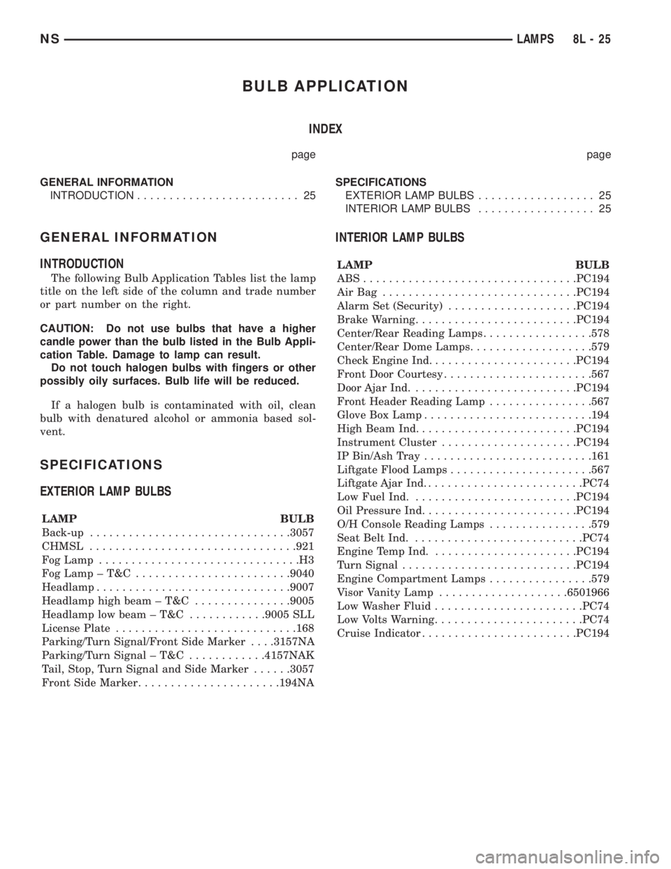
The following Bulb Application Tables list the lamp
title on the left side of the column and trade number
or part number on the right.
CAUTION: Do not use bulbs that have a higher
candle power than the bulb listed in the Bulb Appli-
cation Table. Damage to lamp can result.
Do not touch halogen bulbs with fingers or other
possibly oily surfaces. Bulb life will be reduced.
If a halogen bulb is contaminated with oil, clean
bulb with denatured alcohol or ammonia based sol-
vent.
SPECIFICATIONS
EXTERIOR LAMP BULBS
LAMP BULB
Back-up...............................3057
CHMSL................................921
Fog Lamp...............................H3
FogLamp±T&C ........................9040
Headlamp..............................9007
Headlamp high beam ± T&C...............9005
Headlamp low beam ± T&C............9005 SLL
License Plate............................168
Parking/Turn Signal/Front Side Marker. . . .3157NA
Parking/Turn Signal ± T&C............4157NAK
Tail, Stop, Turn Signal and Side Marker......3057
Front Side Marker......................194NA
INTERIOR LAMP BULBS
LAMP BULB
ABS.................................PC194
AirBag ..............................PC194
Alarm Set (Security)....................PC194
Brake Warning.........................PC194
Center/Rear Reading Lamps.................578
Center/Rear Dome Lamps...................579
Check Engine Ind.......................PC194
Front Door Courtesy.......................567
Door Ajar Ind..........................PC194
Front Header Reading Lamp................567
Glove Box Lamp..........................194
High Beam Ind.........................PC194
Instrument Cluster.....................PC194
IP Bin/Ash Tray..........................161
Liftgate Flood Lamps......................567
Liftgate Ajar Ind.........................PC74
Low Fuel Ind..........................PC194
Oil Pressure Ind........................PC194
O/H Console Reading Lamps................579
Seat Belt Ind...........................PC74
Engine Temp Ind.......................PC194
Turn Signal...........................PC194
Engine Compartment Lamps................579
Visor Vanity Lamp....................6501966
Low Washer Fluid.......................PC74
Low Volts Warning.......................PC74
Cruise Indicator........................PC194
NSLAMPS 8L - 25
Page 495 of 1938
BULB APPLICATION
INDEX
page page
GENERAL INFORMATION
INTRODUCTION....................... 17
CLEANING AND INSPECTION
HEADLAMP CLEANING.................. 17SPECIFICATIONS
EXTERIOR LAMP BULBS................. 17
INTERIOR LAMP BULBS................. 17
GENERAL INFORMATION
INTRODUCTION
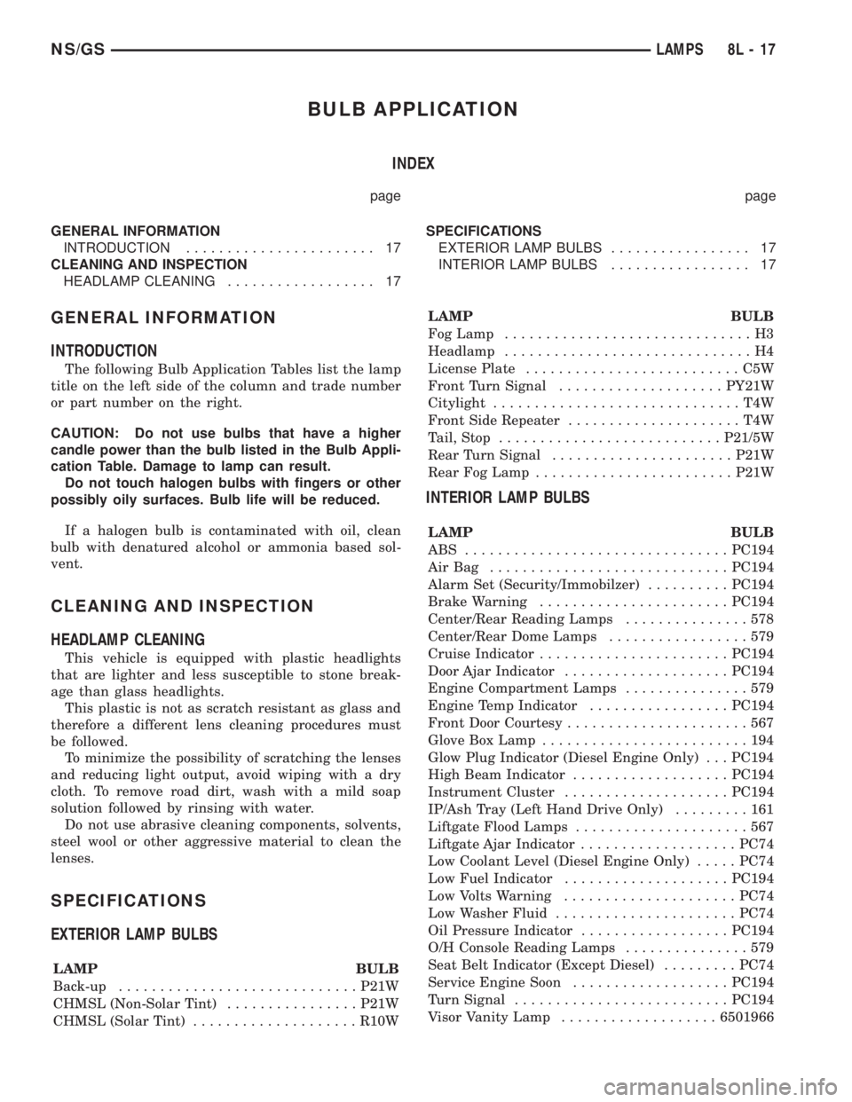
The following Bulb Application Tables list the lamp
title on the left side of the column and trade number
or part number on the right.
CAUTION: Do not use bulbs that have a higher
candle power than the bulb listed in the Bulb Appli-
cation Table. Damage to lamp can result.
Do not touch halogen bulbs with fingers or other
possibly oily surfaces. Bulb life will be reduced.
If a halogen bulb is contaminated with oil, clean
bulb with denatured alcohol or ammonia based sol-
vent.
CLEANING AND INSPECTION
HEADLAMP CLEANING
This vehicle is equipped with plastic headlights
that are lighter and less susceptible to stone break-
age than glass headlights.
This plastic is not as scratch resistant as glass and
therefore a different lens cleaning procedures must
be followed.
To minimize the possibility of scratching the lenses
and reducing light output, avoid wiping with a dry
cloth. To remove road dirt, wash with a mild soap
solution followed by rinsing with water.
Do not use abrasive cleaning components, solvents,
steel wool or other aggressive material to clean the
lenses.
SPECIFICATIONS
EXTERIOR LAMP BULBS
LAMP BULB
Back-up.............................P21W
CHMSL (Non-Solar Tint)................P21W
CHMSL (Solar Tint)....................R10WLAMP BULB
Fog Lamp..............................H3
Headlamp..............................H4
License Plate..........................C5W
Front Turn Signal....................PY21W
Citylight..............................T4W
Front Side Repeater.....................T4W
Tail, Stop...........................P21/5W
Rear Turn Signal......................P21W
Rear Fog Lamp........................P21W
INTERIOR LAMP BULBS
LAMP BULB
ABS ................................PC194
AirBag .............................PC194
Alarm Set (Security/Immobilzer)..........PC194
Brake Warning.......................PC194
Center/Rear Reading Lamps...............578
Center/Rear Dome Lamps.................579
Cruise Indicator.......................PC194
Door Ajar Indicator....................PC194
Engine Compartment Lamps...............579
Engine Temp Indicator.................PC194
Front Door Courtesy......................567
Glove Box Lamp.........................194
Glow Plug Indicator (Diesel Engine Only) . . . PC194
High Beam Indicator...................PC194
Instrument Cluster....................PC194
IP/Ash Tray (Left Hand Drive Only).........161
Liftgate Flood Lamps.....................567
Liftgate Ajar Indicator...................PC74
Low Coolant Level (Diesel Engine Only).....PC74
Low Fuel Indicator....................PC194
Low Volts Warning.....................PC74
Low Washer Fluid......................PC74
Oil Pressure Indicator..................PC194
O/H Console Reading Lamps...............579
Seat Belt Indicator (Except Diesel).........PC74
Service Engine Soon...................PC194
Turn Signal..........................PC194
Visor Vanity Lamp...................6501966
NS/GSLAMPS 8L - 17
Page 578 of 1938

Component Page
Fuel Tank Module...................8W-30, 45
Fuel Temperature Sensor.................8W-30
Fuel Timing Solenoid....................8W-30
Fuses (JB)............................8W-12
Fuses (PDC)...........................8W-10
Fusible Link.....................8W-20, 21, 63
Fusible Link A0........................8W-30
Fusible Link A11.......................8W-10
Fusible Link A54.......................8W-10
Grounds..............................8W-15
Generator.............................8W-20
Glove Box Lamp........................8W-44
Glow Plug Lamp.....................8W-30, 46
Glow Plugs............................8W-30
Glow Plug Relay........................8W-30
Headlamps............................8W-50
Headlamp Dimmer Switch..........8W-10, 46, 50
Headlamp Leveling Motors...............8W-50
Headlamp Switch.......................8W-50
Headlamp Washer......................8W-53
High Beam Indicator....................8W-46
High Beam Relay....................8W-10, 50
Headlamps............................8W-50
Horns................................8W-41
Hood Ajar Switch....................8W-39, 44
Horn Relay.........................8W-39, 41
Horn Switch.....................8W-10, 39, 41
HVAC Control.........................8W-42
Idle Air Control Motor...................8W-30
Ignition Coil Pack.......................8W-30
Ignition Switch.........................8W-10
Instrument Cluster.....................8W-40
Intake Air Temperature Sensor............8W-30
Intake Air Temperature/Manifold Absolute
Pressure Sensor.....................8W-30
Interior Lamps On Switch................8W-44
Junction Block.........................8W-12
Key-In Halo Lamp......................8W-44
Knock Sensor..........................8W-30
Lamp Assemblies.......................8W-51
License Lamp..........................8W-51
Liftgate Ajar Indicator Lamp..............8W-40
Liftgate Ajar Switch...............8W-39, 40, 44
Liftgate Arm/Disarm Switch............8W-39, 61
Liftgate Flood Lamps....................8W-44
Liftgate Lock Motor.....................8W-61
Low Beam Relay.....................8W-10, 50
Low Coolant Level Switch................8W-45
Low Fuel Warning Indicator Lamp..........8W-40
Low Oil Pressure Lamp..................8W-46
Low Washer Fluid Level Indicator Lamp.....8W-40
Low Washer Fluid Switch.................8W-53
Low/Reverse Pressure Switch..............8W-31
Low/Reverse Solenoid....................8W-31Component Page
Manifold Absolute Pressure Sensor.........8W-30
Memory Power Seat Switch...............8W-63
Seat Sensors...........................8W-63
Memory Seat/Mirror Module...........8W-62, 63
Memory Set Switch..................8W-62, 63
Message Center........................8W-46
Mid Reading Lamps.....................8W-44
Mode Door Actuator.....................8W-42
Name Brand Speaker Relay...............8W-47
Needle Movement Sensor.................8W-30
Odometer.............................8W-40
Output Shaft Speed Sensor...............8W-31
Overdrive Pressure Switch................8W-31
Overdrive Solenoid......................8W-31
Overhead Console.......................8W-49
Park Brake Switch...................8W-46, 50
Park Lamp Relay.........8W-10, 12, 44, 50, 51, 54
Park/Turn Signal Lamps.................8W-50
Airbag Squibs..........................8W-43
Power Distribution Center................8W-10
Power Folding Mirror Switch..............8W-62
Power Mirror Fold Relay.................8W-62
Power Mirror Switch....................8W-62
Power Mirror Unfold Relay...............8W-62
Power Seat Circuit Breaker............8W-62, 63
Powertrain Control Module...............8W-30
PTCs (JB).............................8W-12
Radiator Fan Disconnect.................8W-42
Radiator Fan Relays.....................8W-42
Radio................................8W-47
Radio Choke...........................8W-47
Reading Lamps........................8W-44
Rear A/C Heater Unit....................8W-42
Rear Blower Control Switches.............8W-42
Rear Cigar Lighter/Power Outlet...........8W-41
Rear Defogger On Indicator...............8W-42
Rear Dome Lamp.......................8W-44
Rear Fog Lamp.........................8W-51
Rear Fog Lamp Indicator.................8W-51
Rear Washer Motor.....................8W-53
Rear Washer Switch..................8W-42, 53
Rear Window Defogger...................8W-48
Rear Window Defogger Relay..............8W-48
Rear Window Defogger Switch..........8W-42, 48
Rear Wiper Delay On Indicator.........8W-42, 53
Rear Wiper Delay Switch..............8W-42, 53
Rear Wiper Motor.......................8W-53
Rear Wiper On Indicator..............8W-42, 53
Rear Wiper On Switch................8W-42, 53
Recirculate Mode Indicator................8W-42
Recirculate Mode Switch.................8W-42
Recirculation Door Actuator...............8W-42
Remote Keyless Entry Module.............8W-61
Repeater Lamps.....................8W-51, 52
8W - 02 - 2 8W - 02 COMPONENT INDEXNS/GS
Page 643 of 1938
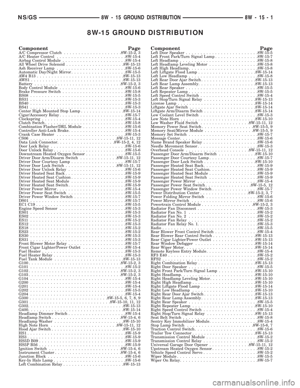
8W-15 GROUND DISTRIBUTION
Component PageA/C Compressor Clutch....................8W-15-2, 3
A/C Heater Control........................8W-15-4
Airbag Control Module......................8W-15-4
All Wheel Drive Solenoid....................8W-15-13
Ash Receiver Lamp........................8W-15-6
Automatic Day/Night Mirror...................8W-15-5
AW4B13..............................8W-15-13
AWS1................................8W-15-13
Battery..............................8W-15-2, 3
Body Control Module.......................8W-15-6
Brake Pressure Switch......................8W-15-8
BS08.................................8W-15-5
BS31.................................8W-15-3
BS40.................................8W-15-3
BS41.................................8W-15-3
Center High Mounted Stop Lamp...............8W-15-14
Cigar/Accessory Relay.......................8W-15-7
Clockspring.............................8W-15-4
Clutch Switch............................8W-15-8
Combination Flasher/DRL Module...............8W-15-6
Controller Anti-Lock Brake....................8W-15-4
Crank Case Heater........................8W-15-3
CS06..............................8W-15-11, 12
Data Link Connector....................8W-15-2, 4, 12
Door Lock Relay..........................8W-15-6
Door Unlock Relay.........................8W-15-6
Downstream Heated Oxygen Sensor..............8W-15-5
Driver Door Arm/Disarm Switch.............8W-15-11, 12
Driver Door Courtesy Lamp...................8W-15-7
Driver Door Lock Switch..................8W-15-11, 12
Driver Door Unlock Relay....................8W-15-6
Driver Heated Seat Back.....................8W-15-9
Driver Heated Seat Cushion...................8W-15-9
Driver Heated Seat Module...................8W-15-9
Driver Heated Seat Switch....................8W-15-9
Driver Power Mirror........................8W-15-4
Driver Power Seat Switch....................8W-15-5
Driver Power Window Switch..................8W-15-7
DS01.................................8W-15-7
EC1C19...............................8W-15-5
Engine Speed Sensor.......................8W-15-3
ES01.................................8W-15-3
ES02.................................8W-15-3
ES11 .................................8W-15-2
ES12.................................8W-15-3
ES18.................................8W-15-2
ES23.................................8W-15-2
ES30.................................8W-15-3
ES31.................................8W-15-3
Front Blower Motor Relay....................8W-15-7
Front Cigar Lighter/Power Outlet...............8W-15-4
Fuel Heater.............................8W-15-3
Fuel Heater Relay.........................8W-15-3
Fuel Tank Module........................8W-15-13
G100................................8W-15-2, 3
G101.................................8W-15-2
G102................................8W-15-2, 3
G103................................8W-15-2, 3
G104.................................8W-15-4
G200.................................8W-15-4
G201.................................8W-15-4
G202.................................8W-15-5
G204.................................8W-15-4
G300...........................8W-15-5, 6, 7, 8, 9
G301............................8W-15-10, 11, 12
G302.................................8W-15-13
G400.................................8W-15-14
Headlamp Dimmer Switch....................8W-15-4
Headlamp Switch........................8W-15-4, 6
Headlamp Washer........................8W-15-10
High Note Horn.......................8W-15-11, 12
Hood Ajar Switch.........................8W-15-10
HS1..................................8W-15-9
HS3..................................8W-15-9
HS5D B09..............................8W-15-9
HS5P B56..............................8W-15-9
Ignition Switch.........................8W-15-4, 6
Instrument Cluster.......................8W-15-4, 6
Junction Block...........................8W-15-6
Key-In Halo Lamp.........................8W-15-6
Left Combination Relay.....................8W-15-13Component PageLeft Door Speaker.........................8W-15-5
Left Front Park/Turn Signal Lamp...............8W-15-7
Left Headlamp...........................8W-15-8
Left Headlamp Leveling Motor.................8W-15-8
Left High Headlamp........................8W-15-8
Left Liftgate Flood Lamp....................8W-15-14
Left Low Headlamp........................8W-15-8
Left Rear Door Ajar Switch...................8W-15-13
Left Rear Lamp Assembly....................8W-15-13
Left Rear Speaker.........................8W-15-5
Left Repeater Lamp........................8W-15-5
Left Speed Control Switch....................8W-15-4
Left Stop/Turn Signal Relay..................8W-15-13
License Lamp...........................8W-15-14
Liftgate Ajar Switch.......................8W-15-14
Liftgate Arm/Disarm Switch..................8W-15-14
Low Coolant Level Switch....................8W-15-3
Low Note Horn..........................8W-15-10
Low Washer Fluid Switch.................8W-15-11, 12
Memory Power Seat Switch..................8W-15-5, 9
Memory Seat/Mirror Module.................8W-15-5, 9
Memory Set Switch........................8W-15-7
Message Center...........................8W-15-6
Name Brand Speaker Relay...................8W-15-6
Needle Movement Sensor.....................8W-15-3
Overhead Console......................8W-15-11, 12
Passenger Door Arm/Disarm Switch.............8W-15-10
Passenger Door Courtesy Lamp.................8W-15-7
Passenger Door Lock Switch..................8W-15-10
Passenger Heated Seat Back...................8W-15-9
Passenger Heated Seat Cushion.................8W-15-9
Passenger Heated Seat Module.................8W-15-9
Passenger Heated Seat Switch.................8W-15-9
Passenger Power Mirror.....................8W-15-4
Passenger Power Seat Switch................8W-15-5, 12
Passenger Power Window Switch................8W-15-7
Power Distribution Center.................8W-15-2, 3, 7
Power Folding Mirror Switch..................8W-15-6
Power Mirror Switch.......................8W-15-6
Powertrain Control Module..................8W-15-2, 3
Radiator Fan Disconnect.....................8W-15-3
Radiator Fan No. 1........................8W-15-2
Radiator Fan No. 2........................8W-15-2
Radiator Fan Relay........................8W-15-2
Radiator Fan Relay No. 1.....................8W-15-3
Radio.................................8W-15-5
Rear Blower Front Control Switch...............8W-15-4
Rear Blower Rear Control Switch...............8W-15-13
Rear Cigar Lighter/Power Outlet...............8W-15-13
Rear Window Defogger.....................8W-15-14
Rear Wiper Motor.........................8W-15-14
Remote Keyless Entry Module..................8W-15-4
RF3E40...............................8W-15-2
RFS2.................................8W-15-2
Right Combination Relay....................8W-15-13
Right Door Speaker........................8W-15-5
Right Front Park/Turn Signal Lamp.............8W-15-10
Right Headlamp..........................8W-15-10
Right Headlamp Leveling Motor................8W-15-10
Right High Headlamp......................8W-15-10
Right Liftgate Flood Lamp...................8W-15-14
Right Low Headlamp......................8W-15-10
Right Rear Door Ajar Switch..................8W-15-13
Right Rear Lamp Assembly...................8W-15-13
Right Rear Speaker........................8W-15-5
Right Repeater Lamp......................8W-15-10
Right Speed Control Switch...................8W-15-4
Right Stop/Turn Signal Relay.................8W-15-13
Seat Belt Switch..........................8W-15-8
Sentry Key Immobilizer Module.................8W-15-4
Stop Lamp Switch.......................8W-15-6, 7
Traction Control Switch......................8W-15-6
Trailer Tow Connector......................8W-15-13
Transmission Control Module..................8W-15-2
Transmission Control Relay...................8W-15-2
Universal Garage Door Opener..............8W-15-11, 12
Upstream Heated Oxygen Sensor................8W-15-2
Vehicle Speed Control Servo...................8W-15-2
Wiper Module............................8W-15-5
Wiper On Relay...........................8W-15-7
NS/GS8W - 15 GROUND DISTRIBUTION 8W - 15 - 1
Page 769 of 1938

8W-45 BODY CONTROL MODULE
Component Page
A/C Heater Control..................8W-45-5, 6
Ash Receiver Lamp....................8W-45-5
Automatic Day/Night Mirror.............8W-45-8
Back-Up Switch.......................8W-45-9
Battery.............................8W-45-9
Body Control Module . .8W-45-2, 3, 4, 5, 6, 7, 8, 9, 10
BS02...............................8W-45-9
BS10...............................8W-45-8
BS30...............................8W-45-9
Clockspring..........................8W-45-3
Combination Flasher/DRL Module........8W-45-5
Controller Anti-Lock Brake..............8W-45-6
CS03...............................8W-45-8
Data Link Connector...................8W-45-3
Door Lock Relay......................8W-45-7
Door Unlock Relay....................8W-45-7
Driver Door Ajar Switch................8W-45-7
Driver Door Arm/Disarm Switch..........8W-45-8
Driver Door Lock Switch..............8W-45-6, 8
Driver Door Unlock Relay...............8W-45-7
Driver Power Mirror..................8W-45-10
Driver Power Window Switch............8W-45-6
Engine Coolant Temperature Sensor.......8W-45-9
Engine Oil Pressure Switch..............8W-45-7
ES01...............................8W-45-9
ES02...............................8W-45-9
Front Cigar Lighter/Power Outlet.........8W-45-5
Front Reading Lamps/Switch............8W-45-8
Front Wiper Switch....................8W-45-4
Fuel Tank Module...................8W-45-7, 9
Fuse 1 (JB)..........................8W-45-3
Fuse 2 (JB)..........................8W-45-2
Fuse 3 (JB)..........................8W-45-3
Fuse 6 (JB)..........................8W-45-2
Fuse 19 (PDC)........................8W-45-4
Fuse 22 (PDC)........................8W-45-3
Fuse 28 (PDC)........................8W-45-2
G100...............................8W-45-9
G103...............................8W-45-9
G300............................8W-45-2, 10
G302...............................8W-45-9
Glove Box Lamp......................8W-45-8
Headlamp Dimmer Switch..............8W-45-5
Headlamp Switch...............8W-45-2, 3, 4, 5
Hood Ajar Switch.....................8W-45-7
Horn Relay..........................8W-45-3
HVAC Control........................8W-45-6
Ignition Switch.....................8W-45-2, 5
Instrument Cluster....................8W-45-5
Junction Block...........8W-45-2, 3, 4, 5, 6, 7, 10
Key-In Halo Lamp....................8W-45-10Component Page
Left Mid Reading Lamp................8W-45-8
Left Rear Door Ajar Switch..............8W-45-8
Left Rear Reading Lamp................8W-45-8
Left Visor/Vanity Mirror Lamps..........8W-45-8
Liftgate Ajar Switch...................8W-45-7
Liftgate Arm/Disarm Switch.............8W-45-6
LJ01 B17..........................8W-45-4, 6
Low Beam Relay......................8W-45-5
Low Coolant Level Switch...............8W-45-9
Low Washer Fluid Switch...............8W-45-3
Memory Seat/Mirror Module...........8W-45-2, 6
Message Center.....................8W-45-5, 6
Park Lamp Relay.....................8W-45-3
Passenger Door Ajar Switch.............8W-45-7
Passenger Door Arm/Disarm Switch.......8W-45-8
Passenger Door Lock Switch...........8W-45-6, 8
Passenger Power Mirror...............8W-45-10
Passenger Power Window Switch.........8W-45-6
Power Distribution Center...........8W-45-2, 3, 4
Power Folding Mirror Switch...........8W-45-10
Power Mirror Fold Relay...............8W-45-10
Power Mirror Switch...................8W-45-5
Power Mirror Unfold Relay.............8W-45-10
Powertrain Control Module..............8W-45-9
PS01...............................8W-45-3
PS02...............................8W-45-3
PTC 3 (JB)..........................8W-45-7
Radio.............................8W-45-4, 5
Rear Blower Front Control Switch........8W-45-5
Rear Blower Rear Control Switch.........8W-45-6
Rear Washer Motor....................8W-45-4
Rear Wiper Motor.....................8W-45-4
Remote Keyless Entry Module...........8W-45-6
Right Mid Reading Lamp...............8W-45-8
Right Rear Door Ajar Switch.............8W-45-8
Right Rear Reading Lamp...............8W-45-8
Right Visor/Vanity Mirror Lamps.........8W-45-8
Seat Belt Switch......................8W-45-7
Traction Control Switch.................8W-45-5
Universal Garage Door Opener...........8W-45-6
Wiper Module........................8W-45-3
Wiper On Relay.......................8W-45-4
NS/GS8W - 45 BODY CONTROL MODULE 8W - 45 - 1
Page 998 of 1938

Component/
GroundColor Location Fig.
Left Rear
Reading LampGY At Lamp 17
Left Rear
Sliding Door
ContactBK LT B-Pillar 14
Left Rear
Sliding Door
Lock MotorBK At Motor N/S
Left Rear
SpeakerBK At Speaker 21
Left Rear Vent
MotorNAT At Motor 21
Left Rear Wheel
Speed SensorGY Center Rear of
Floor Pan16
Left Repeater
LampGY At Lamp N/S
Left Speed
Control SwitchLeft Side of
Steering Wheel
Pad11
Left Stop/Turn
Signal RelayBK LT Quarter
PanelN/S
Left Visor/Vanity
LampBK At Lamp 17
License Lamp GY At Lamps 23
Liftgate Ajar
SwitchBK At Latch 23
Liftgate
Arm/Disarm
SwitchGY At Key Cylinder 23
Liftgate Lock
MotorBK At Motor 23
LJ01 BK LT Quarter
Panel21
Low Note Horn BK LT Frame Rail 4
Low Washer
Fluid Level
SensorBK Bottom of
Reservior4
MAP Sensor
2.4LBK On Intake N/S
MAP Sensor
3.3L, 3.8LBK Near Throttle
Body9
Memort
Seat/Mirror
ModuleBK RT Front of
Floor Pan16
Memory Set
SwitchBL At Switch 19Component/
GroundColor Location Fig.
Message Center BL Rear of
Message
Center11
Mode Door
ActuatorBK LT Side of
HVAC15
Multi Function
SwitchBK Rear of Switch 11
Name Brand
Speaker RelayLT/GY LT of Steering
ColumnN/S
Output Shaft
Speed SensorGY Front of
Transmission7, 9
Overhead
ConsoleRD Front of
Console17
P18 GY RT of Steering
Column12
P30 BK RT Side of
HVAC10
P34 GY RT of Steering
Column12
P50 NAT Right Side of
HVAC Taped to
Harness10
Park Brake
SwitchNAT Top of Park
BrakeN/S
Park/Neutral
Positon SwitchBK Front of
TransmissionN/S
Passenger
AirbagYL Rear of Airbag 11
PDC C1 NAT Bottom of PDC 2
PDC C2 OR Bottom of PDC 2
PDC C3 DK/
GNBottom of PDC 2
PDC C4 BK Bottom of PDC 2
PDC C5 LT/GY Bottom of PDC 2
PDC C6 LT/GN Bottom of PDC 3
PDC C7 LT/GY Bottom of PDC 3
PDC C8 BL Bottom of PDC 3
Power Folding
Mirror SwitchBK At Switch N/S
Power Mirror
SwitchBK Rear of Switch 11
Power Steering
Pressure SwitchBK RT Side of
Engine
CompartmentN/S
8W - 90 - 34 8W - 90 CONNECTOR/GROUND LOCATIONSNS/GS
DESCRIPTION AND OPERATION (Continued)
Page 1283 of 1938
FRAME
INDEX
page page
REMOVAL AND INSTALLATION
FRONT CROSSMEMBER MOUNT BUSHINGS . . . 5
FRONT CROSSMEMBER................... 3SPECIFICATIONS
FRAME AND BODY OPENING DIMENSIONS.... 5
REMOVAL AND INSTALLATION
FRONT CROSSMEMBER
The front suspension crossmember must be
installed in the design location to achieve proper
front end suspension alignment. If the crossmember
is removed without applying reference marks on the
frame rails, align the crossmember according to the
dimensions provided in this group.
NOTE: If the caged nuts in the frame rails become
damaged and cannot be reused, a replacement nut
can be obtained through a MoparTParts supplier.
REMOVAL
(1) Disconnect battery negative cable.
(2) Remove steering column lower cover from
instrument panel. Refer to Group 8E, Instrument
Panel and Systems.
(3) Remove knee blocker reinforcement. Refer to
Group 8E, Instrument Panel and Systems.
(4) Position steering so front wheels are straight
ahead.
CAUTION: Do not rotate steering wheel after disen-
gaging lower coupling from steering gear, damage
to airbag clock spring can result.
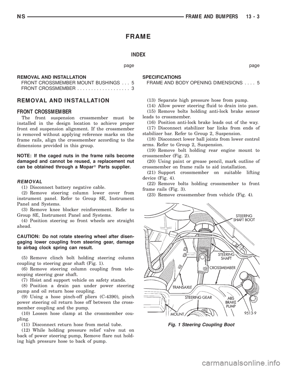
(5) Remove clinch bolt holding steering column
coupling to steering gear shaft (Fig. 1).
(6) Remove steering column coupling from tele-
scoping steering gear shaft.
(7) Hoist and support vehicle on safety stands.
(8) Position a drain pan under power steering
pump and oil return hose coupling.
(9) Using a hose pinch-off pliers (C-4390), pinch
power steering oil return hose off between the cross-
member coupling and the pump.
(10) Loosen hose clamp at the crossmember cou-
pling.
(11) Disconnect return hose from metal tube.
(12) While holding pressure relief valve nut on
back of power steering pump, Remove flare nut hold-
ing high pressure hose to back of pump.(13) Separate high pressure hose from pump.
(14) Allow power steering fluid to drain into pan.
(15) Remove bolts holding anti-lock brake sensor
leads to crossmember.
(16) Position anti-lock brake leads out of the way.
(17) Disconnect stabilizer bar links from ends of
stabilizer bar. Refer to Group 2, Suspension.
(18) Disconnect lower ball joints from lower control
arms. Refer to Group 2, Suspension.
(19) Remove bolt holding rear engine mount to
crossmember (Fig. 2).
(20) Using paint or grease pencil, mark outline of
crossmember on frame rails to aid installation.
(21) Support crossmember on suitable lifting
device (Fig. 4).
(22) Remove bolts holding crossmember to front
frame rails (Fig. 3).
(23) Remove crossmember from vehicle (Fig. 4).
Fig. 1 Steering Coupling Boot
NSFRAME AND BUMPERS 13 - 3
Page 1433 of 1938
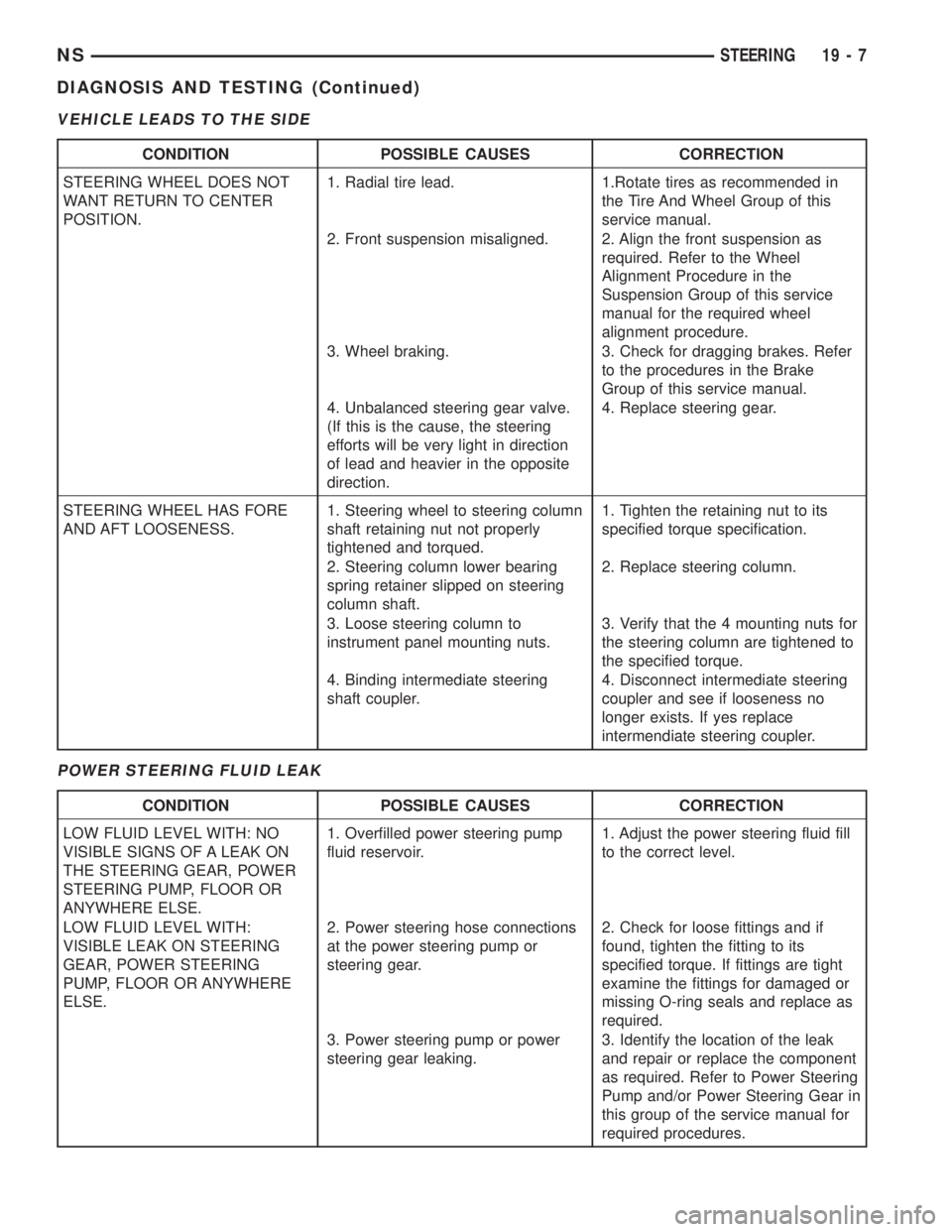
VEHICLE LEADS TO THE SIDE
POWER STEERING FLUID LEAK
CONDITION POSSIBLE CAUSES CORRECTION
STEERING WHEEL DOES NOT
WANT RETURN TO CENTER
POSITION.1. Radial tire lead. 1.Rotate tires as recommended in
the Tire And Wheel Group of this
service manual.
2. Front suspension misaligned. 2. Align the front suspension as
required. Refer to the Wheel
Alignment Procedure in the
Suspension Group of this service
manual for the required wheel
alignment procedure.
3. Wheel braking. 3. Check for dragging brakes. Refer
to the procedures in the Brake
Group of this service manual.
4. Unbalanced steering gear valve.
(If this is the cause, the steering
efforts will be very light in direction
of lead and heavier in the opposite
direction.4. Replace steering gear.
STEERING WHEEL HAS FORE
AND AFT LOOSENESS.1. Steering wheel to steering column
shaft retaining nut not properly
tightened and torqued.1. Tighten the retaining nut to its
specified torque specification.
2. Steering column lower bearing
spring retainer slipped on steering
column shaft.2. Replace steering column.
3. Loose steering column to
instrument panel mounting nuts.3. Verify that the 4 mounting nuts for
the steering column are tightened to
the specified torque.
4. Binding intermediate steering
shaft coupler.4. Disconnect intermediate steering
coupler and see if looseness no
longer exists. If yes replace
intermendiate steering coupler.
CONDITION POSSIBLE CAUSES CORRECTION
LOW FLUID LEVEL WITH: NO
VISIBLE SIGNS OF A LEAK ON
THE STEERING GEAR, POWER
STEERING PUMP, FLOOR OR
ANYWHERE ELSE.1. Overfilled power steering pump
fluid reservoir.1. Adjust the power steering fluid fill
to the correct level.
LOW FLUID LEVEL WITH:
VISIBLE LEAK ON STEERING
GEAR, POWER STEERING
PUMP, FLOOR OR ANYWHERE
ELSE.2. Power steering hose connections
at the power steering pump or
steering gear.2. Check for loose fittings and if
found, tighten the fitting to its
specified torque. If fittings are tight
examine the fittings for damaged or
missing O-ring seals and replace as
required.
3. Power steering pump or power
steering gear leaking.3. Identify the location of the leak
and repair or replace the component
as required. Refer to Power Steering
Pump and/or Power Steering Gear in
this group of the service manual for
required procedures.
NSSTEERING 19 - 7
DIAGNOSIS AND TESTING (Continued)
Page 1455 of 1938
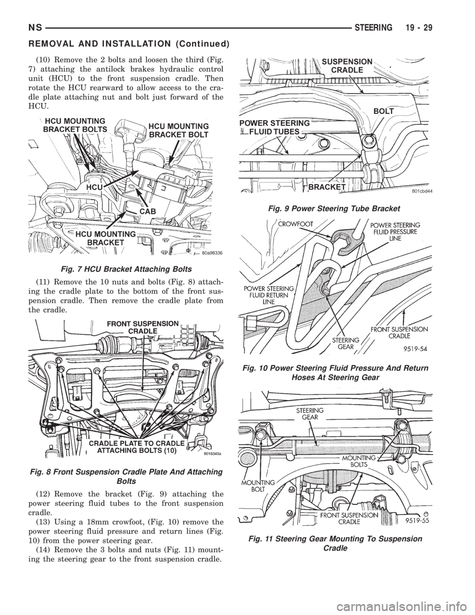
(10) Remove the 2 bolts and loosen the third (Fig.
7) attaching the antilock brakes hydraulic control
unit (HCU) to the front suspension cradle. Then
rotate the HCU rearward to allow access to the cra-
dle plate attaching nut and bolt just forward of the
HCU.
(11) Remove the 10 nuts and bolts (Fig. 8) attach-
ing the cradle plate to the bottom of the front sus-
pension cradle. Then remove the cradle plate from
the cradle.
(12) Remove the bracket (Fig. 9) attaching the
power steering fluid tubes to the front suspension
cradle.
(13) Using a 18mm crowfoot, (Fig. 10) remove the
power steering fluid pressure and return lines (Fig.
10) from the power steering gear.
(14) Remove the 3 bolts and nuts (Fig. 11) mount-
ing the steering gear to the front suspension cradle.
Fig. 7 HCU Bracket Attaching Bolts
Fig. 8 Front Suspension Cradle Plate And Attaching
Bolts
Fig. 9 Power Steering Tube Bracket
Fig. 10 Power Steering Fluid Pressure And Return
Hoses At Steering Gear
Fig. 11 Steering Gear Mounting To Suspension
Cradle
NSSTEERING 19 - 29
REMOVAL AND INSTALLATION (Continued)
Page 1491 of 1938
(2) To perform the dipstick tube fluid suction
method, use a suitable fluid suction device (Vaculay
or equivalent).
(3) Insert the fluid suction line into the dipstick
tube.
NOTE: Verify that the suction line is inserted to the
lowest point of the transaxle oil pan. This will
ensure complete evacuation of the fluid in the pan.
(4) Follow the manufacturers recommended proce-
dure and evacuate the fluid from the transaxle.
(5) Remove the suction line from the dipstick tube.
(6) Add 4 Quarts of Mopar ATF Plus 3 Type 7176
transaxle fluid.
(7) Start the engine and allow it to idle for a min-
imum of one minute. With the parking brake applied,
press your foot on the service brake and cycle the
transaxle from park to all gear positions ending in
neutral or park.
(8) Check the transaxle fluid level and add an
appropriate amount to bring the transaxle fluid level
to 3mm (1/8 in.) below the ADD mark on the dip-
stick.
(9) Recheck the fluid level after the transaxle is at
normal operating temperature. The level should be in
the HOT range.
TRANSAXLE OIL PAN DROP METHOD
This procedure involves removing the transaxle oil
pan to drain the transaxle fluid.
(1) Bring the vehicle up to normal operating tem-
perature. Drive the vehicle a minimum of 10 miles.
(2) Raise the vehicle on the hoist.
(3) Loosen the transaxle oil pan and drain the
fluid into a suitable container.
(4) Remove the pan and clean all sealant from the
pan and transaxle mating surfaces. Clean the mag-
net and the inside of the pan.
(5) Apply a 1/8 inch bead of Mopar RTV Sealant to
the mounting flange of the transaxle oil pan. Apply
RTV Sealant to the underside of the attaching bolts.
Attach the oil pan to the transaxle. Tighten the bolts
to 19 N²m (165 in. lbs.).
(6) Lower the vehicle and add 4 Quarts of Mopar
ATF Plus 3 Type 7176 transaxle fluid.
(7) Start the engine and allow it to idle for a min-
imum of one minute. With the parking brake applied,
press your foot on the service brake and cycle the
transaxle from park to all gear positions ending in
neutral or park.
(8) Check the transaxle fluid level and add an
appropriate amount to bring the transaxle fluid level
to 3mm (1/8 in.) below the ADD mark on the dip-
stick.
(9) Recheck the fluid level after the transaxle is at
normal operating temperature. The level should be inthe HOT range. Drive the vehicle a minimum of 10
miles.
(10) Raise the vehicle on the hoist.
(11) Check for leaks around the transaxle oil pan
sealing surfaces.
(12) Recheck the fluid level. The level should be in
the HOT range.
SEVERE USAGE SERVICE
If the vehicle exhibits any of the following symp-
toms, it is recommended that the transaxle oil and
filter be replaced.
²Transaxle oil discolored
²Transaxle oil has high mileage
²Oil feels grimy when rubbed between fingertips
²Poor shift quality
²Delayed gear engagement
²Vehicle shudder between shifts
TRANSAXLE OIL AND FILTER REPLACEMENT
This procedure involves changing the transaxle
fluid and filter, driving the vehicle for 10 miles and
changing the transaxle fluid a second time.
(1) Bring the vehicle up to normal operating tem-
perature. Drive the vehicle a minimum of 10 miles.
(2) Raise the vehicle on the hoist.
(3) Loosen the transaxle oil pan and drain the
fluid into a suitable container.
(4) Remove the pan and clean all sealant from the
pan and transaxle mating surfaces. Clean the mag-
net and the inside of the pan.
(5) Separate the filter and O-ring from the valve
body. Inspect the O-ring for cuts or improper instal-
lation. This could lead to delayed garage shifts.
(6) Install a new filter. Replace the O-ring as nec-
essary.
(7) Apply a 1/8 inch bead of Mopar RTV Sealant to
the mounting flange of the transaxle oil pan. Apply
RTV Sealant to the underside of the attaching bolts.
Attach the oil pan to the transaxle. Tighten the bolts
to 19 N²m (165 in. lbs.).
(8) Lower the vehicle and add 4 Quarts of Mopar
ATF Plus 3 Type 7176 transaxle fluid.
(9) Start the engine and allow it to idle for a min-
imum of one minute. With the parking brake applied,
press your foot on the service brake and cycle the
transaxle from park to all gear positions ending in
neutral or park.
(10) Check the transaxle fluid level and add an
appropriate amount to bring the transaxle fluid level
to 3mm (1/8 in.) below the ADD mark on the dip-
stick.
(11) Recheck the fluid level after the transaxle is
at normal operating temperature. The level should be
in the HOT range. Drive the vehicle a minimum of
10 miles.
(12) Raise the vehicle on the hoist.
NSTRANSAXLE AND POWER TRANSFER UNIT 21 - 17
SERVICE PROCEDURES (Continued)