headlamp CHRYSLER VOYAGER 2001 Owners Manual
[x] Cancel search | Manufacturer: CHRYSLER, Model Year: 2001, Model line: VOYAGER, Model: CHRYSLER VOYAGER 2001Pages: 4284, PDF Size: 83.53 MB
Page 1947 of 4284

SPECIFICATIONS
EXTERIOR LAMPS
CAUTION: Do not use bulbs other than those listed
in the Bulb Application Table. Damage to lamp can
result.
CAUTION: Do not touch halogen bulbs with fingers
or other oily surfaces. Bulb life will be reduced.
BULB APPLICATION TABLE
LAMP BULB
BACK-UP 3057
CENTER HIGH
MOUNTED STOP921
FRONT SIDE MARKER/
PARK/TURN3157A
FOG LAMP 9040
HEADLAMP 9007
LICENSE 168
TAIL, STOP 3057
TURN SIGNAL 3057
BRAKE LAMP SWITCH
DESCRIPTION
The brake lamp switch is located under the instru-
ment panel, at the brake pedal arm (Fig. 3). It has
three internal switches controlling various functions
of the vehicle. It's main function is to control opera-
tion of the vehicle's brake lamps. Other functions
include speed control deactivation, brake sense for
the antilock brake system and brake sense for the
brake transmission shift interlock.
CAUTION: The switch can only be adjusted once.
That is during initial installation of the switch. If the
switch is not adjusted properly or has been
removed for some service, a new switch must be
installed and adjusted.
OPERATION
When the brake pedal is pressed, the plunger on
the outside of the brake lamp switch extends out-
ward. This action opens or closes the contacts of the
three switches inside the brake lamp switch.
With the brake pedal is pressed down (plunger
extended), the switch for terminals 1 and 2 is closedcompleting the circuit. The switch for terminals 3
and 4 is open and so is the switch for 5 and 6.
When the brake pedal is released (plunger pushed
in), the three switches assume the opposite positions.
The switch for terminals 1 and 2 is now open while
the other two switches are now closed, completing
their circuits.
DIAGNOSIS AND TESTING - BRAKE LAMP
SWITCH
NOTE: Before proceeding with this diagnostic test,
verify the adjustment of the brake lamp switch to
rule out misadjustment. If misadjusted, replace the
switch. It cannot be readjusted.
If the electrical circuit has been tested and the
brake lamp switch is suspected of being faulty, it can
be tested using the following method.
(1) Remove the switch from the vehicle. Refer to
Removal And Installation in this section.
(2) With the switch in the released position (plung-
er extended), use an ohmmeter to test each of the
three internal switches as shown (Fig. 1). You should
achieve the results as listed in the figure.
(3) Gently push the plunger on the brake lamp
switch in until it stops.
(4) With the switch in this depressed position
(plunger pushed in), use an ohmmeter to test each of
the three internal switches as shown (Fig. 2). You
should achieve the results as listed in the figure.
If you do not achieve the results as listed in both
figures, the switch is faulty and must be replaced.
Refer to Removal And Installation in this section.
If the switch is found to be operating properly, do
not reinstall it, replace the switch. Refer to Removal
And Installation in this section.
Fig. 1 Switch Test - Released Position
RSLAMPS/LIGHTING - EXTERIOR8L-7
Page 1950 of 4284

FOG LAMP UNIT
REMOVAL
(1) Disconnect and isolate the battery negative
cable.
(2) From behind the bumper fascia, disconnect the
wire harness from the fog lamp bulb (Fig. 7).
(3) Remove mounting nuts.
INSTALLATION
(1) Install mounting nuts.
(2) Reconnect the wire harness to the fog lamp
bulb.
(3) Reconnect the battery negative cable.
ADJUSTMENT
FOG LAMP ALIGNMENT
Prepare an alignment screen. (Refer to 8 - ELEC-
TRICAL/LAMPS/LIGHTING - EXTERIOR/HEAD-
LAMP UNIT - ADJUSTMENTS). A properly aligned
fog lamp will project a pattern on the alignment
screen 100 mm (4 in.) below the fog lamp center line
and straight ahead (Fig. 8). To improve visual inter-
pretation of the fog lamp pattern on the alignment
screen, the headlamps should be in the ªoffº position.
The fog lamps are adjusted by a adjustment screw
located through the lens on Dodge vehicles, and by a
knob on the back of the lamp on Chrysler vehicles.
Fig. 8 Fog Lamp Alignment
1 - HIGH INTENSITY AREA
2 - CENTER OF VEHICLE
3 - HORIZONTAL CENTER OF FOG LAMP
4 - 100MM (4 IN.)5 - 7.62 METERS (25 FT.)
6 - FRONT OF FOG LAMP
8L - 10 LAMPS/LIGHTING - EXTERIORRS
Page 1951 of 4284

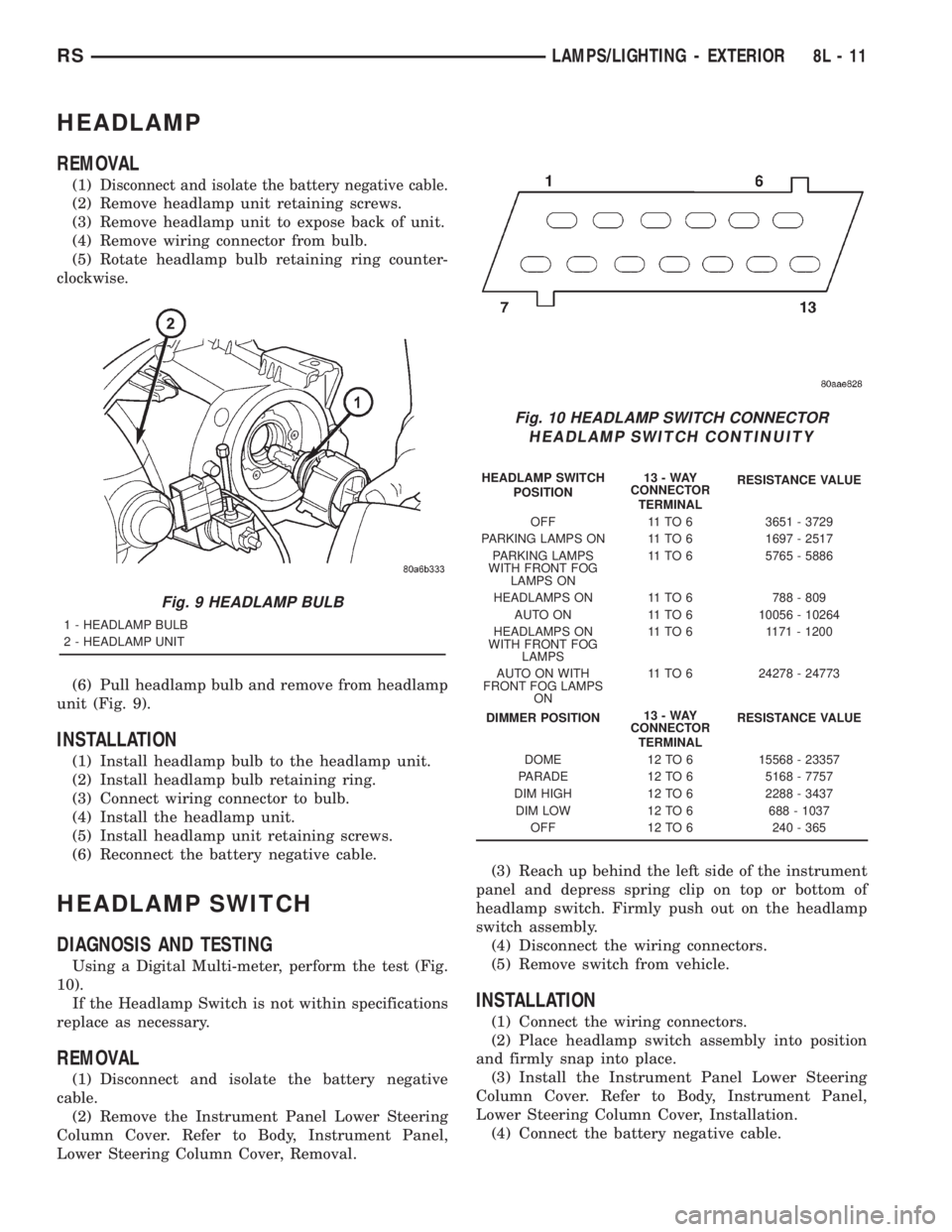
HEADLAMP
REMOVAL
(1)Disconnect and isolate the battery negative cable.
(2) Remove headlamp unit retaining screws.
(3) Remove headlamp unit to expose back of unit.
(4) Remove wiring connector from bulb.
(5) Rotate headlamp bulb retaining ring counter-
clockwise.
(6) Pull headlamp bulb and remove from headlamp
unit (Fig. 9).
INSTALLATION
(1) Install headlamp bulb to the headlamp unit.
(2) Install headlamp bulb retaining ring.
(3) Connect wiring connector to bulb.
(4) Install the headlamp unit.
(5) Install headlamp unit retaining screws.
(6) Reconnect the battery negative cable.
HEADLAMP SWITCH
DIAGNOSIS AND TESTING
Using a Digital Multi-meter, perform the test (Fig.
10).
If the Headlamp Switch is not within specifications
replace as necessary.
REMOVAL
(1) Disconnect and isolate the battery negative
cable.
(2) Remove the Instrument Panel Lower Steering
Column Cover. Refer to Body, Instrument Panel,
Lower Steering Column Cover, Removal.(3) Reach up behind the left side of the instrument
panel and depress spring clip on top or bottom of
headlamp switch. Firmly push out on the headlamp
switch assembly.
(4) Disconnect the wiring connectors.
(5) Remove switch from vehicle.
INSTALLATION
(1) Connect the wiring connectors.
(2) Place headlamp switch assembly into position
and firmly snap into place.
(3) Install the Instrument Panel Lower Steering
Column Cover. Refer to Body, Instrument Panel,
Lower Steering Column Cover, Installation.
(4) Connect the battery negative cable.
Fig. 9 HEADLAMP BULB
1 - HEADLAMP BULB
2 - HEADLAMP UNIT
Fig. 10 HEADLAMP SWITCH CONNECTOR
HEADLAMP SWITCH CONTINUITY
HEADLAMP SWITCH
POSITION13-WAY
CONNECTOR
TERMINALRESISTANCE VALUE
OFF 11 TO 6 3651 - 3729
PARKING LAMPS ON 11 TO 6 1697 - 2517
PARKING LAMPS
WITH FRONT FOG
LAMPS ON11 TO 6 5765 - 5886
HEADLAMPS ON 11 TO 6 788 - 809
AUTO ON 11 TO 6 10056 - 10264
HEADLAMPS ON
WITH FRONT FOG
LAMPS11 TO 6 1171 - 1200
AUTO ON WITH
FRONT FOG LAMPS
ON11 TO 6 24278 - 24773
DIMMER POSITION13-WAY
CONNECTOR
TERMINALRESISTANCE VALUE
DOME 12 TO 6 15568 - 23357
PARADE 12 TO 6 5168 - 7757
DIM HIGH 12 TO 6 2288 - 3437
DIM LOW 12 TO 6 688 - 1037
OFF 12 TO 6 240 - 365
RSLAMPS/LIGHTING - EXTERIOR8L-11
Page 1952 of 4284

HEADLAMP UNIT
REMOVAL
(1) Disconnect and isolate the battery negative
cable.
(2) Remove the three retaining screws (Fig. 11).
(3) Disconnect the wiring harness from the bulbs
(Fig. 12).(4) Remove wire harness retainer from back of
headlamp unit.
(5) Remove the headlamp unit.INSTALLATION
(1) Reconnect wire harness to the bulbs.
(2) Install wire harness retainer to headlamp unit.
(3) Install the three retaining screws.
(4) Reconnect the battery negative cable.
ADJUSTMENT
HEADLAMP ALIGNMENT PREPARATION
(1) Verify headlamp dimmer switch and high beam
indicator operation.
(2) Inspect and correct damaged or defective com-
ponents that could interfere with proper headlamp
alignment.
(3) Verify proper tire inflation.
(4) Clean headlamp lenses.
(5) Verify that luggage area is loaded as the vehi-
cle is routinely used.
(6) Fuel tank should be FULL. Add 2.94 kg (6.5
lbs.) of weight over the fuel tank for each estimated
gallon of missing fuel.
ALIGNMENT SCREEN PREPARATION
(1) Position vehicle on a level surface perpendicu-
lar to a flat wall 7.62 meters (25 ft.) away from front
of headlamp lens (Fig. 13).
(2) If necessary, tape a line on the floor 7.62
meters (25 ft.) away from and parallel to the wall.
(3) Rock vehicle side-to-side three times and allow
suspension to stabilize.
(4) Jounce front suspension three times by pushing
downward on front bumper and releasing.
(5) Measure the distance from the center of head-
lamp lens to the floor. Transfer measurement to the
alignment screen (with tape). Use this line for
up/down adjustment reference.
Fig. 11 HEADLAMP FASTENERS
1 - HEADLAMP RETAINING SCREW
2 - HEADLAMP UNIT
Fig. 12 HEADLAMP ASSEMBLY
1 - HEADLAMP UNIT
2 - HEADLAMP BULB
3 - PARK/TURN SIGNAL BULB
4 - WIRE HARNESS RETAINER
8L - 12 LAMPS/LIGHTING - EXTERIORRS
Page 1953 of 4284

Fig. 13 Headlamp Alignment Screen
1 - CENTER OF HEADLAMPS
2 - HEADLAMP BEAM3 - FRONT OF HEADLAMP
4 - 7.62 METERS (25 FT.)
RSLAMPS/LIGHTING - EXTERIOR8L-13
HEADLAMP UNIT (Continued)
Page 1954 of 4284

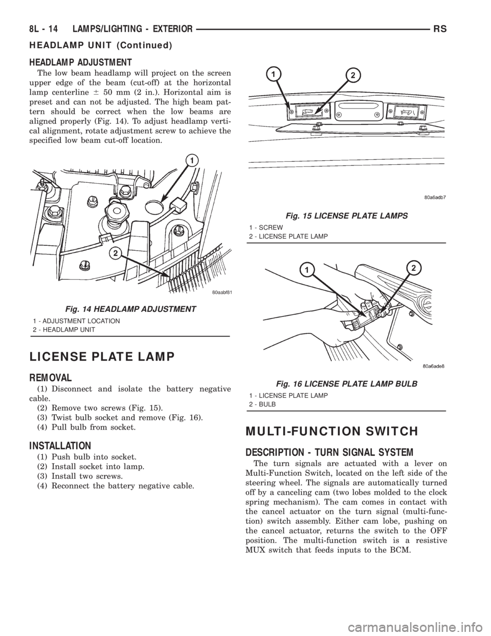
HEADLAMP ADJUSTMENT
The low beam headlamp will project on the screen
upper edge of the beam (cut-off) at the horizontal
lamp centerline650 mm (2 in.). Horizontal aim is
preset and can not be adjusted. The high beam pat-
tern should be correct when the low beams are
aligned properly (Fig. 14). To adjust headlamp verti-
cal alignment, rotate adjustment screw to achieve the
specified low beam cut-off location.
LICENSE PLATE LAMP
REMOVAL
(1) Disconnect and isolate the battery negative
cable.
(2) Remove two screws (Fig. 15).
(3) Twist bulb socket and remove (Fig. 16).
(4) Pull bulb from socket.
INSTALLATION
(1) Push bulb into socket.
(2) Install socket into lamp.
(3) Install two screws.
(4) Reconnect the battery negative cable.
MULTI-FUNCTION SWITCH
DESCRIPTION - TURN SIGNAL SYSTEM
The turn signals are actuated with a lever on
Multi-Function Switch, located on the left side of the
steering wheel. The signals are automatically turned
off by a canceling cam (two lobes molded to the clock
spring mechanism). The cam comes in contact with
the cancel actuator on the turn signal (multi-func-
tion) switch assembly. Either cam lobe, pushing on
the cancel actuator, returns the switch to the OFF
position. The multi-function switch is a resistive
MUX switch that feeds inputs to the BCM.
Fig. 14 HEADLAMP ADJUSTMENT
1 - ADJUSTMENT LOCATION
2 - HEADLAMP UNIT
Fig. 15 LICENSE PLATE LAMPS
1 - SCREW
2 - LICENSE PLATE LAMP
Fig. 16 LICENSE PLATE LAMP BULB
1 - LICENSE PLATE LAMP
2 - BULB
8L - 14 LAMPS/LIGHTING - EXTERIORRS
HEADLAMP UNIT (Continued)
Page 1955 of 4284

OPERATION - TURN SIGNAL SYSTEM
Lane change signaling is actuated by applying par-
tial turn signal stalk movement toward the direction
desired until the indicator lamps flashes in the
instrument cluster. When the switch stalk is released
the stalk will spring back into the neutral position
turning OFF the turn signal.
With the ignition switch ON and the turn signal
switch stalk actuated left or right, current flows
through the:
²Multi-function switch
²Body Control Module
²Integrated Power Module (IPM)
²Turn indicator lamp
²Front and rear turn signal bulbs.
A chime will sound after the vehicle has traveled a
distance of approximately 0.5 mile and a speed of 15
mph, with the turn signal ON.
DIAGNOSIS AND TESTING - MULTI-FUNCTION
SWITCH
To test turn signal, headlamp beam select and opti-
cal horn portion of the multi-function switch:
(1) Remove the multi-function switch, refer to
Electrical, Lamps/Lighting - Exterior, Multi-Function
Switch, Removal, and Installation.
(2) Using an ohmmeter check the continuity read-
ings between multi-function switch pins. Refer to
Wiring Diagrams for proper pin numbers and the
table.
MULTI-FUNCTION SWITCH CONTINUITY
SWITCH POSITION CONTINUITY BETWEEN
LEFT 2 AND 3
RIGHT 2 AND 3
OPTICAL HORN 2 AND 4
HI BEAM 2 AND 4
REMOVAL
(1) Disconnect and isolate battery negative cable.
(2) Remove upper and lower steering column
shrouds. Refer to Steering, Column, Shroud,
Removal.
(3) Disconnect wire connector from back of multi-
function switch.
(4) Remove screws holding multi-function switch to
steering column adapter collar.
(5) Remove the multi-function switch.
INSTALLATION
(1) Position the switch on to the steering column.
(2) Install the two retaining screws.
(3) Connect the wire harness connector.
(4) Install the upper and lower steering column
shrouds. Refer to Steering, Column, Shroud, Installa-
tion.
(5) Connect the battery negative cable.
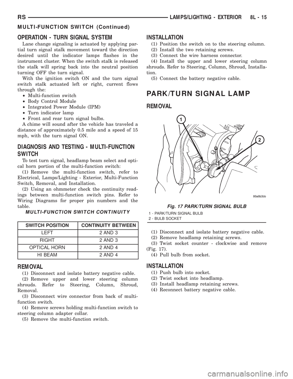
PARK/TURN SIGNAL LAMP
REMOVAL
(1) Disconnect and isolate battery negative cable.
(2) Remove headlamp retaining screws.
(3) Twist socket counter - clockwise and remove
(Fig. 17).
(4) Pull bulb from socket.
INSTALLATION
(1) Push bulb into socket.
(2) Twist socket into headlamp.
(3) Install headlamp retaining screws.
(4) Reconnect battery negative cable.
Fig. 17 PARK/TURN SIGNAL BULB
1 - PARK/TURN SIGNAL BULB
2 - BULB SOCKET
RSLAMPS/LIGHTING - EXTERIOR8L-15
MULTI-FUNCTION SWITCH (Continued)
Page 1961 of 4284

LAMPS
TABLE OF CONTENTS
page page
LAMPS/LIGHTING - EXTERIOR
SPECIFICATIONS.........................1
FOG LAMP
REMOVAL...............................1
INSTALLATION............................2
FOG LAMP UNIT
ADJUSTMENTS...........................2
FRONT POSITION LAMP
REMOVAL...............................3
INSTALLATION............................3
HEADLAMP
REMOVAL...............................3
INSTALLATION............................3
HEADLAMP LEVELING MOTOR
DIAGNOSIS AND TESTING..................4
HEADLAMP LEVELING MOTOR.............4
REMOVAL...............................4
INSTALLATION............................4
HEADLAMP LEVELING SWITCH
DESCRIPTION............................4DIAGNOSIS AND TESTING..................4
HEADLAMP LEVELING SWITCH............4
HEADLAMP SWITCH
DIAGNOSIS AND TESTING..................5
HEADLAMP SWITCH.....................5
HEADLAMP UNIT
ADJUSTMENTS...........................6
PARK/TURN SIGNAL LAMP
REMOVAL...............................7
INSTALLATION............................7
REAR FOG LAMP
DESCRIPTION............................7
REPEATER LAMP
REMOVAL...............................7
INSTALLATION............................7
TAIL LAMP
REMOVAL...............................8
INSTALLATION............................8
LAMPS/LIGHTING - EXTERIOR
SPECIFICATIONS
EXTERIOR LAMPS
BULB APPLICATION CHART
LAMP BULB TYPE
HEADLAMP H7
FRONT POSITION W5W
FRONT TURN SIGNAL PY21W
SIDE REPEATER T4W
LICENSE PLATE W5W/168
REAR TAIL AND STOP P21/5W
REAR TURN SIGNAL PY21W
BACK-UP P21W
REAR FOG P21W
CENTER HIGH
MOUNTED STOP LAMPW16W/921
For additional bulb applications refer to the domestic
Lamps section of the service manual.
FOG LAMP
REMOVAL
(1) Disconnect and isolate the battery negative
cable.
(2) Remove access cover from under bumper fascia.
(3) Disengage spring clip from fog lamp (Fig. 1).
Fig. 1 FOG LAMP
1 - SPRING CLIP
2 - FOG LAMP BULB
RGLAMPS8La-1
Page 1962 of 4284

(4) Remove bulb from lamp.
(5) Disconnect wire harness connector.
INSTALLATION
(1) Connect wire harness connector.
(2) Install bulb to lamp.
(3) Engage spring clip to fog lamp.
(4) Install access cover under bumper fascia.
(5) Connect battery negative cable.
FOG LAMP UNIT
ADJUSTMENT
FOG LAMP ALIGNMENT
Prepare an alignment screen. (Refer to 8 - ELEC-
TRICAL/LAMPS/LIGHTING - EXTERIOR/HEAD-
LAMP UNIT - ADJUSTMENTS). A properly aligned
fog lamp will project a pattern on the alignment
screen 200 mm (8 in.) below the fog lamp center line
and straight ahead (Fig. 2). To improve visual inter-
pretation of the fog lamp pattern on the alignment
screen, the headlamps should be in the ªoffº position.
The fog lamps are adjusted by a adjustment screw
located on the underside of the fog lamp unit.
Fig. 2 FOG LAMP ALIGNMENT
1 - HIGH INTENSITY AREA
2 - CENTER OF VEHICLE
3 - HORIZONTAL CENTER OF FOG LAMP4 - 200 MM
5 - 10 METERS
6 - FRONT OF FOG LAMP
8La - 2 LAMPSRG
FOG LAMP (Continued)
Page 1963 of 4284

FRONT POSITION LAMP
REMOVAL
(1) Disconnect and isolate the battery negative
cable.
(2) Remove the headlamp unit (Fig. 3).
(3) Remove the plastic cover from the back of the
headlamp unit.
(4) Pull front position lamp socket from headlamp
unit.
(5) Pull bulb straight out of socket.
INSTALLATION
(1) Push bulb into the bulb socket.
(2) Insert bulb socket into headlamp unit.
(3) Install cover to the back of the headlamp unit.
(4) Install the headlamp unit.
(5) Connect the battery negative cable.
HEADLAMP
REMOVAL
(1) Disconnect and isolate the battery negative
cable.
(2) Remove the headlamp unit.
(3) Remove the cover (high beam lamp) or rubber
boot (low beam lamp) to access bulbs (Fig. 4).
(4) Disconnect the wire harness connector.
(5) Disengage spring clip from headlamp.
(6) Pull headlamp bulb from back of headlamp
unit.
INSTALLATION
(1) Insert headlamp bulb into headlamp unit.
(2) Engage spring clip to headlamp.
(3) Connect wire harness connector.
(4) Install the cover (high beam lamp) or rubber
boot (low beam lamp) to headlamp unit.
(5) Install the headlamp unit.
(6) Connect the battery negative cable.
Fig. 3 FRONT POSITION LAMP
1 - TURN SIGNAL LAMP
2 - HIGH BEAM LAMP
3 - FRONT POSITION LAMP
4 - LOW BEAM LAMP
Fig. 4 HEADLAMP UNIT
1 - HIGH BEAM LAMP
2 - HEADLAMP LEVELING MOTOR
3 - LOW BEAM LAMP
4 - TURN LAMP
RGLAMPS8La-3