set clock CHRYSLER VOYAGER 2001 Owner's Manual
[x] Cancel search | Manufacturer: CHRYSLER, Model Year: 2001, Model line: VOYAGER, Model: CHRYSLER VOYAGER 2001Pages: 4284, PDF Size: 83.53 MB
Page 310 of 4284

TEST ACTION APPLICABILITY
4 Turn the ignition off.
Disconnect the Rear Automatic Temperature Control Switch harness connector.
Disconnect the ATC C2 harness connector.
Turn the ignition on.
Measure the voltage of the KDB Data circuit.
Is the voltage above 1.0 volt?All
Ye s®Repair the KDB Data circuit for a short to voltage.
With the DRBIIIt, reset the ATC after repair/replacement is
complete.
Perform BODY VERIFICATION TEST - VER 1.
No®Go To 5
5 Turn the ignition off.
Disconnect the Rear Automatic Temperature Control Switch harness connector.
Use Scope input cable CH7058, Cable to Probe adapter CH7062, and the red and
black test probes.
Connect the scope input cable to the channel one connector on the DRB. Attach the
red and black leads and the cable to probe adapter to the scope input cable.
Select Lab Scope.
Select Live.
Select 12 volt square wave.
Press F2 for Scope.
Press F2 and use the arrows to set the voltage range to 20 volts, the Offset to 4.0, and
the Probe to x10. Press F2 again and set the divisions to 40ms/Div, then press F2
again when complete.
Connect the Black lead to the chassis ground. Connect the Red lead to the KDB Clock
circuit in the Rear Automatic Temperature Control Switch harness connector.
Turn the ignition on.
Observe the voltage display on the DRB Lab Scope.
NOTE: The lab scope pattern should look similar to the example given in the
support material and cycle from approximately 0 volts to 8.0 volts.
Did the lab scope pattern and voltage react as noted above?All
Ye s®Go To 6
No®Go To 7
6 If there are no possible causes remaining, view repair. All
Repair
Replace the Rear Automatic Temperature Control Switch.
With the DRBIIIt, reset the ATC after repair/replacement is
complete.
Perform BODY VERIFICATION TEST - VER 1.
7 Turn the ignition off.
Disconnect the Rear Automatic Temperature Control Switch harness connector.
Disconnect the ATC C2 harness connector.
Turn the ignition on.
Measure the voltage of the KDB Clock circuit.
Is the voltage above 1.0 volt?All
Ye s®Repair the KDB Clock circuit for a short to voltage.
With the DRBIIIt, reset the ATC after repair/replacement is
complete.
Perform BODY VERIFICATION TEST - VER 1.
No®Go To 8
281
AUTOMATIC TEMPERATURE CONTROL
REAR KEYBOARD FAULT (ACTIVE) ÐContinued
Page 311 of 4284
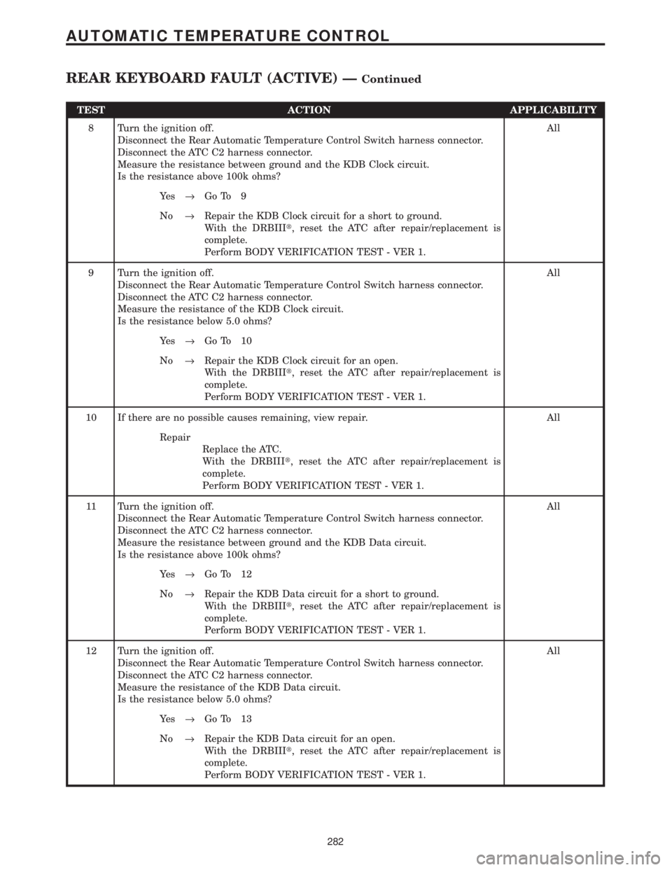
TEST ACTION APPLICABILITY
8 Turn the ignition off.
Disconnect the Rear Automatic Temperature Control Switch harness connector.
Disconnect the ATC C2 harness connector.
Measure the resistance between ground and the KDB Clock circuit.
Is the resistance above 100k ohms?All
Ye s®Go To 9
No®Repair the KDB Clock circuit for a short to ground.
With the DRBIIIt, reset the ATC after repair/replacement is
complete.
Perform BODY VERIFICATION TEST - VER 1.
9 Turn the ignition off.
Disconnect the Rear Automatic Temperature Control Switch harness connector.
Disconnect the ATC C2 harness connector.
Measure the resistance of the KDB Clock circuit.
Is the resistance below 5.0 ohms?All
Ye s®Go To 10
No®Repair the KDB Clock circuit for an open.
With the DRBIIIt, reset the ATC after repair/replacement is
complete.
Perform BODY VERIFICATION TEST - VER 1.
10 If there are no possible causes remaining, view repair. All
Repair
Replace the ATC.
With the DRBIIIt, reset the ATC after repair/replacement is
complete.
Perform BODY VERIFICATION TEST - VER 1.
11 Turn the ignition off.
Disconnect the Rear Automatic Temperature Control Switch harness connector.
Disconnect the ATC C2 harness connector.
Measure the resistance between ground and the KDB Data circuit.
Is the resistance above 100k ohms?All
Ye s®Go To 12
No®Repair the KDB Data circuit for a short to ground.
With the DRBIIIt, reset the ATC after repair/replacement is
complete.
Perform BODY VERIFICATION TEST - VER 1.
12 Turn the ignition off.
Disconnect the Rear Automatic Temperature Control Switch harness connector.
Disconnect the ATC C2 harness connector.
Measure the resistance of the KDB Data circuit.
Is the resistance below 5.0 ohms?All
Ye s®Go To 13
No®Repair the KDB Data circuit for an open.
With the DRBIIIt, reset the ATC after repair/replacement is
complete.
Perform BODY VERIFICATION TEST - VER 1.
282
AUTOMATIC TEMPERATURE CONTROL
REAR KEYBOARD FAULT (ACTIVE) ÐContinued
Page 1614 of 4284
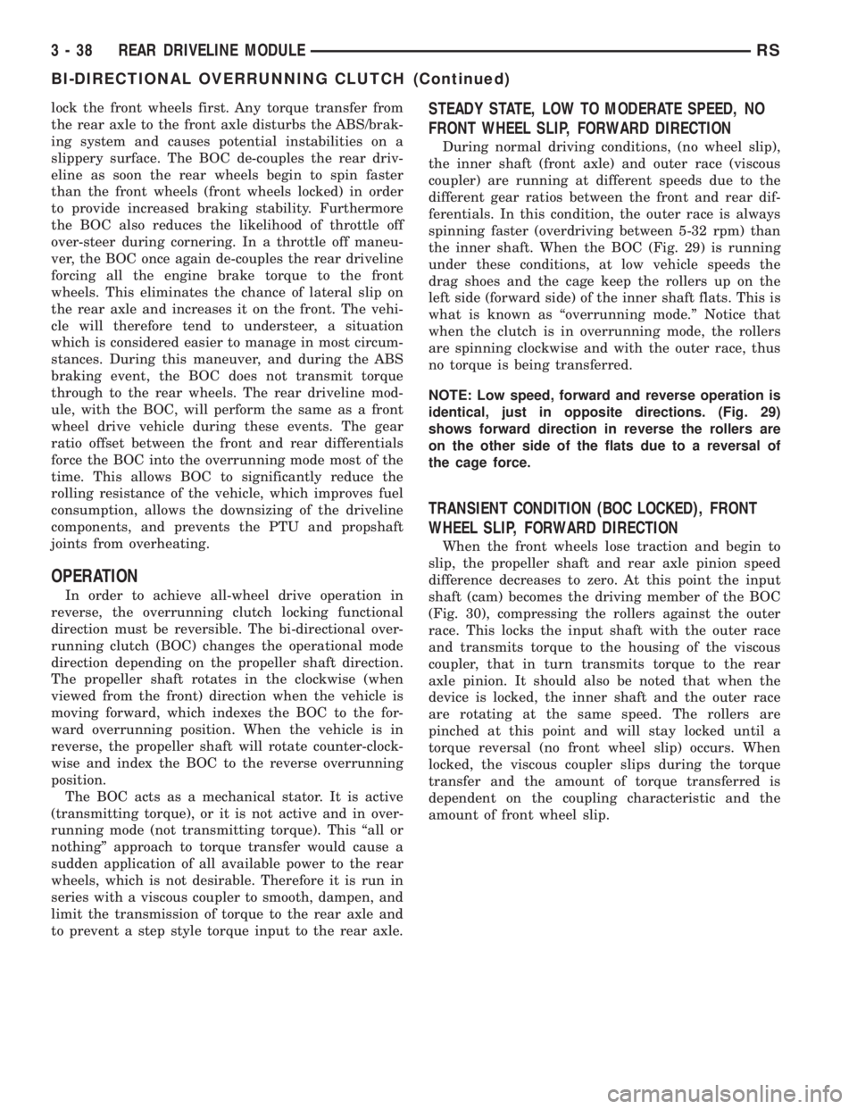
lock the front wheels first. Any torque transfer from
the rear axle to the front axle disturbs the ABS/brak-
ing system and causes potential instabilities on a
slippery surface. The BOC de-couples the rear driv-
eline as soon the rear wheels begin to spin faster
than the front wheels (front wheels locked) in order
to provide increased braking stability. Furthermore
the BOC also reduces the likelihood of throttle off
over-steer during cornering. In a throttle off maneu-
ver, the BOC once again de-couples the rear driveline
forcing all the engine brake torque to the front
wheels. This eliminates the chance of lateral slip on
the rear axle and increases it on the front. The vehi-
cle will therefore tend to understeer, a situation
which is considered easier to manage in most circum-
stances. During this maneuver, and during the ABS
braking event, the BOC does not transmit torque
through to the rear wheels. The rear driveline mod-
ule, with the BOC, will perform the same as a front
wheel drive vehicle during these events. The gear
ratio offset between the front and rear differentials
force the BOC into the overrunning mode most of the
time. This allows BOC to significantly reduce the
rolling resistance of the vehicle, which improves fuel
consumption, allows the downsizing of the driveline
components, and prevents the PTU and propshaft
joints from overheating.
OPERATION
In order to achieve all-wheel drive operation in
reverse, the overrunning clutch locking functional
direction must be reversible. The bi-directional over-
running clutch (BOC) changes the operational mode
direction depending on the propeller shaft direction.
The propeller shaft rotates in the clockwise (when
viewed from the front) direction when the vehicle is
moving forward, which indexes the BOC to the for-
ward overrunning position. When the vehicle is in
reverse, the propeller shaft will rotate counter-clock-
wise and index the BOC to the reverse overrunning
position.
The BOC acts as a mechanical stator. It is active
(transmitting torque), or it is not active and in over-
running mode (not transmitting torque). This ªall or
nothingº approach to torque transfer would cause a
sudden application of all available power to the rear
wheels, which is not desirable. Therefore it is run in
series with a viscous coupler to smooth, dampen, and
limit the transmission of torque to the rear axle and
to prevent a step style torque input to the rear axle.
STEADY STATE, LOW TO MODERATE SPEED, NO
FRONT WHEEL SLIP, FORWARD DIRECTION
During normal driving conditions, (no wheel slip),
the inner shaft (front axle) and outer race (viscous
coupler) are running at different speeds due to the
different gear ratios between the front and rear dif-
ferentials. In this condition, the outer race is always
spinning faster (overdriving between 5-32 rpm) than
the inner shaft. When the BOC (Fig. 29) is running
under these conditions, at low vehicle speeds the
drag shoes and the cage keep the rollers up on the
left side (forward side) of the inner shaft flats. This is
what is known as ªoverrunning mode.º Notice that
when the clutch is in overrunning mode, the rollers
are spinning clockwise and with the outer race, thus
no torque is being transferred.
NOTE: Low speed, forward and reverse operation is
identical, just in opposite directions. (Fig. 29)
shows forward direction in reverse the rollers are
on the other side of the flats due to a reversal of
the cage force.
TRANSIENT CONDITION (BOC LOCKED), FRONT
WHEEL SLIP, FORWARD DIRECTION
When the front wheels lose traction and begin to
slip, the propeller shaft and rear axle pinion speed
difference decreases to zero. At this point the input
shaft (cam) becomes the driving member of the BOC
(Fig. 30), compressing the rollers against the outer
race. This locks the input shaft with the outer race
and transmits torque to the housing of the viscous
coupler, that in turn transmits torque to the rear
axle pinion. It should also be noted that when the
device is locked, the inner shaft and the outer race
are rotating at the same speed. The rollers are
pinched at this point and will stay locked until a
torque reversal (no front wheel slip) occurs. When
locked, the viscous coupler slips during the torque
transfer and the amount of torque transferred is
dependent on the coupling characteristic and the
amount of front wheel slip.
3 - 38 REAR DRIVELINE MODULERS
BI-DIRECTIONAL OVERRUNNING CLUTCH (Continued)
Page 1756 of 4284
DIAGNOSIS AND TESTING - ENGINE COOLANT
THERMOSTAT
The thermostat is operated by a wax filled cham-
ber (pellet) which is sealed. When heated coolant
reaches a predetermined temperature the wax pellet
expands enough to overcome the closing spring and
water pump pressure, which forces the valve to open.
Coolant leakage into the pellet will cause a thermo-
stat to fail open. Do not attempt to free up a thermo-
stat with a screwdriver.
Thermostat diagnostics is included in powertrain
control module's (PCM) programing for on-board
diagnosis. The malfunction indicator light (MIL) will
illuminate and a diagnostic trouble code (DTC) will
be set when an ªopen too soonº condition occurs. Do
not change a thermostat for lack of heater perfor-
mance or temperature gauge position, unless a DTC
is present. For other probable causes, (Refer to 7 -
COOLING/ENGINE - DIAGNOSIS AND TESTING) .
Thermostat failing shut is the normal long term
mode of failure, and normally, only on high mileage
vehicles. The temperature gauge will indicate this
(Refer to 7 - COOLING/ENGINE - DIAGNOSIS AND
TESTING) .
ENGINE COOLANT
THERMOSTAT - 2.4L
REMOVAL
(1) Drain cooling system below the thermostat
level. (Refer to 7 - COOLING - STANDARD PROCE-
DURE)
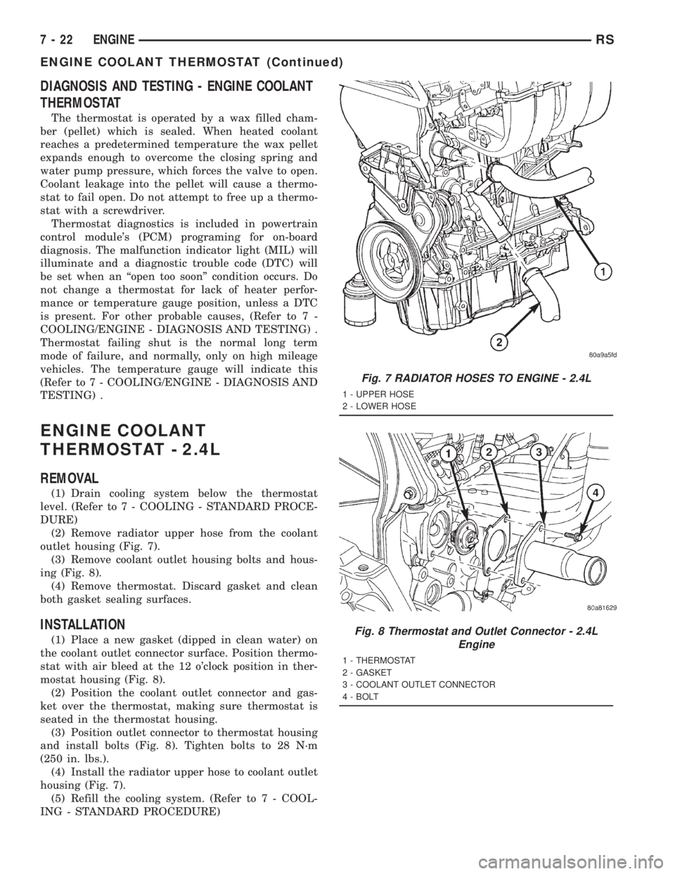
(2) Remove radiator upper hose from the coolant
outlet housing (Fig. 7).
(3) Remove coolant outlet housing bolts and hous-
ing (Fig. 8).
(4) Remove thermostat. Discard gasket and clean
both gasket sealing surfaces.
INSTALLATION
(1) Place a new gasket (dipped in clean water) on
the coolant outlet connector surface. Position thermo-
stat with air bleed at the 12 o'clock position in ther-
mostat housing (Fig. 8).
(2) Position the coolant outlet connector and gas-
ket over the thermostat, making sure thermostat is
seated in the thermostat housing.
(3) Position outlet connector to thermostat housing
and install bolts (Fig. 8). Tighten bolts to 28 N´m
(250 in. lbs.).
(4) Install the radiator upper hose to coolant outlet
housing (Fig. 7).
(5) Refill the cooling system. (Refer to 7 - COOL-
ING - STANDARD PROCEDURE)
Fig. 7 RADIATOR HOSES TO ENGINE - 2.4L
1 - UPPER HOSE
2 - LOWER HOSE
Fig. 8 Thermostat and Outlet Connector - 2.4L
Engine
1 - THERMOSTAT
2 - GASKET
3 - COOLANT OUTLET CONNECTOR
4 - BOLT
7 - 22 ENGINERS
ENGINE COOLANT THERMOSTAT (Continued)
Page 1805 of 4284
AUDIO
TABLE OF CONTENTS
page page
AUDIO
DESCRIPTION............................1
OPERATION.............................1
DIAGNOSIS AND TESTING..................1
ANTENNA BODY & CABLE
DESCRIPTION............................3
OPERATION.............................3
DIAGNOSIS AND TESTING..................3
REMOVAL...............................4
INSTALLATION............................4
CD CHANGER
DESCRIPTION............................6
OPERATION.............................6
REMOVAL...............................6
INSTALLATION............................6
CHOKE
DIAGNOSIS AND TESTING..................6
D-PILLAR SPEAKER
REMOVAL...............................6
INSTALLATION............................7
DASH PANEL SPEAKER
REMOVAL...............................7INSTALLATION............................7
DOOR MOUNTED SPEAKER
REMOVAL...............................7
INSTALLATION............................7
QUARTER PANEL SPEAKER
REMOVAL...............................8
INSTALLATION............................8
RADIO
DIAGNOSIS AND TESTING..................8
REMOVAL...............................9
INSTALLATION............................9
RADIO NOISE SUPPRESSION COMPONENTS
DESCRIPTION............................9
OPERATION.............................9
REMOTE SWITCHES
DESCRIPTION...........................10
OPERATION.............................10
DIAGNOSIS AND TESTING.................11
REMOVAL..............................11
INSTALLATION...........................12
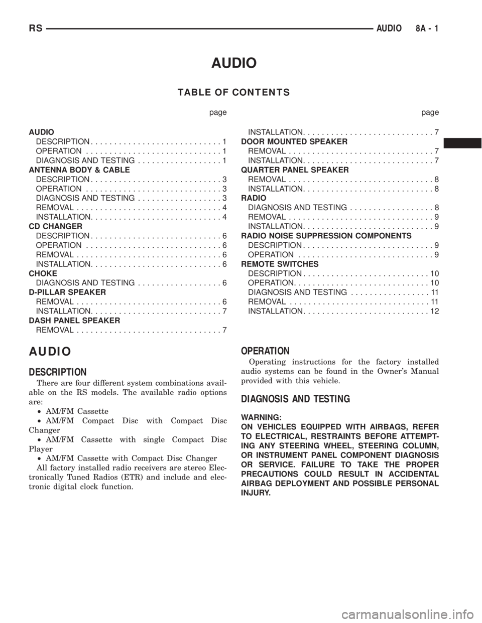
AUDIO
DESCRIPTION
There are four different system combinations avail-
able on the RS models. The available radio options
are:
²AM/FM Cassette
²AM/FM Compact Disc with Compact Disc
Changer
²AM/FM Cassette with single Compact Disc
Player
²AM/FM Cassette with Compact Disc Changer
All factory installed radio receivers are stereo Elec-
tronically Tuned Radios (ETR) and include and elec-
tronic digital clock function.
OPERATION
Operating instructions for the factory installed
audio systems can be found in the Owner's Manual
provided with this vehicle.
DIAGNOSIS AND TESTING
WARNING:
ON VEHICLES EQUIPPED WITH AIRBAGS, REFER
TO ELECTRICAL, RESTRAINTS BEFORE ATTEMPT-
ING ANY STEERING WHEEL, STEERING COLUMN,
OR INSTRUMENT PANEL COMPONENT DIAGNOSIS
OR SERVICE. FAILURE TO TAKE THE PROPER
PRECAUTIONS COULD RESULT IN ACCIDENTAL
AIRBAG DEPLOYMENT AND POSSIBLE PERSONAL
INJURY.
RSAUDIO8A-1
Page 1814 of 4284
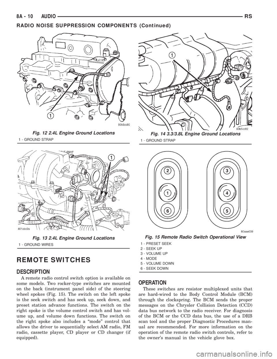
REMOTE SWITCHES
DESCRIPTION
A remote radio control switch option is available on
some models. Two rocker-type switches are mounted
on the back (instrument panel side) of the steering
wheel spokes (Fig. 15). The switch on the left spoke
is the seek switch and has seek up, seek down, and
preset station advance functions. The switch on the
right spoke is the volume control switch and has vol-
ume up, and volume down functions. The switch on
the right spoke also includes a ªmodeº control that
allows the driver to sequentially select AM radio, FM
radio, cassette player, CD player or CD changer (if
equipped).
OPERATION
These switches are resistor multiplexed units that
are hard-wired to the Body Control Module (BCM)
through the clockspring. The BCM sends the proper
messages on the Chrysler Collision Detection (CCD)
data bus network to the radio receiver. For diagnosis
of the BCM or the CCD data bus, the use of a DRB
scan tool and the proper Diagnostic Procedures man-
ual are recommended. For more information on the
operation of the remote radio switch controls, refer to
the owner's manual in the vehicle glove box.
Fig. 12 2.4L Engine Ground Locations
1 - GROUND STRAP
Fig. 13 2.4L Engine Ground Locations
1 - GROUND WIRES
Fig. 14 3.3/3.8L Engine Ground Locations
1 - GROUND STRAP
Fig. 15 Remote Radio Switch Operational View
1 - PRESET SEEK
2 - SEEK UP
3 - VOLUME UP
4 - MODE
5 - VOLUME DOWN
6 - SEEK DOWN
8A - 10 AUDIORS
RADIO NOISE SUPPRESSION COMPONENTS (Continued)
Page 1954 of 4284
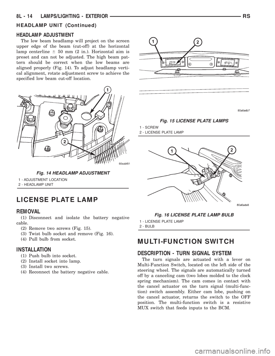
HEADLAMP ADJUSTMENT
The low beam headlamp will project on the screen
upper edge of the beam (cut-off) at the horizontal
lamp centerline650 mm (2 in.). Horizontal aim is
preset and can not be adjusted. The high beam pat-
tern should be correct when the low beams are
aligned properly (Fig. 14). To adjust headlamp verti-
cal alignment, rotate adjustment screw to achieve the
specified low beam cut-off location.
LICENSE PLATE LAMP
REMOVAL
(1) Disconnect and isolate the battery negative
cable.
(2) Remove two screws (Fig. 15).
(3) Twist bulb socket and remove (Fig. 16).
(4) Pull bulb from socket.
INSTALLATION
(1) Push bulb into socket.
(2) Install socket into lamp.
(3) Install two screws.
(4) Reconnect the battery negative cable.
MULTI-FUNCTION SWITCH
DESCRIPTION - TURN SIGNAL SYSTEM
The turn signals are actuated with a lever on
Multi-Function Switch, located on the left side of the
steering wheel. The signals are automatically turned
off by a canceling cam (two lobes molded to the clock
spring mechanism). The cam comes in contact with
the cancel actuator on the turn signal (multi-func-
tion) switch assembly. Either cam lobe, pushing on
the cancel actuator, returns the switch to the OFF
position. The multi-function switch is a resistive
MUX switch that feeds inputs to the BCM.
Fig. 14 HEADLAMP ADJUSTMENT
1 - ADJUSTMENT LOCATION
2 - HEADLAMP UNIT
Fig. 15 LICENSE PLATE LAMPS
1 - SCREW
2 - LICENSE PLATE LAMP
Fig. 16 LICENSE PLATE LAMP BULB
1 - LICENSE PLATE LAMP
2 - BULB
8L - 14 LAMPS/LIGHTING - EXTERIORRS
HEADLAMP UNIT (Continued)
Page 1972 of 4284
more faulty electronic modules in the vehicle, or from
a faulty PCI data bus. The use of a DRB IIItscan
tool and the proper Diagnostic Procedures manual
are required for further diagnosis.
NOTE: If the compass functions, but accuracy is
suspect, it may be necessary to perform a variation
adjustment. This procedure allows the compass
unit to accommodate variations in the earth's mag-
netic field strength, based on geographic location.
Refer to Compass Variation Adjustment in the Ser-
vice Procedures section of this group.
NOTE: If the compass reading displays dashes, and
only ªCALº appears in the display, demagnetizing
may be necessary to remove excessive residual
magnetic fields from the vehicle. Refer to Compass
Demagnetizing in the Service Procedures section of
this group.
STANDARD PROCEDURE - READING/
COURTESY LAMP REPLACEMENT
(1) Open hood, disconnect and isolate the negative
battery cable remote terminal from the remote bat-
tery post.
(2) Remove the reading/courtesy lamp lens. Using
a trim stick, gently pry the forward edge of the read-
ing/courtesy lamp lens outward.
(3) Remove the reading/courtesy lamp socket from
the overhead console. Rotate the reading/courtesy
lamp socket one quarter turn counter clockwise.
(4) Remove the lamp and socket assembly.
(5) Reverse the above procedure to install.
STANDARD PROCEDURE - COMPASS
CALIBRATION
CAUTION: Do not place any external magnets, such
as magnetic roof mount antennas, in the vicinity of
the compass. Do not use magnetic tools when ser-
vicing the overhead console.
The electronic compass unit features a self-cali-
brating design, which simplifies the calibration pro-
cedure. This feature automatically updates the
compass calibration while the vehicle is being driven.
This allows the compass unit to compensate for small
changes in the residual magnetism that the vehicle
may acquire during normal use. If the compass read-
ings appear to be erratic or out of calibration, per-
form the following calibration procedure. Also, new
service replacement Electronic Modules (EVIC,
CMTC, CT) must have their compass calibrated
using this procedure. Do not attempt to calibrate the
compass near large metal objects such as other vehi-cles, large buildings, or bridges; or, near overhead or
underground power lines.
NOTE: Whenever the compass is calibrated manu-
ally, the variance number must also be reset. Refer
to Compass Variation Adjustment in this group.
Calibrate the compass manually as follows:
(1) Turn the ignition switch to the On position. If
the compass/thermometer data is not currently being
displayed, momentarily depress and release the C/T
push button to reach the compass/thermometer dis-
play.
(2) On Electronic Vehicle Information Center
(EVIC) and Compass Mini-Trip Computer (CMTC)
equipped vehicles depress the Reset push button and
hold the button down until ªCALº appears in the dis-
play. This takes about ten seconds, and appears
about five seconds after ªVAR = XXº is displayed. On
Compass Temperature Module (CT) equipped vehicles
depress the C/T push button and US/M push button
down until ªCALº appears in the display. This takes
about ten seconds, and appears about five seconds
after ªVAR = XXº is displayed.
(3) Release the push button(s).
(4) Drive the vehicle on a level surface, away from
large metal objects and power lines, through three or
more complete circles at between five and eight kilo-
meters-per-hour (three and five miles-per-hour) in
not less than 48 seconds. The ªCALº message will
disappear from the display to indicate that the com-
pass is now calibrated.
NOTE: If the ªCALº message remains in the display,
either there is excessive magnetism near the com-
pass, or the unit is faulty. Repeat the calibration
procedure one more time.
NOTE: If the wrong direction is still indicated in the
compass display, the area selected for calibration
may be too close to a strong magnetic field. Repeat
the calibration procedure in another location.
STANDARD PROCEDURE - COMPASS
DEMAGNETIZING
A degaussing tool (Special Tool 6029) is used to
demagnetize, or degauss, the overhead console for-
ward mounting screw and the roof panel above the
overhead console. Equivalent units must be rated as
continuous duty for 110/115 volts and 60 Hz. They
must also have a field strength of over 350 gauss at 7
millimeters (0.25 inch) beyond the tip of the probe.
To demagnetize the roof panel and the overhead
console forward mounting screw, proceed as follows:
8M - 4 OVERHEAD CONSOLERS
OVERHEAD CONSOLE (Continued)
Page 2067 of 4284

(4) Connect vacuum line to speed control servo
that leads to the battery tray/vacuum reservoir.
(5) Install speed control servo and bracket.
(6) Install battery tray/vacuum reservoir, refer to
the Battery section for more information.
(7) Install speed control and throttle cable casing
to cable mount bracket.
(8) Connect the throttle and speed control cable
ends to throttle body.
(9) Connect the negative battery cable.
SWITCH
DESCRIPTION
There are two separate switch pods that operate
the speed control system and are located on the
steering wheel.
OPERATION
The speed control system has five separate resis-
tive switches that provide a single multiplexed
(MUX) voltage inputs to the PCM.The switch names
are: ON, OFF, SET, COAST, RESUME, ACCEL, TAP-
UP, COAST, and CANCEL. Based on conditions when
the buttons are pushed (and released), the five volt-
ages ranges provided to the PCM result in the follow-
ing functions: ON, OFF, SET, COAST, RESUME,
ACCEL, TAP-UP, COAST, and CANCEL. Refer to the
Speed Control Section for more information
Also the PCM receives an input from the brake
switch to sense whether the brake pedal has been
depressed. When the PCM receives the brake
depressed input, it turns off power to the speed con-
trol servo and disengages speed control.
The individual switches cannot be repaired. If one
switch fails, the entire switch module must be
replaced.
REMOVAL
The speed control switches are mounted in the
steering wheel and wired through the clock spring
device under the airbag module.
WARNING: IF REMOVAL OF AIRBAG MODULE IS
NECESSARY, REFER TO THE RESTRAINT SYS-
TEMS SECTION FOR MORE INFORMATION.
(1) Remove the negative battery cable.
(2) Turn off ignition.
(3) Remove the air bag, refer to the restraint sec-
tion for more information.
(4) Remove two screws from side of the switch.
(5) Remove switch from steering wheel.
(6) Disconnect two-way electrical connector.
(7) Repeat for the other switch.
INSTALLATION
The speed control switches are mounted in the
steering wheel and wired through the clock spring
device under the airbag module.
WARNING: IF REMOVAL OF AIRBAG MODULE IS
NECESSARY, REFER TO THE RESTRAINT SYS-
TEMS SECTION FOR MORE INFORMATION.
(1) Connect two-way electrical connector.
(2) Install switch.
Fig. 3 BATTERY TRAY/VACUUM RESERVOIR
Fig. 4 SPEED CONTROL SERVO
RSSPEED CONTROL8P-5
SERVO (Continued)
Page 2686 of 4284
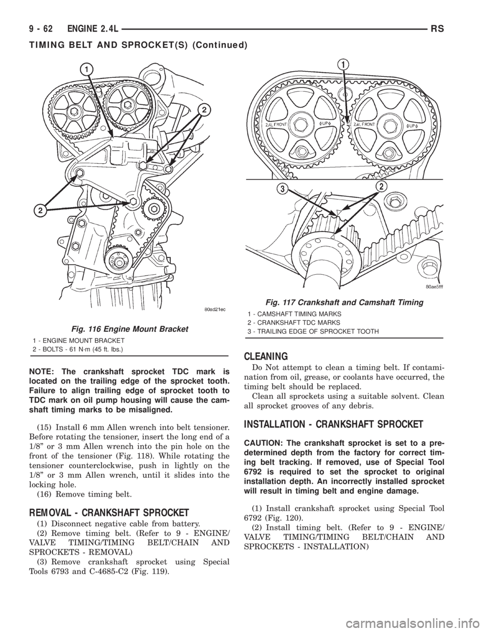
NOTE: The crankshaft sprocket TDC mark is
located on the trailing edge of the sprocket tooth.
Failure to align trailing edge of sprocket tooth to
TDC mark on oil pump housing will cause the cam-
shaft timing marks to be misaligned.
(15) Install 6 mm Allen wrench into belt tensioner.
Before rotating the tensioner, insert the long end of a
1/8º or 3 mm Allen wrench into the pin hole on the
front of the tensioner (Fig. 118). While rotating the
tensioner counterclockwise, push in lightly on the
1/8º or 3 mm Allen wrench, until it slides into the
locking hole.
(16) Remove timing belt.
REMOVAL - CRANKSHAFT SPROCKET
(1) Disconnect negative cable from battery.
(2) Remove timing belt. (Refer to 9 - ENGINE/
VALVE TIMING/TIMING BELT/CHAIN AND
SPROCKETS - REMOVAL)
(3) Remove crankshaft sprocket using Special
Tools 6793 and C-4685-C2 (Fig. 119).
CLEANING
Do Not attempt to clean a timing belt. If contami-
nation from oil, grease, or coolants have occurred, the
timing belt should be replaced.
Clean all sprockets using a suitable solvent. Clean
all sprocket grooves of any debris.
INSTALLATION - CRANKSHAFT SPROCKET
CAUTION: The crankshaft sprocket is set to a pre-
determined depth from the factory for correct tim-
ing belt tracking. If removed, use of Special Tool
6792 is required to set the sprocket to original
installation depth. An incorrectly installed sprocket
will result in timing belt and engine damage.
(1) Install crankshaft sprocket using Special Tool
6792 (Fig. 120).
(2) Install timing belt. (Refer to 9 - ENGINE/
VALVE TIMING/TIMING BELT/CHAIN AND
SPROCKETS - INSTALLATION)
Fig. 116 Engine Mount Bracket
1 - ENGINE MOUNT BRACKET
2 - BOLTS - 61 N´m (45 ft. lbs.)
Fig. 117 Crankshaft and Camshaft Timing
1 - CAMSHAFT TIMING MARKS
2 - CRANKSHAFT TDC MARKS
3 - TRAILING EDGE OF SPROCKET TOOTH
9 - 62 ENGINE 2.4LRS
TIMING BELT AND SPROCKET(S) (Continued)