brake sensor CHRYSLER VOYAGER 2001 Owner's Guide
[x] Cancel search | Manufacturer: CHRYSLER, Model Year: 2001, Model line: VOYAGER, Model: CHRYSLER VOYAGER 2001Pages: 4284, PDF Size: 83.53 MB
Page 1224 of 4284
A/C PRESSURE SENSOR CIRCUIT SIGNAL
VOLTAGE TOO HIGH
A/C PRESSURE SENSOR CIRCUIT SIGNAL
VOLTAGE TOO LOW
A/C PRESSURE SENSOR CIRCUIT SUPPLY
VOLTAGE TOO HIGH OR LOW
A/C PRESSURE SENSOR CIRCUIT PLAUSI-
BILITY
SYSTEM VOLTAGE TOO HIGH
SYSTEM VOLTAGE TOO LOW
S/C SWITCH SIGNAL CIRCUIT SIGNAL VOLT-
AGE TOO HIGH
S/C SWITCH SIGNAL CIRCUIT SIGNAL VOLT-
AGE TOO LOW
S/C SWITCH SIGNAL CIRCUIT PLAUSIBILITY
ECM ERROR RECOVERY HAS OCCURRED
ECM ERROR REDUNDANT OVERRUN MONI-
TORING
ECM ERROR GATE ARRAY - QUANTITY STOP
ECM ERROR GATE ARRAY - COMMUNICA-
TION
ECM ERROR - COMMUNICATION NOT VERI-
FIED
STARTER RELAY CIRCUIT OPEN CIRCUIT
STARTER RELAY CIRCUIT SHORT CIRCUIT
GENERATOR FIELD CONTROL MALF BAT-
TERY VOLTAGE TOO HIGH
GENERATOR FIELD CONTROL MALF BAT-
TERY VOLTAGE TOO LOW
GENERATOR FIELD CONTROL MALF OPEN
CIRCUIT
GENERATOR FIELD CONTROL MALF SHORT
CIRCUIT
GENERATOR FIELD CONTROL MALF
CHARGING VOLTS TOO LOW
GENERATOR FIELD CONTROL MALF BAT-
TERY VOLTAGE DEVIATION TOO HIGH
GENERATOR FIELD CONTROL MALF BAT-
TERY VOLTAGE DEVIATION TOO LOW
GENERATOR FIELD CONTROL MALF UN-
STABLE CURRENT
SENSOR REFERENCE VOLTAGE A CKT VOLT-
AGE TOO HIGH
SENSOR REFERENCE VOLTAGE A CKT VOLT-
AGE TOO LOW
SENSOR REFERENCE VOLTAGE B CKT
VOLTAGE TOO HIGH
SENSOR REFERENCE VOLTAGE B CKT
VOLTAGE TOO LOW
A/C CLUTCH RELAY CIRCUIT OPEN CIRCUIT
A/C CLUTCH RELAY CIRCUIT SHORT CIR-
CUIT
ECM/PCM RELAY CONTROL CIRCUIT SHUTS
OFF TOO EARLY
ECM/PCM RELAY CONTROL CIRCUIT SHUTS
OFF TOO LATE
BRAKE SWITCH SIGNAL CIRCUITS INCOR-
RECT CAN MESSAGEBRAKE SWITCH SIGNAL CIRCUITS PLAUSI-
BILITY WITH REDUNDANT CONTACT
BRAKE SWITCH SIGNAL CIRCUITS PLAUSI-
BILITY WITH REDUNDANT CONTACT AFTER
INITIALIZATION
CLUTCH UPSTOP SWITCH PERF PLAUSIBIL-
ITY
CLUTCH UPSTOP SWITCH PERF PLAUSIBIL-
ITY WITH P/N SWITCH
FUEL RAIL PRESSURE MALFUNCTION
PRESSURE TOO HIGH - LIMITATION
FUEL RAIL PRESSURE MALFUNCTION
PRESSURE TOO LOW
FUEL RAIL PRESSURE MALFUNCTION SO-
LENOID OPEN
FUEL RAIL PRESSURE MALFUNCTION
LEAKAGE DETECTED
FUEL PRESSURE SOLENOID OPEN CIRCUIT
FUEL PRESSURE SOLENOID SHORT CIR-
CUIT
FUEL PRESSURE SOLENOID PLAUSIBILITY
IN AFTER-RUN
CALCULATED INJECTOR VOLTAGE - VOLT-
AGE 1 TOO LOW
CALCULATED INJECTOR VOLTAGE - VOLT-
AGE 2 TOO LOW
BATTERY SENSE LINE 1 VOLTAGE TOO
HIGH
BATTERY SENSE LINE 1 VOLTAGE TOO LOW
FUEL PRESS REG CURRENT CONTROL SIG-
NAL TOO HIGH
FUEL PRESS REG CURRENT CONTROL SIG-
NAL TOO LOW
GENERATOR FIELD CURRENT TOO HIGH
GENERATOR FIELD CURRENT TOO LOW
CAPACITOR VOLTAGE 1 VOLTAGE TOO HIGH
CAPACITOR VOLTAGE 1 VOLTAGE TOO LOW
CAPACITOR VOLTAGE 2 VOLTAGE TOO HIGH
CAPACITOR VOLTAGE 2 VOLTAGE TOO LOW
IGNITION SWITCH PLAUSIBILITY
AFTER RUN SHUT OFF ERROR - ZERO
QUANTITY
AFTERRUN SHUT OFF ERROR - INJ. POWER-
STAGE
VOLTAGE REGULATOR SIGNAL VOLTAGE
TOO HIGH
VOLTAGE REGULATOR SIGNAL VOLTAGE
TOO LOW
MIL/DIAG LAMP VIA J1850 BUS IN FRAME
RESPONSE ERROR
MIL/DIAG LAMP VIA J1850 BUS - STATUS
ERROR
J1850 COMMUNICATION BUS SHORT TO
VOLTAGE
J1850 COMMUNICATION BUS SHORT TO
GROUND
J1850 COMMUNICATION BUS TRANSMIT
BUFFER OVERRUN
5
GENERAL INFORMATION
Page 1225 of 4284
J1850 COMMUNICATION BUS SPI ERROR
J1850 COMMUNICATION BUS RECEIVE TIME-
OUT
J1850 COMMUNICATION BUS UNAUTHO-
RIZED RESET
EEPROM PLAUSIBILITY CHECKSUM ERROR
EEPROM PLAUSIBILITY VIN CHECKSUM
ERROR
EEPROM PLAUSIBILITY COMMUNICATION
ERROR
EEPROM PLAUSIBILITY WRITE ERROR
EEPROM PLAUSIBILITY VARIATION NUM-
BER ERROR
EEPROM PLAUSIBILITY CODE WORD IN-
CORRECT OR MISSING
SKIM SYSTEM SKIM ERROR
SKIM SYSTEM WRITE ACCESS TO EEPROM
FAILURE
SKIM SYSTEM INVALID SECRET KEY IN EE-
PROM
SKIM SYSTEM KEY COMMUNICATION
TIMED OUT
SKIM SYSTEM INVALID KEY CODE RE-
CEIVED
EEPROM RECOVERY OCCURRED
EEPROM REDUNDANT OVERRUN MONI-
TORING
EEPROM QUANTITY STOP
EEPROM COMMUNICATION ERROR
EEPROM COMMUNICATION NOT VERIFIED
ACC PEDAL POSITION SENSOR 1 CKT SIG-
NAL VOLTAGE TOO HIGH
ACC PEDAL POSITION SENSOR 1 CKT SIG-
NAL VOLTAGE TOO LOW
ACC PEDAL POSITION SENSOR 1 CKT SUP-
PLY VOLTAGE TOO HIGH OR LOW
ACC PEDAL POSITION SENSOR 1 CKT PLAU-
SIBILITY WITH POTENTIOMETER
ACC PEDAL POSITION SENSOR 1 CKT PLAU-
SIBILITY WITH BRAKE SWITCH
ACC PEDAL POSITION SENSOR 1 CKT PLAU-
SIBILITY
3.3.4 SKIM DIAGNOSTIC TROUBLE CODES
ANTENNA FAILURE
COP FAILURE
EEPROM FAILURE
PCM STATUS FAILURE
INTERNAL FAULT
RAM FAILURE
ROLLING CODE FAILURE
SERIAL LINK EXTERNAL FAULT
SERIAL LINK INTERNAL FAULT
STACK OVERFLOW FAILURE
TRANSPONDER COMMUNICATION FAILURE
TRANSPONDER CRC (CYCLIC REDUN-
DANCY CHECK) FAILURE
TRANSPONDER ID MISMATCHTRANSPONDER RESPONSE MISMATCH
VIN MISMATCH
3.3.5 HANDLING NO TROUBLE CODE
PROBLEMS
After reading Section 3.0 (System Description
and Functional Operation), you should have a bet-
ter understanding of the theory and operation of the
on-board diagnostics, and how this relates to the
diagnosis of a vehicle that may have a driveability-
related symptom or complaint.
3.4 USING THE DRBIIIT
Refer to the DRBIIItuser 's guide for instructions
and assistance with reading the DTCs, erasing the
DTCs, lab scope usage and other DRBIIItfunc-
tions.
3.4.1 DRBIIITDOES NOT POWER UP
If the LEDs do not light or no sound is emitted at
start up, check for loose cable connections or a bad
cable. Check the vehicle battery voltage at data link
connector cavity 16. A minimum of 11.0 volts is
required to adequately power the DRB. Check for
proper ground connection at data link connector
cavities 4 and 5.
If all connections are proper between the
DRBIIItand the vehicle or other devices, and the
vehicle battery is fully charged, an inoperative
DRBIIItmay be the result of a faulty cable or
vehicle wiring. For a blank screen, refer to the
appropriate diagnostic manual.
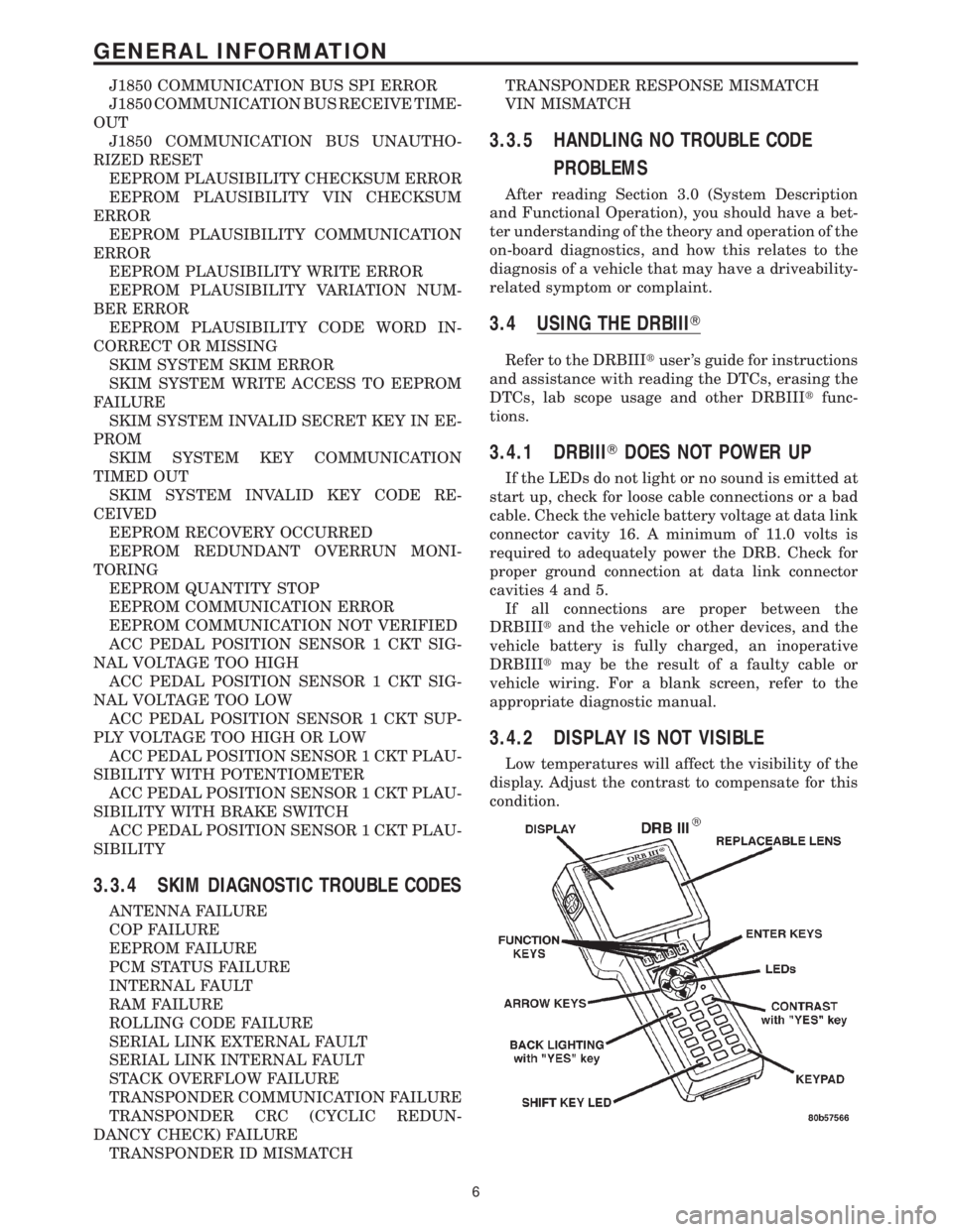
3.4.2 DISPLAY IS NOT VISIBLE
Low temperatures will affect the visibility of the
display. Adjust the contrast to compensate for this
condition.
6
GENERAL INFORMATION
Page 1389 of 4284
Symptom List:
P2120-ACC PEDAL POSITION SENSOR 1 CKT PLAUSIBILITY
P2120-ACC PEDAL POSITION SENSOR 1 CKT PLAUSIBILITY
WITH BRAKE SWITCH
P2120-ACC PEDAL POSITION SENSOR 1 CKT PLAUSIBILITY
WITH POTENTIOMETER
P2120-ACC PEDAL POSITION SENSOR 1 CKT SIGNAL VOLTAGE
TOO HIGH
P2120-ACC PEDAL POSITION SENSOR 1 CKT SIGNAL VOLTAGE
TOO LOW
P2120-ACC PEDAL POSITION SENSOR 1 CKT SUPPLY VOLTAGE
TOO HIGH OR LOW
Test Note: All symptoms listed above are diagnosed using the same tests.
The title for the tests will be P2120-ACC PEDAL POSITION
SENSOR 1 CKT PLAUSIBILITY.
When Monitored and Set Condition:
P2120-ACC PEDAL POSITION SENSOR 1 CKT PLAUSIBILITY
When Monitored: With the ignition on.
Set Condition: The Accelerator Pedal Position Sensor Signal is below 2% or above 21%
and the idle switch is not in the correct state. NOTE: The idle switch is designed to
transition when the accel position is approximately 16% (1.00 volt). This code sets the ECM
to Limp-in Mode, which includes a fixed engine speed of 1100 RPM.
P2120-ACC PEDAL POSITION SENSOR 1 CKT PLAUSIBILITY WITH BRAKE
SWITCH
When Monitored: With the ignition on.
Set Condition: The ECM detects the Accelerator Pedal and the Brake Pedal have been
depressed at the same time for longer than the allowable time.
P2120-ACC PEDAL POSITION SENSOR 1 CKT PLAUSIBILITY WITH POTENTI-
OMETER
When Monitored: With the ignition on.
Set Condition: The Accelerator Pedal Position Sensor Signal is below 0.20 volts, the idle
switch transitions at too high a percentage intermittently or the idle switch is not in the
correct state intermittently. NOTE: The idle switch is designed to transition when the accel
position is approximately 16% (1.00 volt). This code sets the ECM to Limp-in Mode, which
includes a fixed engine speed of 1100 RPM.
170
DRIVEABILITY - DIESEL
Page 1391 of 4284
POSSIBLE CAUSES
APP SENSOR GROUND CIRCUIT SHORTED TO VOLTAGE
LOW IDLE POSITION SWITCH SENSE CIRCUIT SHORTED TO VOLTAGE
LOW IDLE POSITION SWITCH SENSE GROUND CIRCUIT SHORTED TO VOLTAGE
VERIFY CORRECT SWITCHING
ECM - APP SENSOR SIGNAL CIRCUIT
TEST ACTION APPLICABILITY
1NOTE: The brake switch must be operational for the result of this test to be
valid.
Turn the ignition off.
Disconnect the APP Sensor harness connector.
Connect one end of a jumper wire to the Low Idle Position Sense circuit at the APP
Sensor harness connector.
Turn the ignition on.
With the DRB III, monitor the Low Idle Position Switch input while tapping the other
end of the jumper wire to the Sensor Ground circuit at the APP Sensor harness
connector.
Does the DRB III change between IDLE and ABOVE IDLE when tapping the jumper
wire?All
Ye s®Go To 2
No®Go To 20
2 Turn the ignition on.
With the DRB III observe the Low Idle Position Switch input.
Press and release the accelerator pedal several times while observing the DRB III
display.
NOTE: The Low Idle Position Switch input should change from IDLE to
ABOVE IDLE when pressing and releasing the accelerator pedal.
Did Low Idle Position Switch input change between IDLE and ABOVE IDLE?All
Ye s®Go To 3
No®Replace the Accelerator Pedal Position Sensor in accordance with
the Service Information.
Perform ROAD TEST VERIFICATION - VER-2.
3NOTE: If DTC P0641 or P0651 is present with this DTC, diagnose DTCs
P0641 and P0651 before diagnosing this DTC.
Turn the ignition off.
Disconnect the APP Sensor harness connector.
Turn the ignition on.
Measure the voltage of the 5-volt Supply circuit in APP Sensor harness connector.
Is the voltage between 4.7 and 5.3 volts?All
Ye s®Go To 4
No®Go To 16
172
DRIVEABILITY - DIESEL
P2120-ACC PEDAL POSITION SENSOR 1 CKT PLAUSIBILITY ÐContinued
Page 1413 of 4284
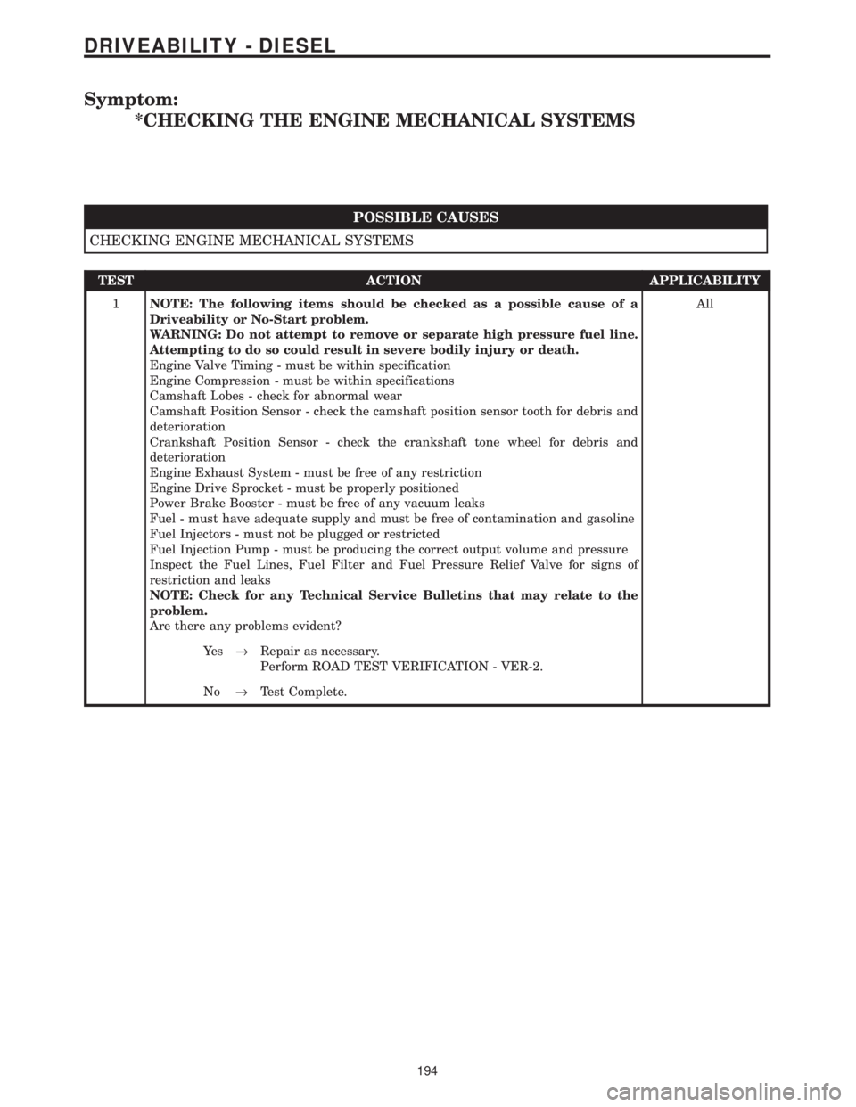
Symptom:
*CHECKING THE ENGINE MECHANICAL SYSTEMS
POSSIBLE CAUSES
CHECKING ENGINE MECHANICAL SYSTEMS
TEST ACTION APPLICABILITY
1NOTE: The following items should be checked as a possible cause of a
Driveability or No-Start problem.
WARNING: Do not attempt to remove or separate high pressure fuel line.
Attempting to do so could result in severe bodily injury or death.
Engine Valve Timing - must be within specification
Engine Compression - must be within specifications
Camshaft Lobes - check for abnormal wear
Camshaft Position Sensor - check the camshaft position sensor tooth for debris and
deterioration
Crankshaft Position Sensor - check the crankshaft tone wheel for debris and
deterioration
Engine Exhaust System - must be free of any restriction
Engine Drive Sprocket - must be properly positioned
Power Brake Booster - must be free of any vacuum leaks
Fuel - must have adequate supply and must be free of contamination and gasoline
Fuel Injectors - must not be plugged or restricted
Fuel Injection Pump - must be producing the correct output volume and pressure
Inspect the Fuel Lines, Fuel Filter and Fuel Pressure Relief Valve for signs of
restriction and leaks
NOTE: Check for any Technical Service Bulletins that may relate to the
problem.
Are there any problems evident?All
Ye s®Repair as necessary.
Perform ROAD TEST VERIFICATION - VER-2.
No®Test Complete.
194
DRIVEABILITY - DIESEL
Page 1419 of 4284
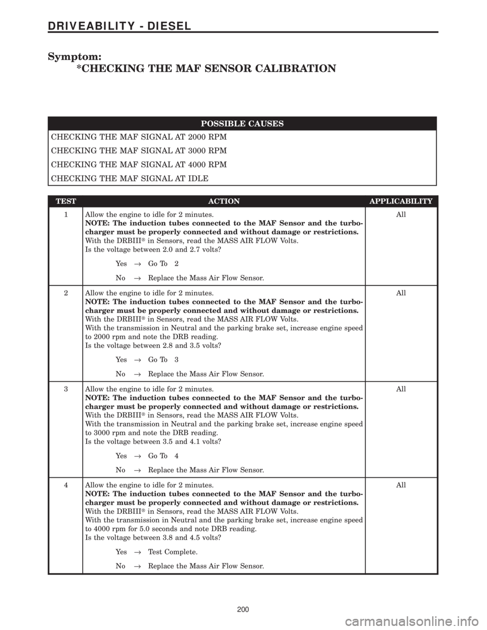
Symptom:
*CHECKING THE MAF SENSOR CALIBRATION
POSSIBLE CAUSES
CHECKING THE MAF SIGNAL AT 2000 RPM
CHECKING THE MAF SIGNAL AT 3000 RPM
CHECKING THE MAF SIGNAL AT 4000 RPM
CHECKING THE MAF SIGNAL AT IDLE
TEST ACTION APPLICABILITY
1 Allow the engine to idle for 2 minutes.
NOTE: The induction tubes connected to the MAF Sensor and the turbo-
charger must be properly connected and without damage or restrictions.
With the DRBIIItin Sensors, read the MASS AIR FLOW Volts.
Is the voltage between 2.0 and 2.7 volts?All
Ye s®Go To 2
No®Replace the Mass Air Flow Sensor.
2 Allow the engine to idle for 2 minutes.
NOTE: The induction tubes connected to the MAF Sensor and the turbo-
charger must be properly connected and without damage or restrictions.
With the DRBIIItin Sensors, read the MASS AIR FLOW Volts.
With the transmission in Neutral and the parking brake set, increase engine speed
to 2000 rpm and note the DRB reading.
Is the voltage between 2.8 and 3.5 volts?All
Ye s®Go To 3
No®Replace the Mass Air Flow Sensor.
3 Allow the engine to idle for 2 minutes.
NOTE: The induction tubes connected to the MAF Sensor and the turbo-
charger must be properly connected and without damage or restrictions.
With the DRBIIItin Sensors, read the MASS AIR FLOW Volts.
With the transmission in Neutral and the parking brake set, increase engine speed
to 3000 rpm and note the DRB reading.
Is the voltage between 3.5 and 4.1 volts?All
Ye s®Go To 4
No®Replace the Mass Air Flow Sensor.
4 Allow the engine to idle for 2 minutes.
NOTE: The induction tubes connected to the MAF Sensor and the turbo-
charger must be properly connected and without damage or restrictions.
With the DRBIIItin Sensors, read the MASS AIR FLOW Volts.
With the transmission in Neutral and the parking brake set, increase engine speed
to 4000 rpm for 5.0 seconds and note DRB reading.
Is the voltage between 3.8 and 4.5 volts?All
Ye s®Test Complete.
No®Replace the Mass Air Flow Sensor.
200
DRIVEABILITY - DIESEL
Page 1421 of 4284
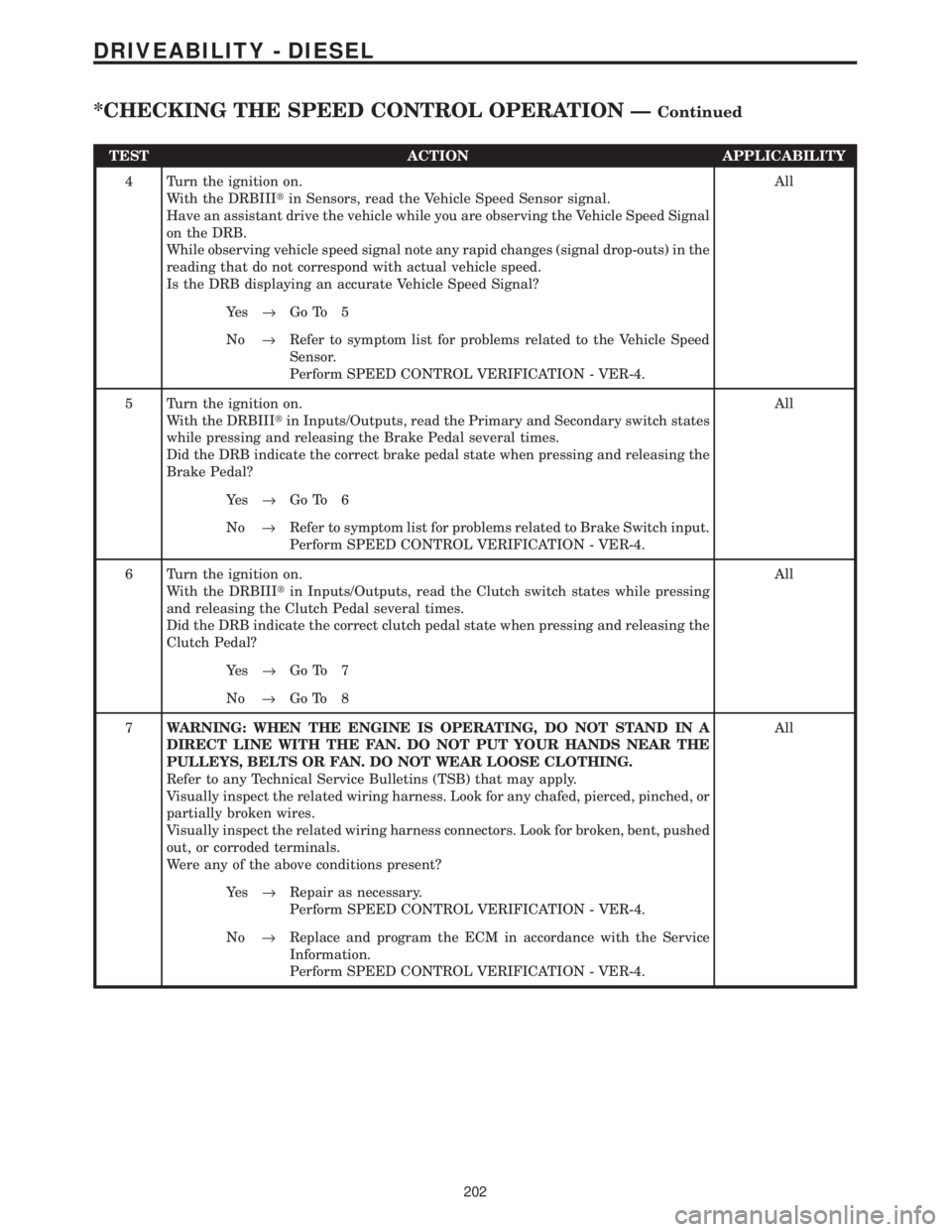
TEST ACTION APPLICABILITY
4 Turn the ignition on.
With the DRBIIItin Sensors, read the Vehicle Speed Sensor signal.
Have an assistant drive the vehicle while you are observing the Vehicle Speed Signal
on the DRB.
While observing vehicle speed signal note any rapid changes (signal drop-outs) in the
reading that do not correspond with actual vehicle speed.
Is the DRB displaying an accurate Vehicle Speed Signal?All
Ye s®Go To 5
No®Refer to symptom list for problems related to the Vehicle Speed
Sensor.
Perform SPEED CONTROL VERIFICATION - VER-4.
5 Turn the ignition on.
With the DRBIIItin Inputs/Outputs, read the Primary and Secondary switch states
while pressing and releasing the Brake Pedal several times.
Did the DRB indicate the correct brake pedal state when pressing and releasing the
Brake Pedal?All
Ye s®Go To 6
No®Refer to symptom list for problems related to Brake Switch input.
Perform SPEED CONTROL VERIFICATION - VER-4.
6 Turn the ignition on.
With the DRBIIItin Inputs/Outputs, read the Clutch switch states while pressing
and releasing the Clutch Pedal several times.
Did the DRB indicate the correct clutch pedal state when pressing and releasing the
Clutch Pedal?All
Ye s®Go To 7
No®Go To 8
7WARNING: WHEN THE ENGINE IS OPERATING, DO NOT STAND IN A
DIRECT LINE WITH THE FAN. DO NOT PUT YOUR HANDS NEAR THE
PULLEYS, BELTS OR FAN. DO NOT WEAR LOOSE CLOTHING.
Refer to any Technical Service Bulletins (TSB) that may apply.
Visually inspect the related wiring harness. Look for any chafed, pierced, pinched, or
partially broken wires.
Visually inspect the related wiring harness connectors. Look for broken, bent, pushed
out, or corroded terminals.
Were any of the above conditions present?All
Ye s®Repair as necessary.
Perform SPEED CONTROL VERIFICATION - VER-4.
No®Replace and program the ECM in accordance with the Service
Information.
Perform SPEED CONTROL VERIFICATION - VER-4.
202
DRIVEABILITY - DIESEL
*CHECKING THE SPEED CONTROL OPERATION ÐContinued
Page 1451 of 4284
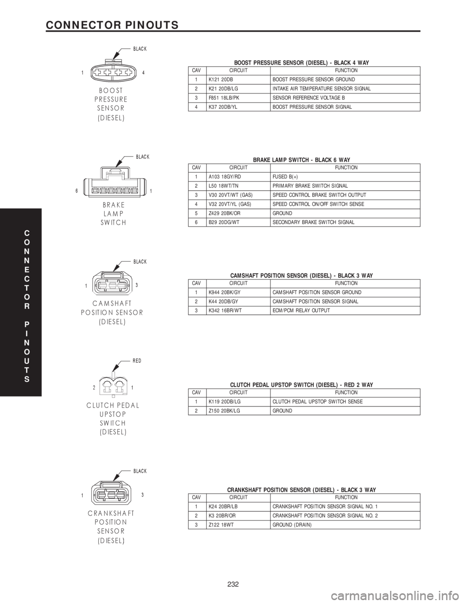
BOOST PRESSURE SENSOR (DIESEL) - BLACK 4 WAYCAV CIRCUIT FUNCTION
1 K121 20DB BOOST PRESSURE SENSOR GROUND
2 K21 20DB/LG INTAKE AIR TEMPERATURE SENSOR SIGNAL
3 F851 18LB/PK SENSOR REFERENCE VOLTAGE B
4 K37 20DB/YL BOOST PRESSURE SENSOR SIGNAL
BRAKE LAMP SWITCH - BLACK 6 WAYCAV CIRCUIT FUNCTION
1 A103 18GY/RD FUSED B(+)
2 L50 18WT/TN PRIMARY BRAKE SWITCH SIGNAL
3 V30 20VT/WT (GAS) SPEED CONTROL BRAKE SWITCH OUTPUT
4 V32 20VT/YL (GAS) SPEED CONTROL ON/OFF SWITCH SENSE
5 Z429 20BK/OR GROUND
6 B29 20DG/WT SECONDARY BRAKE SWITCH SIGNAL
CAMSHAFT POSITION SENSOR (DIESEL) - BLACK 3 WAYCAV CIRCUIT FUNCTION
1 K944 20BK/GY CAMSHAFT POSITION SENSOR GROUND
2 K44 20DB/GY CAMSHAFT POSITION SENSOR SIGNAL
3 K342 16BR/WT ECM/PCM RELAY OUTPUT
CLUTCH PEDAL UPSTOP SWITCH (DIESEL) - RED 2 WAYCAV CIRCUIT FUNCTION
1 K119 20DB/LG CLUTCH PEDAL UPSTOP SWITCH SENSE
2 Z150 20BK/LG GROUND
CRANKSHAFT POSITION SENSOR (DIESEL) - BLACK 3 WAYCAV CIRCUIT FUNCTION
1 K24 20BR/LB CRANKSHAFT POSITION SENSOR SIGNAL NO. 1
2 K3 20BR/OR CRANKSHAFT POSITION SENSOR SIGNAL NO. 2
3 Z122 18WT GROUND (DRAIN)
C
O
N
N
E
C
T
O
R
P
I
N
O
U
T
S
232
CONNECTOR PINOUTS
Page 1453 of 4284
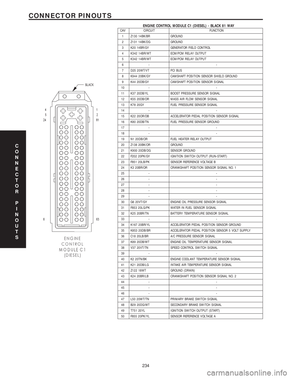
ENGINE CONTROL MODULE C1 (DIESEL) - BLACK 81 WAYCAV CIRCUIT FUNCTION
1 Z130 14BK/BR GROUND
2 Z131 14BK/DG GROUND
3 K20 14BR/GY GENERATOR FIELD CONTROL
4 K342 14BR/WT ECM/PCM RELAY OUTPUT
5 K342 14BR/WT ECM/PCM RELAY OUTPUT
6- -
7 D25 20WT/VT PCI BUS
8 K944 20BK/GY CAMSHAFT POSITION SENSOR SHIELD GROUND
9 K44 20DB/GY CAMSHAFT POSITION SENSOR SIGNAL
10 - -
11 K37 20DB/YL BOOST PRESSURE SENSOR SIGNAL
12 K55 20DB/OR MASS AIR FLOW SENSOR SIGNAL
13 K78 20GY FUEL PRESSURE SENSOR SIGNAL
14 - -
15 K22 20OR/DB ACCELERATOR PEDAL POSITION SENSOR SIGNAL
16 K80 20DB/TN FUEL PRESSURE SENSOR GROUND
17 - -
18 - -
19 N1 20DB/OR FUEL HEATER RELAY OUTPUT
20 Z138 20BK/OR GROUND
21 K900 20DB/DG SENSOR GROUND
22 F202 20PK/GY IGNITION SWITCH OUTPUT (RUN-START)
23 F851 20LB/PK SENSOR REFERENCE VOLTAGE B
24 K3 20BR/OR CRANKSHAFT POSITION SENSOR SIGNAL NO. 1
25 - -
26 - -
27 - -
28 - -
29 - -
30 G6 20VT/GY ENGINE OIL PRESSURE SENSOR SIGNAL
31 F853 20LG/PK WATER IN FUEL SENSOR SIGNAL
32 K25 20BR/TN BATTERY TEMPERATURE SENSOR SIGNAL
33 - -
34 K167 20BR/YL ACCELERATOR PEDAL POSITION SENSOR GROUND
35 K853 20DB/BR ACCELERATOR PEDAL POSITION SENSOR 5 VOLT SUPPLY
36 C18 20LB/BR A/C PRESSURE SENSOR SIGNAL
37 K89 20DB/WT ENGINE OIL TEMPERATURE SENSOR SIGNAL
38 V37 20VT/TN SPEED CONTROL SWITCH SIGNAL
39 - -
40 K2 20TN/BK ENGINE COOLANT TEMPERATURE SENSOR SIGNAL
41 K21 20DB/LG INTAKE AIR TEMPERATURE SENSOR SIGNAL
42 Z122 18WT GROUND (DRAIN)
43 K24 20BR/LB CRANKSHAFT POSITION SENSOR SIGNAL NO. 2
44 - -
45 - -
46 - -
47 L50 20WT/TN PRIMARY BRAKE SWITCH SIGNAL
48 B29 20DG/WT SECONDARY BRAKE SWITCH SIGNAL
49 T751 20YL IGNITION SWITCH OUTPUT (START)
50 F855 20PK/YL SENSOR REFERENCE VOLTAGE A
C
O
N
N
E
C
T
O
R
P
I
N
O
U
T
S
234
CONNECTOR PINOUTS
Page 1523 of 4284
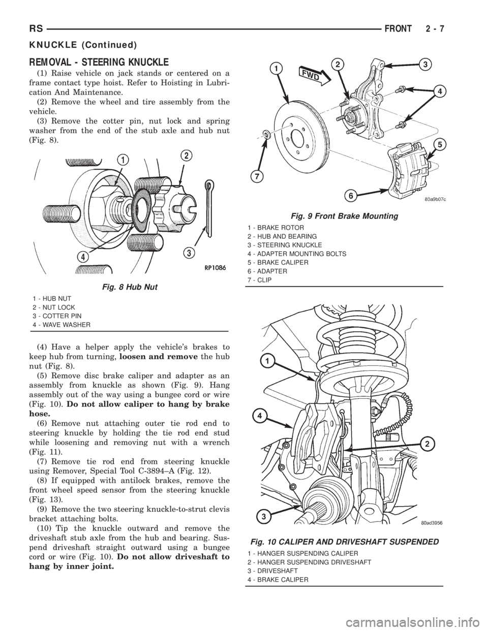
REMOVAL - STEERING KNUCKLE
(1) Raise vehicle on jack stands or centered on a
frame contact type hoist. Refer to Hoisting in Lubri-
cation And Maintenance.
(2) Remove the wheel and tire assembly from the
vehicle.
(3) Remove the cotter pin, nut lock and spring
washer from the end of the stub axle and hub nut
(Fig. 8).
(4) Have a helper apply the vehicle's brakes to
keep hub from turning,loosen and removethe hub
nut (Fig. 8).
(5) Remove disc brake caliper and adapter as an
assembly from knuckle as shown (Fig. 9). Hang
assembly out of the way using a bungee cord or wire
(Fig. 10).Do not allow caliper to hang by brake
hose.
(6) Remove nut attaching outer tie rod end to
steering knuckle by holding the tie rod end stud
while loosening and removing nut with a wrench
(Fig. 11).
(7) Remove tie rod end from steering knuckle
using Remover, Special Tool C-3894±A (Fig. 12).
(8) If equipped with antilock brakes, remove the
front wheel speed sensor from the steering knuckle
(Fig. 13).
(9) Remove the two steering knuckle-to-strut clevis
bracket attaching bolts.
(10) Tip the knuckle outward and remove the
driveshaft stub axle from the hub and bearing. Sus-
pend driveshaft straight outward using a bungee
cord or wire (Fig. 10).Do not allow driveshaft to
hang by inner joint.
Fig. 8 Hub Nut
1 - HUB NUT
2 - NUT LOCK
3 - COTTER PIN
4 - WAVE WASHER
Fig. 9 Front Brake Mounting
1 - BRAKE ROTOR
2 - HUB AND BEARING
3 - STEERING KNUCKLE
4 - ADAPTER MOUNTING BOLTS
5 - BRAKE CALIPER
6 - ADAPTER
7 - CLIP
Fig. 10 CALIPER AND DRIVESHAFT SUSPENDED
1 - HANGER SUSPENDING CALIPER
2 - HANGER SUSPENDING DRIVESHAFT
3 - DRIVESHAFT
4 - BRAKE CALIPER
RSFRONT2-7
KNUCKLE (Continued)