open hood CHRYSLER VOYAGER 2001 Owner's Guide
[x] Cancel search | Manufacturer: CHRYSLER, Model Year: 2001, Model line: VOYAGER, Model: CHRYSLER VOYAGER 2001Pages: 4284, PDF Size: 83.53 MB
Page 3570 of 4284

COWL GRILLE
REMOVAL
(1) Remove wiper arms. (Refer to 8 - ELECTRI-
CAL/WIPERS/WASHERS/WIPER ARMS -
REMOVAL)
(2) Remove four (4) screws securing cowel to wiper
module (Fig. 6).
(3) Disengage quarter turn fasteners at outboard
ends of cowl grill from body.
(4) Release hood latch and open hood.
CAUTION: To prevent hood scratching of cowl grille
before removal, cover outboard exterior ends of
cowl grille with masking tape or equivalent method.
NOTE: Do not over bend cowl grille during removal.
Bend cowl grille just enough to clear top of wiper
pivot shaft and bottom rear corner of hood.
(5) Remove cowl grill by raising above driver side
wiper pivot shaft and swinging away towards engine
compartment. the cowl grille will need to be bent on
outboard end to clear simultaneoudly top of wiper
pivot shaft and bottom corner of hood.
(6) Close hood. Do not latch. Remove outboard
screws. (Fig. 7).
(7) Disconnect washer hose in-line connector.
(8) Disconnect washer hose and grommet from
hole in wiper module and pull out.
(9) Remove cowl grille by raising over opposite
wiper pivot shaft and removing away from vehicle.
(10) Remove cowl cover from vehicle.
INSTALLATION
(1) Reverse removal procedure.
(2) When installing cowel grille over wiper module,
make sure fore-aft locator on the underside of cowl
grill seat into the locator grooves on top of wiper
module.
(3) Star all cowl grille mounting screws by hand
before torquing to specifications.
(4) Assure washer hose is properly routed and not
pinched.
(5) Center cowl grille to body and windshield.
(6) Assure ªarrowº indicator head of quarter turn
fasteners is pointing toward winshield.
(7) Screw torque1.2 n.m (11 in. lb.)
(8) Install the wiper arms. (Refer to 8 - ELECTRI-
CAL/WIPERS/WASHERS/WIPER ARMS - INSTAL-
LATION)
(9) Check for proper spray pattern from washer
nozzles.
Fig. 6 Cowl Cover
1 - COWL COVER
2 - WIPER PIVOT
3 - WASHER HOSES
4 - HOOD
Fig. 7 Cowl Cover Retainers
1 - SCREW
2 - WINDSHIELD
3 - COWL COVER
4 - FRONT FENDER
23 - 190 EXTERIORRS
Page 3574 of 4284

(5) Install fuel filler housing to outer quarter
panel.
(6) Verify that all clips on fuel filler housing are
fully engaged to outer quarter panel.
(7) Engage fuel filler lockout link into clip on fuel
fill blocker latch arm.
(8) Install water shield patch covering access hole
in C-pillar.
(9) Install left quarter trim panel.
GRILLE OPENING
REINFORCEMENT
REMOVAL
(1) Release hood latch and open hood.
(2) Remove bolts attaching hood latch to cross-
member and position latch out of the way.
(3) Remove radiator sight shield.
(4) Remove engine air inlet resonator.
(5) Remove hood cable.
(6) Remove hood prop rod.
(7) Remove screw attaching coolant recovery bottle
to crossmember.
(8) Remove bolts attaching radiator isolators to
crossmember.
(9) Remove bolts attaching ends of crossmember to
radiator closure panel (Fig. 14) .
(10) Lift crossmember upward and away from
radiator closure panel.
(11) Remove crossmember from vehicle.
INSTALLATION
(1) Place radiator closure panel crossmember in
position on vehicle.
(2) Insert ends of crossmember between layered
metal sections of radiator closure panel at each side
of radiator.
(3) Align with paint breaks around bolt heads.
(4) Install bolts attaching ends of crossmember to
radiator closure panel (Fig. 14) . Tighten bolts to 19
N´m (14 ft. lbs.) torque.
(5) Install bolts attaching radiator isolators to
crossmember.
(6) Install screw attaching coolant recovery bottle
to crossmember.
(7) Install bolt attaching air cleaner housing to
crossmember.
(8) Install engine air inlet resonator.
(9) Install radiator sight shield.
(10) Install hood prop rod.
(11) Align hood latch by placing latch over net
pierce tabs. If alignment is required, flatten tabs.
(12) Install bolts attaching hood latch to cross-
member. Tighten bolts to 13.5 N´m (10 ft. lbs.)
torque.
(13) Verify hood latch operation and hood align-
ment.
FRONT WHEELHOUSE
SPLASH SHIELD
REMOVAL
(1) Hoist and support vehicle on safety stands.
(Refer to LUBRICATION & MAINTENANCE/HOIST-
ING - STANDARD PROCEDURE)
(2) Remove front wheel. Refer to section 22, Tires/
Wheels, for recommended procedures.
(3) Remove push-in fasteners holding splash shield
to frame rail forward of suspension.
(4) Remove push-in fasteners holding splash shield
to frame rail rearward of suspension.
(5) Remove screws holding wheelhouse splash
shield to front fender.
(6) Remove splash shield from vehicle (Fig. 15).
Fig. 14 Radiator Closure Panel Crossmember
1 - RADIATOR CLOSURE PANEL CROSSMEMBER
2 - FRONT FASCIA
23 - 194 EXTERIORRS
FUEL FILL DOOR BLOCKER LOCKOUT LINK (Continued)
Page 3580 of 4284
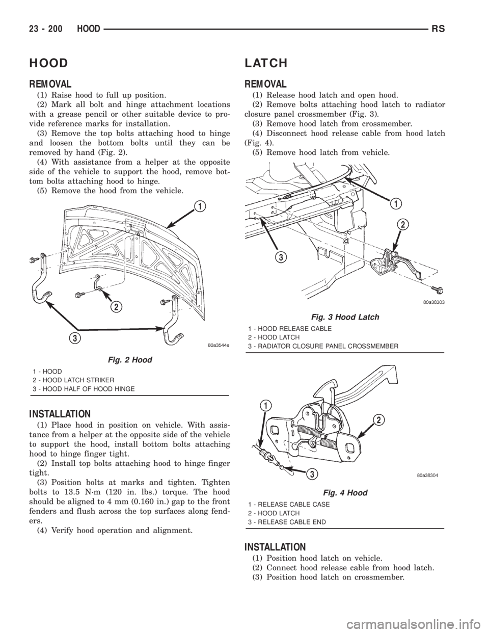
HOOD
REMOVAL
(1) Raise hood to full up position.
(2) Mark all bolt and hinge attachment locations
with a grease pencil or other suitable device to pro-
vide reference marks for installation.
(3) Remove the top bolts attaching hood to hinge
and loosen the bottom bolts until they can be
removed by hand (Fig. 2).
(4) With assistance from a helper at the opposite
side of the vehicle to support the hood, remove bot-
tom bolts attaching hood to hinge.
(5) Remove the hood from the vehicle.
INSTALLATION
(1) Place hood in position on vehicle. With assis-
tance from a helper at the opposite side of the vehicle
to support the hood, install bottom bolts attaching
hood to hinge finger tight.
(2) Install top bolts attaching hood to hinge finger
tight.
(3) Position bolts at marks and tighten. Tighten
bolts to 13.5 N´m (120 in. lbs.) torque. The hood
should be aligned to 4 mm (0.160 in.) gap to the front
fenders and flush across the top surfaces along fend-
ers.
(4) Verify hood operation and alignment.
LATCH
REMOVAL
(1) Release hood latch and open hood.
(2) Remove bolts attaching hood latch to radiator
closure panel crossmember (Fig. 3).
(3) Remove hood latch from crossmember.
(4) Disconnect hood release cable from hood latch
(Fig. 4).
(5) Remove hood latch from vehicle.
INSTALLATION
(1) Position hood latch on vehicle.
(2) Connect hood release cable from hood latch.
(3) Position hood latch on crossmember.
Fig. 2 Hood
1 - HOOD
2 - HOOD LATCH STRIKER
3 - HOOD HALF OF HOOD HINGE
Fig. 3 Hood Latch
1 - HOOD RELEASE CABLE
2 - HOOD LATCH
3 - RADIATOR CLOSURE PANEL CROSSMEMBER
Fig. 4 Hood
1 - RELEASE CABLE CASE
2 - HOOD LATCH
3 - RELEASE CABLE END
23 - 200 HOODRS
Page 3581 of 4284
(4) Align hood latch by placing latch over net
pierced tabs. If alignment is required, flatten or
grind tabs.
(5) Verify hood operation and alignment. Adjust as
necessary.
(6) Tighten attaching bolts to 13.5 N´m (10 ft. lbs.)
torque.
LATCH RELEASE CABLE
REMOVAL
(1) Remove hood latch.
(2) Disengage cable end from hood latch locking
mechanism.
(3) Slide cable case end sideways in keyhole slot of
hood latch while pinching barb on cable case closed.
(4) Remove cable from latch (Fig. 4).
(5) Remove hood release handle from instrument
panel.
(6) Disengage rubber grommet cable insulator
from hole in dash panel.
(7) Attach a suitable length of mechanic's wire to
latch end of cable to assist cable installation.
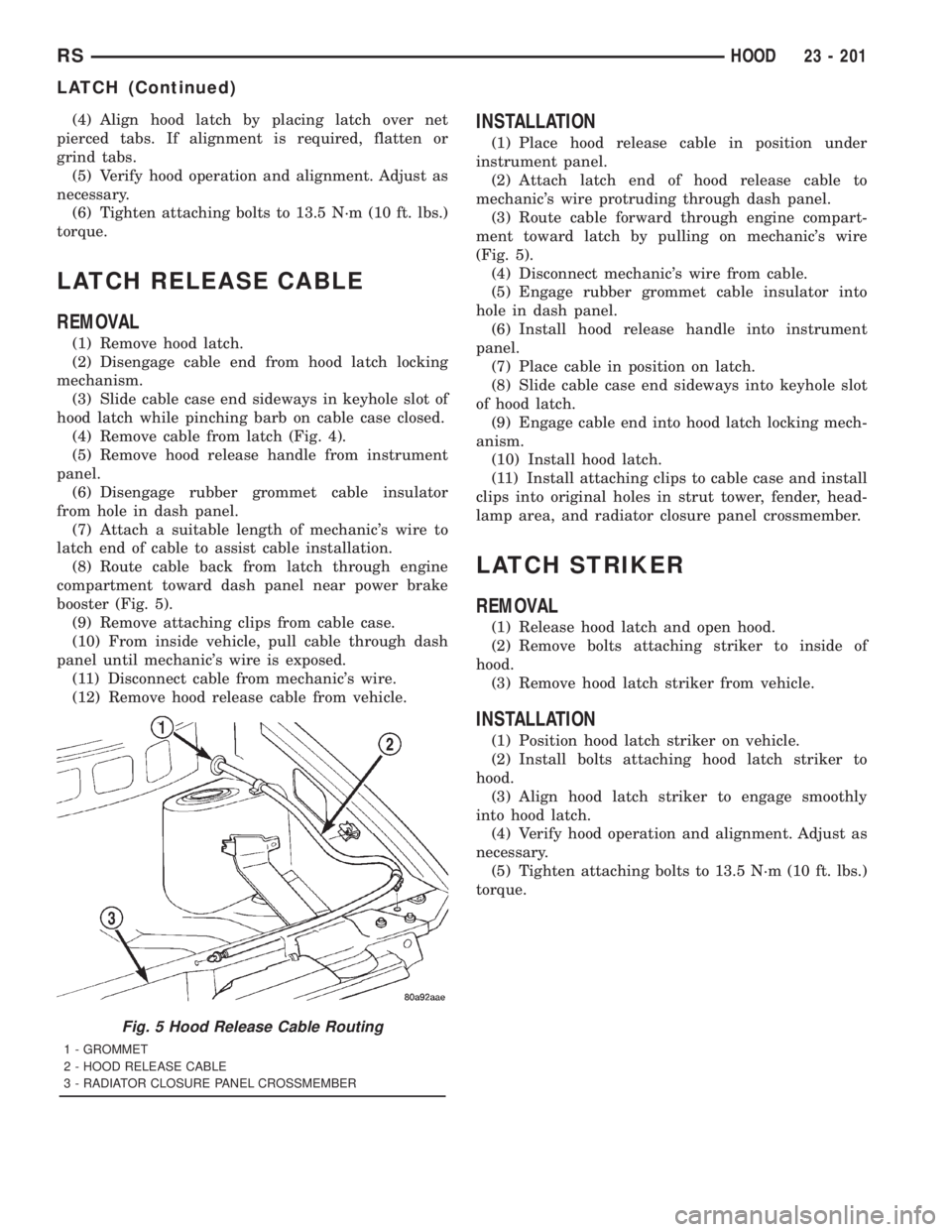
(8) Route cable back from latch through engine
compartment toward dash panel near power brake
booster (Fig. 5).
(9) Remove attaching clips from cable case.
(10) From inside vehicle, pull cable through dash
panel until mechanic's wire is exposed.
(11) Disconnect cable from mechanic's wire.
(12) Remove hood release cable from vehicle.
INSTALLATION
(1) Place hood release cable in position under
instrument panel.
(2) Attach latch end of hood release cable to
mechanic's wire protruding through dash panel.
(3) Route cable forward through engine compart-
ment toward latch by pulling on mechanic's wire
(Fig. 5).
(4) Disconnect mechanic's wire from cable.
(5) Engage rubber grommet cable insulator into
hole in dash panel.
(6) Install hood release handle into instrument
panel.
(7) Place cable in position on latch.
(8) Slide cable case end sideways into keyhole slot
of hood latch.
(9) Engage cable end into hood latch locking mech-
anism.
(10) Install hood latch.
(11) Install attaching clips to cable case and install
clips into original holes in strut tower, fender, head-
lamp area, and radiator closure panel crossmember.
LATCH STRIKER
REMOVAL
(1) Release hood latch and open hood.
(2) Remove bolts attaching striker to inside of
hood.
(3) Remove hood latch striker from vehicle.
INSTALLATION
(1) Position hood latch striker on vehicle.
(2) Install bolts attaching hood latch striker to
hood.
(3) Align hood latch striker to engage smoothly
into hood latch.
(4) Verify hood operation and alignment. Adjust as
necessary.
(5) Tighten attaching bolts to 13.5 N´m (10 ft. lbs.)
torque.
Fig. 5 Hood Release Cable Routing
1 - GROMMET
2 - HOOD RELEASE CABLE
3 - RADIATOR CLOSURE PANEL CROSSMEMBER
RSHOOD23 - 201
LATCH (Continued)
Page 3583 of 4284
(5) Install the cup holder. Align the cup holder
assembly with the track and firmly slide shut to
engage retaining tang.
GLOVE BOX
REMOVAL
(1) Open glove box.
(2) Push in on sides of glove box bin and lower
door.
(3) Pivot glove box downward and disengage hinge
hooks from instrument panel.
(4) Remove glove box.
INSTALLATION
(1) Place glove box in position.
(2) Engage hinge hooks into instrument panel and
pivot glove box upward.
(3) Push in sides of glove box bin and snap glove
box assembly into instrument panel.
(4) Close glove box door.
GLOVE BOX LATCH
REMOVAL
(1) Open glove box.
(2) Push in on sides of glove box bin and lower
door.
(3) Pivot glove box downward and disengage hinge
hooks from instrument panel.
(4) Remove glove box.
(5) Remove the assembly screws.
(6) Disassemble the glove box.
(7) Separate the latch from the glove box assembly.
INSTALLATION
(1) Install the latch onto the glove box assembly.
(2) Assemble the glove box.
(3) Install the assembly screws.
(4) Engage hinge hooks into instrument panel and
pivot glove box upward.
(5) Push in sides of glove box bin and snap glove
box assembly into instrument panel.
(6) Close glove box door.
GLOVE BOX LATCH STRIKER
REMOVAL
(1) Open glove box door.
(2) Remove screws holding lock striker to instru-
ment panel.
(3) Remove glove box latch striker.
INSTALLATION
(1) Install the glove box latch striker.
(2) Install the screws holding latch striker to
instrument panel.
(3) Close glove box door.
INSTRUMENT PANEL
ASSEMBLY
REMOVAL
(1) Disconnect and isolate the battery negative
cable.
(2) Remove the lower console:
(a) Remove six retaining screws.
(b) Pull rearward and disconnect the auxiliary
power outlet.
(c) Remove lower console from vehicle.
(3) Remove the bolts holding the lower supports to
the instrument panel frame.
(4) Remove the bolts holding the lower supports to
the floor pan.
(5) Disconnect the wire connectors from the Pas-
senger Airbag.
(6) Remove the two screws to each right and left
cowl trim covers.
(7) Remove the both left and right side A-pillar
trim covers using a trim stick (special tool #C-4755)
or equivalent gently pry out on the trim covers and
remove.
(8) Remove the glove box:
(a) Push in on sides of glove box bin and lower
door.
(b) Pivot glove box downward and disengage
hinge hooks from instrument panel.
(c) Remove glove box from vehicle.
(9) Disconnect the antenna lead connector from
behind the glove box.
(10) Remove the four screws to the lower steering
column cover.
(11) Remove the eight screws to the plastic knee
blocker reinforcement.
(12) Unclip the Data Link Connector (DLC) from
the instrument panel reinforcement.
(13) Remove one screw to the left side instrument
panel silencer and remove.
(14) Disconnect the left side wiring:
(a) Brake switch.
(b) Main bulkhead connector.
(c) Five harness connectors.
(d) Driver airbag connector.
(15) Remove the two screws to the hood release
handle.
(16) Remove five screws to the left under column
instrument panel reinforcement brace and remove.
RSINSTRUMENT PANEL23 - 203
CUP HOLDER (Continued)
Page 3585 of 4284
(20) Install the two screws to the hood release
handle.
(21) Connect the left side wiring:
(a) Brake switch.
(b) Main bulkhead connector.
(c) Five harness connectors.
(d) Driver airbag connector.
(22) Install one screw to the left side instrument
panel silencer.
(23) Clip the Data Link Connector (DLC) to the
instrument panel reinforcement.
(24) Install the eight screws to the plastic knee
blocker reinforcement.
(25) Install the four screws to the lower steering
column cover.
(26) Install the glove box:
(a) Install glove box into the vehicle. Line up the
hinges and firmly snap together.
(b) Push in on sides of glove box bin and raise
door.
(27) Install the both left and right side A-pillar
trim covers. Position trim cover over slots and firmly
snap into place.
(28) Install the two screws to each right and left
cowl trim covers.
(29) Connect the wire connectors to the Passenger
Airbag.
(30) Install the bolts holding the lower supports to
the floor pan.
(31) Install the bolts holding the lower supports to
the instrument panel frame.
(32) Install the lower console:
(a) Install lower console to vehicle.
(b) Connect the auxiliary power outlet.
(c) Install the six retaining screws.
(33) Connect the battery negative cable.
INSTRUMENT PANEL CENTER
BEZEL
REMOVAL
(1) Disconnect and isolate the battery negative
cable.
(2) Remove cup holder. Refer to Body, Instrument
Panel, Cup Holder, Removal.
(3) Insert the trim stick (special tool #C-4755) or
equivalent between access cover and center bezel.
(4) Carefully pry the access cover from the instru-
ment panel.
(5) Remove the cup holder track. Refer to Body,
Instrument Panel, Cup Holder, Removal.
(6) Using a trim stick or equivalent, gently pry out
on the edge of the instrument panel center bezel and
pull outward.(7) Disconnect the wire connectors to the accessory
switches and HVAC control.
(8) Remove the instrument panel center bezel from
the vehicle.
INSTALLATION
(1) Install the instrument panel center bezel from
the vehicle.
(2) Connect the wire connectors to the accessory
switches and HVAC control.
(3) Position the center bezel over the retaining
slots and firmly snap the instrument panel center
bezel into place.
(4) Install the cup holder track. Refer to Body,
Instrument Panel, Cup Holder, Installation.
(5) Position the center bezel over the retaining
slots and firmly snap into place.
(6) Install cup holder. Refer to Body, Instrument
Panel, Cup Holder, Installation.
(7) Connect the battery negative cable.
INSTRUMENT PANEL END
COVER
REMOVAL
(1) Open passenger side front door.
(2) Place fingers in end cover grille, and with a
firm outboard pulling motion, disengage clips holding
end cover to instrument panel.
INSTALLATION
(1) Position end cover over retaining slots and
firmly snap into place.
(2) Close passenger side front door.
INSTRUMENT PANEL TOP
COVER
REMOVAL
(1) Remove A-pillar trim. Using a trim stick (spe-
cial tool #C-4755) or equivalent, gently pry out and
remove.
(2) Using a trim stick, disengage clips holding rear
edge of top cover to instrument panel.
NOTE: The Instrument Panel Top Cover may be
hard to unsnap from the instrument panel. Be sure
not to mar, scuff, or damage the instrument panel
pad.
(3) Pull top cover rearward to disengage hooks
holding front of top cover to instrument panel.
(4) Remove top cover from vehicle.
RSINSTRUMENT PANEL23 - 205
INSTRUMENT PANEL ASSEMBLY (Continued)
Page 3624 of 4284

(6) Place protective covers over instrument panel
and hood.
(7) Remove windshield molding. Using pliers, pull
outward on molding at the bottom of A-pillars.
(8) Using a sharp cold knife, cut urethane adhe-
sive holding the windshield to the A-pillars, roof
header and cowl pinch weld fences (Fig. 1). A power
cutting device can be used if available.
(9) Remove windshield from vehicle.
WINDSHIELD REMOVAL ± INTERIOR METHOD
(1) Remove inside rear view mirror.
(2) Remove instrument panel top cover. Refer to
Group 8E, Instrument Panel and Systems.
(3) Remove A-pillar trim covers.
(4) Disconnect wire connectors to windshield
defroster grid.
(5) Place protective covers over instrument panel
and hood.
(6) Using a reciprocating or oscillating power
knife, cut urethane adhesive holding the windshield
to the A-pillars, roof header and cowl pinch weld
fences. Refer to instructions provided with the equip-
ment being used.
(7) Remove windshield from vehicle.
INSTALLATION
The urethane adhesive holding the windshield to
the opening pinch weld (fence) can be cut using a
sharp cold knife from the exterior of the vehicle.
Using the cold knife method is effective if the wind-
shield is already broken. If the glass must be sal-
vaged, cutting the urethane adhesive from the
interior of the vehicle using a reciprocating or oscil-
lating power knife is recommended.
CAUTION: Open the left front door glass before
installing windshield to avoid pressurizing the pas-
senger compartment. If a door is slammed before
urethane bonding is cured, water leaks can result.Allow the urethane at least 24 hours to cure before
returning the vehicle to use.
To avoid stressing the replacement windshield, the
urethane bonding material on the windshield fence
should be smooth and consistent to the shape of
the replacement windshield . The support spacers
should be cleaned and properly installed on weld
studs or repair screws at bottom of windshield
opening.
(1) Place replacement windshield into windshield
opening and position glass in the center of the open-
ing against the compression spacers.
(2) Verify the glass lays evenly against the pinch
weld fence at the sides, top and bottom of the
replacement windshield. If not, the pinch weld fence
must be formed to the shape of the new glass.
(3) Remove replacement windshield from wind-
shield opening.
(4) Position the windshield inside up on a suitable
work surface with two padded, wood 10 cm by 10 cm
by 50 cm (4 in. by 4 in. by 20 in.) blocks, placed par-
allel 75 cm (2.5 ft.) apart (Fig. 2).
WARNING: DO NOT USE SOLVENT BASED GLASS
CLEANER TO CLEAN WINDSHIELD BEFORE
APPLYING GLASS PREP AND PRIMER. POOR
ADHESION CAN RESULT.
(5) Clean inside of windshield with ammonia based
glass cleaner and lint-free cloth.
(6) Install molding to perimeter of windshield.
(7) Apply Glass Prep adhesion promoter 25 mm (1
in.) wide around perimeter of windshield and wipe
with clean/dry lint-free cloth until no streaks are vis-
ible.
(8) Apply Glass Primer 25 mm (1 in.) wide around
perimeter of windshield. Allow at least three minutes
drying time.
(9) Using a razor knife, remove as much original
urethane as possible. Do not damage paint on wind-
shield fence.
(10) Apply pinch weld primer 19 mm (0.75 in.)
wide around the windshield fence. Allow at least
three minutes drying time.
(11) If a low viscosity urethane adhesive is used,
install compression spacers on the fence around the
windshield opening (Fig. 3).
(12) Apply a 10 mm (0.4 in.) bead of urethane on
center line of windshield fence.
(13) With the aid of a helper, position the wind-
shield over the windshield opening.
(14) Slowly lower windshield glass to windshield
opening fence. Guide the molding into proper position
as necessary. Push windshield inward until molding
is flush to roof line and A-pillars (Fig. 3).
Fig. 1 Cut Urethane Around Windshield
1 - COLD KNIFE
2 - WINDSHIELD
23 - 244 STATIONARY GLASSRS
WINDSHIELD (Continued)
Page 3698 of 4284

the radiator grille openings in the front of the vehicle
or foreign material on the condenser fins that might
obstruct air flow. Also, any factory-installed air seals
or shrouds must be properly reinstalled following
radiator or condenser service.
REMOVAL
WARNING: REFER TO THE APPLICABLE WARN-
INGS AND CAUTIONS FOR THIS SYSTEM BEFORE
PERFORMING THE FOLLOWING OPERATION.
(Refer to 24 - HEATING & AIR CONDITIONING/
PLUMBING - FRONT - WARNING - A/C PLUMBING)
and (Refer to 24 - HEATING & AIR CONDITIONING/
PLUMBING - FRONT - CAUTION - A/C PLUMBING).
NOTE: Before removing the condenser, note the
location of each of the radiator and condenser air
seals. These air seals are used to direct air through
the condenser and radiator. The air seals must be
reinstalled in their proper locations in order for the
air conditioning and engine cooling systems to per-
form as designed.
(1) Recover the refrigerant from the refrigerant
system. (Refer to 24 - HEATING & AIR CONDI-
TIONING/PLUMBING - FRONT/REFRIGERANT -
STANDARD PROCEDURE - REFRIGERANT
RECOVERY).
(2) Remove the two large screws that secure the
front fascia and the outboard ends of the radiator
sight shield to the radiator closure panel crossmem-
ber (Fig. 4).(3) Remove the five small screws that secure the
front fascia grille inserts to the radiator sight shield.
(4) Remove the radiator sight shield from the radi-
ator closure panel crossmember.
(5) Remove the two screws that secure the hood
latch unit to the front of the radiator closure panel
crossmember and move the latch out of the way over
the top of the crossmember. Mark the location of
latch for reinstallation.
(6) Disconnect the hoses from the transmission oil
cooler fittings on the left side of the cooling module.
(Refer to 7 - COOLING/TRANSMISSION/TRANS
COOLER LINES - REMOVAL).
(7) Remove the nut that secures the discharge line
fitting to the condenser on the right side of the cool-
ing module.
(8) Disconnect the discharge line fitting from the
condenser inlet port.
(9) Remove the seal from the discharge line fitting
and discard.
(10) Install plugs in, or tape over the opened dis-
charge line fitting and the condenser inlet port.
(11) Remove the nut that secures the liquid line
fitting to the condenser on the right side of the cool-
ing module.
(12) Disconnect the liquid line fitting from the con-
denser outlet port.
(13) Remove the seal from the liquid line fitting
and discard.
(14) Install plugs in, or tape over the opened liquid
line fitting and the condenser outlet port.
(15) Remove the screw that secures the top of the
mounting bracket on each side of the condenser to
the cooling module (Fig. 5).
(16) Lift the condenser, transmission oil cooler, and
mounting brackets as a unit far enough to disengage
the locating pin that secures the mounting brackets
in the lower mount rubber isolators on each side of
the cooling module.
(17) Remove the condenser, transmission oil cooler,
and mounting brackets from the vehicle as a unit.
(18) Remove the two screws that secure each
mounting bracket to the sides of the condenser.
(19) Remove the one screw that secures the left
mounting bracket to the side of the transmission oil
cooler.
(20) Remove the left mounting bracket from the
side of the condenser and transmission oil cooler.
(21) Remove the condenser from the right mount-
ing bracket and transmission oil cooler unit.
Fig. 4 Radiator Sight Shield
1 - LARGE SCREWS (2)
2 - SMALL SCREWS (5)
3 - RADIATOR SIGHT SHIELD
4 - GRILLE INSERTS
5 - FRONT FASCIA
24 - 68 PLUMBING - FRONTRS
CONDENSER (Continued)
Page 3740 of 4284

INSTALLATION
(1) Install both flexible coolant lines to the heater
unit and install clamps.
(2) Install flexible coolant lines to the coolant pipes
and install clamps.
(3) Install heater unit into vehicle(Refer to 24 -
HEATING & AIR CONDITIONING/CABIN HEAT-
ER/HEATER UNIT - INSTALLATION).
(4) Lower vehicle.
(5) Refill cooling system(Refer to 7 - COOLING -
STANDARD PROCEDURE).
(6) Verify operation of heater unit.
HEATER PIPES - DIESEL
SUPPLEMENTAL HEATER
REMOVAL
CAUTION: Allow cooling system to cool completely
before removing radiator cap or draining cooling
system. Injury could result is system is opened
while system coolant is hot and under pressure.
NOTE: Steel heater lines from engine compartment
to heater unit are part of an assembly that includes
the air intake pipe. If the heater lines or air intake
pipe require removal or replacement the entire
assembly must be removed or replaced.
(1) Open hood.
(2) Drain the cooling system(Refer to 7 - COOL-
ING - STANDARD PROCEDURE).
(3) Remove clamps from both the EGR cooler and
the lower heater port. Separate hoses from the mat-
ing plumbing port. (Fig. 1).
(4) Remove retaining nut from heater line under
hood bracket.(5) Elevate vehicle on a lift.
NOTE: When supporting vehicle care should be
taken not to damage the heater exhaust tube.
(6) Remove clamps from heater lines to the rubber
connection nearest the tubes. Separate the hoses
from the tube assembly leaving the rubber hose
attached to the supplemental heater.
(7) Remove heater unit intake pipe from heater-
(Refer to 24 - HEATING & AIR CONDITIONING/
CABIN HEATER/INLET HOSE - REMOVAL) (Fig.
2).
(8) Remove heater pipe assembly retaining screws
and remove assembly from vehicle.
INSTALLATION
(1) With vehicle on a lift position the heater pipe
assembly and install the retaining screws.
(2) Install the heater unit intake pipe to the
heater unit(Refer to 24 - HEATING & AIR CONDI-
TIONING/CABIN HEATER/INLET HOSE - INSTAL-
LATION).
(3) Connect heater hoses to the heater unit and
tighten the clamps.
(4) Install heater unit intake pipe to heater uni-
t(Refer to 24 - HEATING & AIR CONDITIONING/
CABIN HEATER/INLET HOSE - INSTALLATION).
(5) Lower vehicle on lift.
(6) Install retaining nut to heater line under hood
bracket and tighten.
(7) Connect heater lines to heater hoses at heater
core and EGR port. Position spring clamps onto the
installed hoses.
(8) Refill cooling system(Refer to 7 - COOLING -
STANDARD PROCEDURE).
(9) Close hood.
24a - 2 HEATING & AIR CONDITIONINGRG
HEATER HOSES - DIESEL SUPPLEMENTAL HEATER (Continued)