stop start CHRYSLER VOYAGER 2001 Repair Manual
[x] Cancel search | Manufacturer: CHRYSLER, Model Year: 2001, Model line: VOYAGER, Model: CHRYSLER VOYAGER 2001Pages: 4284, PDF Size: 83.53 MB
Page 3784 of 4284
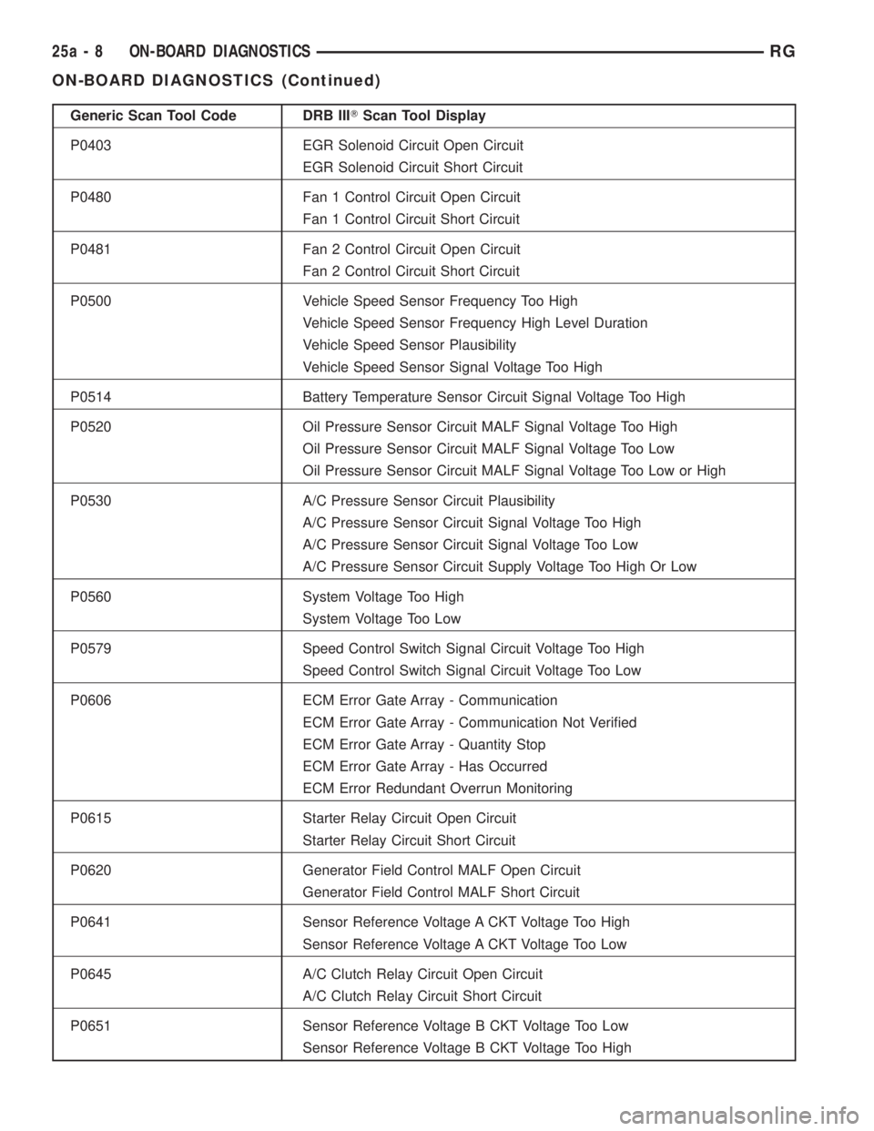
Generic Scan Tool Code DRB IIITScan Tool Display
P0403 EGR Solenoid Circuit Open Circuit
EGR Solenoid Circuit Short Circuit
P0480 Fan 1 Control Circuit Open Circuit
Fan 1 Control Circuit Short Circuit
P0481 Fan 2 Control Circuit Open Circuit
Fan 2 Control Circuit Short Circuit
P0500 Vehicle Speed Sensor Frequency Too High
Vehicle Speed Sensor Frequency High Level Duration
Vehicle Speed Sensor Plausibility
Vehicle Speed Sensor Signal Voltage Too High
P0514 Battery Temperature Sensor Circuit Signal Voltage Too High
P0520 Oil Pressure Sensor Circuit MALF Signal Voltage Too High
Oil Pressure Sensor Circuit MALF Signal Voltage Too Low
Oil Pressure Sensor Circuit MALF Signal Voltage Too Low or High
P0530 A/C Pressure Sensor Circuit Plausibility
A/C Pressure Sensor Circuit Signal Voltage Too High
A/C Pressure Sensor Circuit Signal Voltage Too Low
A/C Pressure Sensor Circuit Supply Voltage Too High Or Low
P0560 System Voltage Too High
System Voltage Too Low
P0579 Speed Control Switch Signal Circuit Voltage Too High
Speed Control Switch Signal Circuit Voltage Too Low
P0606 ECM Error Gate Array - Communication
ECM Error Gate Array - Communication Not Verified
ECM Error Gate Array - Quantity Stop
ECM Error Gate Array - Has Occurred
ECM Error Redundant Overrun Monitoring
P0615 Starter Relay Circuit Open Circuit
Starter Relay Circuit Short Circuit
P0620 Generator Field Control MALF Open Circuit
Generator Field Control MALF Short Circuit
P0641 Sensor Reference Voltage A CKT Voltage Too High
Sensor Reference Voltage A CKT Voltage Too Low
P0645 A/C Clutch Relay Circuit Open Circuit
A/C Clutch Relay Circuit Short Circuit
P0651 Sensor Reference Voltage B CKT Voltage Too Low
Sensor Reference Voltage B CKT Voltage Too High
25a - 8 ON-BOARD DIAGNOSTICSRG
ON-BOARD DIAGNOSTICS (Continued)
Page 3798 of 4284
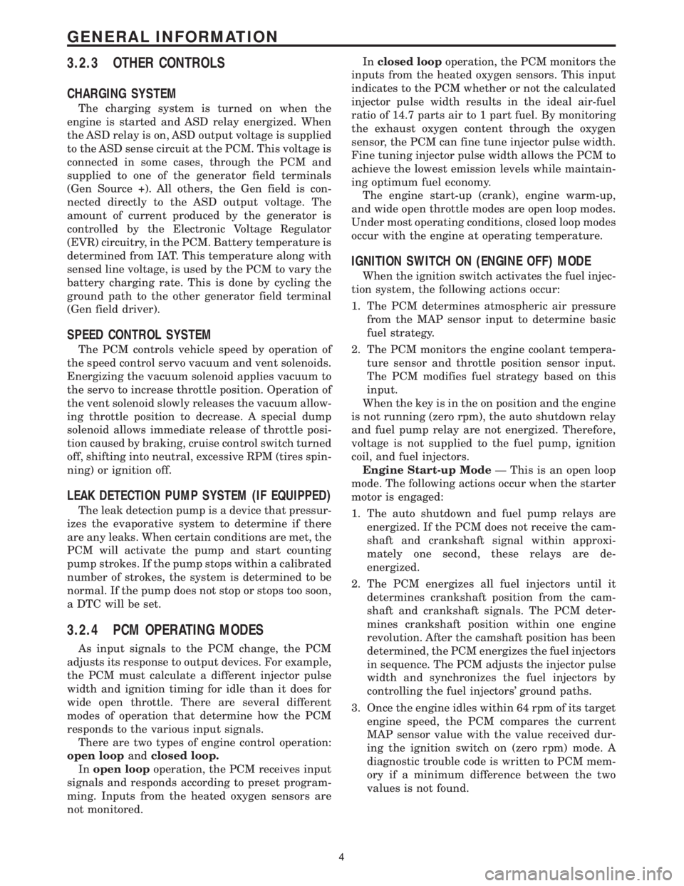
3.2.3 OTHER CONTROLS
CHARGING SYSTEM
The charging system is turned on when the
engine is started and ASD relay energized. When
the ASD relay is on, ASD output voltage is supplied
to the ASD sense circuit at the PCM. This voltage is
connected in some cases, through the PCM and
supplied to one of the generator field terminals
(Gen Source +). All others, the Gen field is con-
nected directly to the ASD output voltage. The
amount of current produced by the generator is
controlled by the Electronic Voltage Regulator
(EVR) circuitry, in the PCM. Battery temperature is
determined from IAT. This temperature along with
sensed line voltage, is used by the PCM to vary the
battery charging rate. This is done by cycling the
ground path to the other generator field terminal
(Gen field driver).
SPEED CONTROL SYSTEM
The PCM controls vehicle speed by operation of
the speed control servo vacuum and vent solenoids.
Energizing the vacuum solenoid applies vacuum to
the servo to increase throttle position. Operation of
the vent solenoid slowly releases the vacuum allow-
ing throttle position to decrease. A special dump
solenoid allows immediate release of throttle posi-
tion caused by braking, cruise control switch turned
off, shifting into neutral, excessive RPM (tires spin-
ning) or ignition off.
LEAK DETECTION PUMP SYSTEM (IF EQUIPPED)
The leak detection pump is a device that pressur-
izes the evaporative system to determine if there
are any leaks. When certain conditions are met, the
PCM will activate the pump and start counting
pump strokes. If the pump stops within a calibrated
number of strokes, the system is determined to be
normal. If the pump does not stop or stops too soon,
a DTC will be set.
3.2.4 PCM OPERATING MODES
As input signals to the PCM change, the PCM
adjusts its response to output devices. For example,
the PCM must calculate a different injector pulse
width and ignition timing for idle than it does for
wide open throttle. There are several different
modes of operation that determine how the PCM
responds to the various input signals.
There are two types of engine control operation:
open loopandclosed loop.
Inopen loopoperation, the PCM receives input
signals and responds according to preset program-
ming. Inputs from the heated oxygen sensors are
not monitored.Inclosed loopoperation, the PCM monitors the
inputs from the heated oxygen sensors. This input
indicates to the PCM whether or not the calculated
injector pulse width results in the ideal air-fuel
ratio of 14.7 parts air to 1 part fuel. By monitoring
the exhaust oxygen content through the oxygen
sensor, the PCM can fine tune injector pulse width.
Fine tuning injector pulse width allows the PCM to
achieve the lowest emission levels while maintain-
ing optimum fuel economy.
The engine start-up (crank), engine warm-up,
and wide open throttle modes are open loop modes.
Under most operating conditions, closed loop modes
occur with the engine at operating temperature.
IGNITION SWITCH ON (ENGINE OFF) MODE
When the ignition switch activates the fuel injec-
tion system, the following actions occur:
1. The PCM determines atmospheric air pressure
from the MAP sensor input to determine basic
fuel strategy.
2. The PCM monitors the engine coolant tempera-
ture sensor and throttle position sensor input.
The PCM modifies fuel strategy based on this
input.
When the key is in the on position and the engine
is not running (zero rpm), the auto shutdown relay
and fuel pump relay are not energized. Therefore,
voltage is not supplied to the fuel pump, ignition
coil, and fuel injectors.
Engine Start-up ModeÐ This is an open loop
mode. The following actions occur when the starter
motor is engaged:
1. The auto shutdown and fuel pump relays are
energized. If the PCM does not receive the cam-
shaft and crankshaft signal within approxi-
mately one second, these relays are de-
energized.
2. The PCM energizes all fuel injectors until it
determines crankshaft position from the cam-
shaft and crankshaft signals. The PCM deter-
mines crankshaft position within one engine
revolution. After the camshaft position has been
determined, the PCM energizes the fuel injectors
in sequence. The PCM adjusts the injector pulse
width and synchronizes the fuel injectors by
controlling the fuel injectors' ground paths.
3. Once the engine idles within 64 rpm of its target
engine speed, the PCM compares the current
MAP sensor value with the value received dur-
ing the ignition switch on (zero rpm) mode. A
diagnostic trouble code is written to PCM mem-
ory if a minimum difference between the two
values is not found.
4
GENERAL INFORMATION
Page 3800 of 4284
message the PCM will terminate engine operation,
or allow the engine to continue to operate.
3.2.7 SKIM ON-BOARD DIAGNOSTICS
The SKIM has been programmed to transmit and
monitor many different coded messages as well as
PCI Bus messages. This monitoring is called On
Board Diagnosis.
Certain criteria must be met for a diagnostic
trouble code to be entered into the SKIM memory.
The criteria may be a range of; Input voltage, PCI
Bus message, or coded messages to the SKIM. If all
of the criteria for monitoring a circuit or function
are met and a fault is sensed, a diagnostic trouble
code will be stored in the SKIM memory.
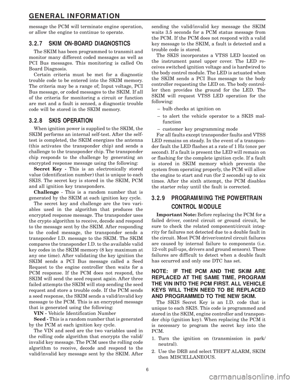
3.2.8 SKIS OPERATION
When ignition power is supplied to the SKIM, the
SKIM performs an internal self-test. After the self-
test is completed, the SKIM energizes the antenna
(this activates the transponder chip) and sends a
challenge to the transponder chip. The transponder
chip responds to the challenge by generating an
encrypted response message using the following:
Secret Key -This is an electronically stored
value (identification number) that is unique to each
SKIS. The secret key is stored in the SKIM, PCM
and all ignition key transponders.
Challenge- This is a random number that is
generated by the SKIM at each ignition key cycle.
The secret key and challenge are the two vari-
ables used in the algorithm that produces the
encrypted response message. The transponder uses
the crypto algorithm to receive, decode and respond
to the message sent by the SKIM. After responding
to the coded message, the transponder sends a
transponder I.D. message to the SKIM. The SKIM
compares the transponder I.D. to the available valid
key codes in the SKIM memory (8 key maximum at
any one time). After validating the key ignition the
SKIM sends a PCI Bus message called a Seed
Request to the engine controller then waits for a
PCM response. If the PCM does not respond, the
SKIM will send the seed request again. After three
failed attempts the SKIM will stop sending the seed
request and store a trouble code. If the PCM sends
a seed response, the SKIM sends a valid/invalid key
message to the PCM. This is an encrypted message
that is generated using the following:
VIN -Vehicle Identification Number
Seed -This is a random number that is generated
by the PCM at each ignition key cycle.
The VIN and seed are the two variables used in
the rolling code algorithm that encrypts the valid/
invalid key message. The PCM uses the rolling code
algorithm to receive, decode and respond to the
valid/invalid key message sent by the SKIM. Aftersending the valid/invalid key message the SKIM
waits 3.5 seconds for a PCM status message from
the PCM. If the PCM does not respond with a valid
key message to the SKIM, a fault is detected and a
trouble code is stored.
The SKIS incorporates a VTSS LED located on
the instrument panel upper cover. The LED re-
ceives switched ignition voltage and is hardwired to
the body control module. The LED is actuated when
the SKIM sends a PCI Bus message to the body
controller requesting the LED on. The body control-
ler then provides the ground for the LED. The
SKIM will request VTSS LED operation for the
following:
± bulb checks at ignition on
± to alert the vehicle operator to a SKIS mal-
function
± customer key programming mode
For all faults except transponder faults and VTSS
LED remains on steady. In the event of a transpon-
der fault the LED flashes at a rate of 1 Hz (once per
second). If a fault is present the LED will remain on
or flashing for the complete ignition cycle. If a fault
is stored in SKIM memory which prevents the
system from operating properly, the PCM will allow
the engine to start and run (for 2 seconds) up to six
times. After the sixth attempt, the PCM disables
the starter relay until the fault is corrected.
3.2.9 PROGRAMMING THE POWERTRAIN
CONTROL MODULE
Important Note:Before replacing the PCM for a
failed driver, control circuit or ground circuit, be
sure to check the related component/circuit integ-
rity for failures not detected due to a double fault in
the circuit. Most PCM driver/control circuit failures
are caused by internal failure to components (i.e.
12-volt pull-ups, drivers and ground sensors). These
failures are difficult to detect when a double fault
has occurred and only one DTC has set.
NOTE: IF THE PCM AND THE SKIM ARE
REPLACED AT THE SAME TIME, PROGRAM
THE VIN INTO THE PCM FIRST. ALL VEHICLE
KEYS WILL THEN NEED TO BE REPLACED
AND PROGRAMMED TO THE NEW SKIM.
The SKIS Secret Key is an I.D. code that is
unique to each SKIS. This code is programmed and
stored in the SKIM, engine controller and transpon-
der chip (ignition key). When replacing the PCM it
is necessary to program the secret key into the
PCM.
1. Turn the ignition on (transmission in park/
neutral).
2. Use the DRB and select THEFT ALARM, SKIM
then MISCELLANEOUS.
6
GENERAL INFORMATION
Page 3812 of 4284
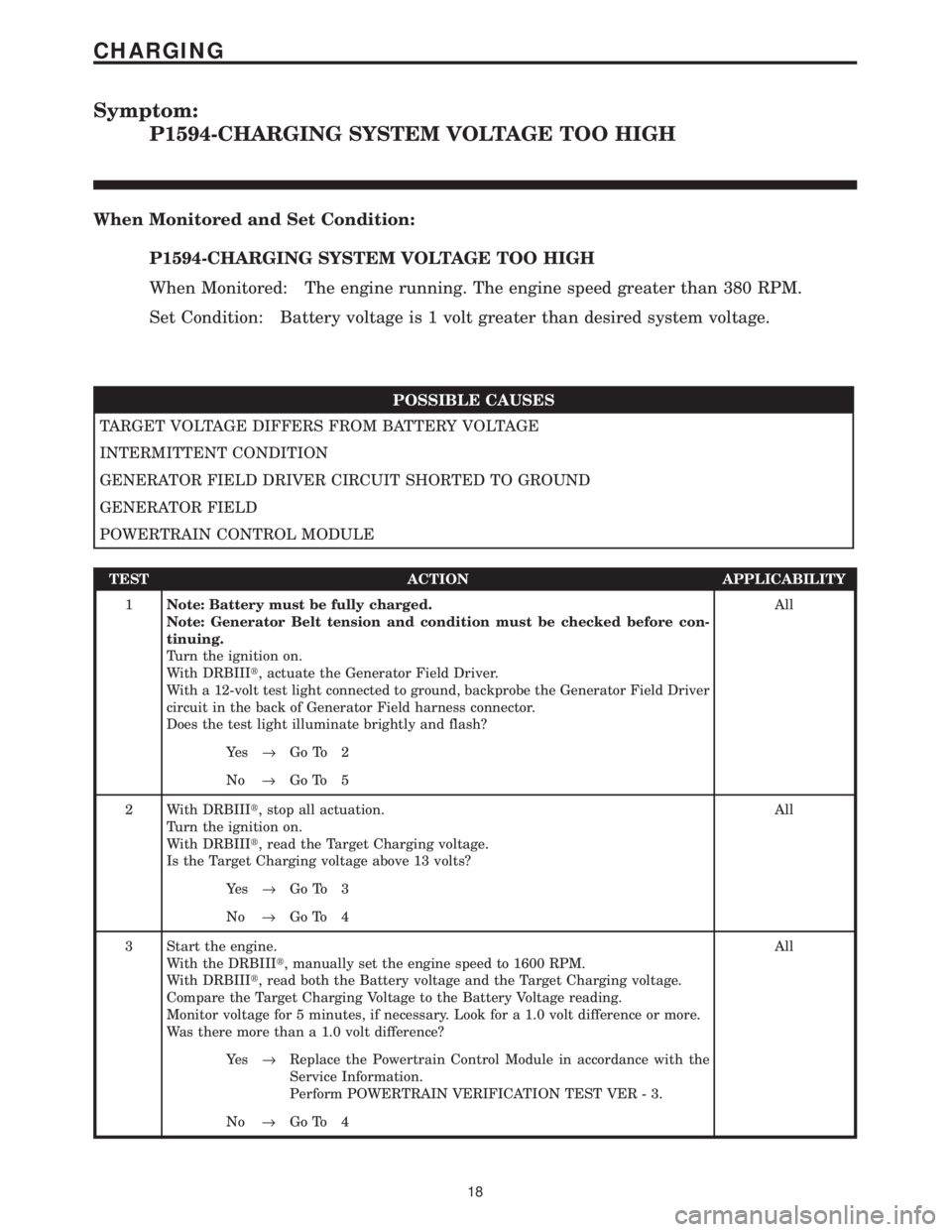
Symptom:
P1594-CHARGING SYSTEM VOLTAGE TOO HIGH
When Monitored and Set Condition:
P1594-CHARGING SYSTEM VOLTAGE TOO HIGH
When Monitored: The engine running. The engine speed greater than 380 RPM.
Set Condition: Battery voltage is 1 volt greater than desired system voltage.
POSSIBLE CAUSES
TARGET VOLTAGE DIFFERS FROM BATTERY VOLTAGE
INTERMITTENT CONDITION
GENERATOR FIELD DRIVER CIRCUIT SHORTED TO GROUND
GENERATOR FIELD
POWERTRAIN CONTROL MODULE
TEST ACTION APPLICABILITY
1Note: Battery must be fully charged.
Note: Generator Belt tension and condition must be checked before con-
tinuing.
Turn the ignition on.
With DRBIIIt, actuate the Generator Field Driver.
With a 12-volt test light connected to ground, backprobe the Generator Field Driver
circuit in the back of Generator Field harness connector.
Does the test light illuminate brightly and flash?All
Ye s®Go To 2
No®Go To 5
2 With DRBIIIt, stop all actuation.
Turn the ignition on.
With DRBIIIt, read the Target Charging voltage.
Is the Target Charging voltage above 13 volts?All
Ye s®Go To 3
No®Go To 4
3 Start the engine.
With the DRBIIIt, manually set the engine speed to 1600 RPM.
With DRBIIIt, read both the Battery voltage and the Target Charging voltage.
Compare the Target Charging Voltage to the Battery Voltage reading.
Monitor voltage for 5 minutes, if necessary. Look for a 1.0 volt difference or more.
Was there more than a 1.0 volt difference?All
Ye s®Replace the Powertrain Control Module in accordance with the
Service Information.
Perform POWERTRAIN VERIFICATION TEST VER - 3.
No®Go To 4
18
CHARGING
Page 3891 of 4284
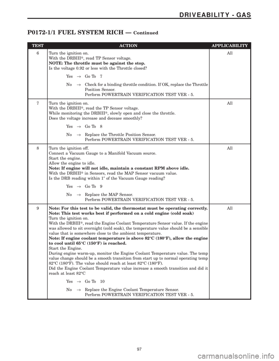
TEST ACTION APPLICABILITY
6 Turn the ignition on.
With the DRBIIIt, read TP Sensor voltage.
NOTE: The throttle must be against the stop.
Is the voltage 0.92 or less with the Throttle closed?All
Ye s®Go To 7
No®Check for a binding throttle condition. If OK, replace the Throttle
Position Sensor.
Perform POWERTRAIN VERIFICATION TEST VER - 5.
7 Turn the ignition on.
With the DRBIIIt, read the TP Sensor voltage.
While monitoring the DRBIIIt, slowly open and close the throttle.
Does the voltage increase and decease smoothly?All
Ye s®Go To 8
No®Replace the Throttle Position Sensor.
Perform POWERTRAIN VERIFICATION TEST VER - 5.
8 Turn the ignition off.
Connect a Vacuum Gauge to a Manifold Vacuum source.
Start the engine.
Allow the engine to idle.
Note: If engine will not idle, maintain a constant RPM above idle.
With the DRBIIItin Sensors, read the MAP Sensor vacuum value.
Is the DRB reading within 19of the Vacuum Gauge reading?All
Ye s®Go To 9
No®Replace the MAP Sensor.
Perform POWERTRAIN VERIFICATION TEST VER - 5.
9Note: For this test to be valid, the thermostat must be operating correctly.
Note: This test works best if performed on a cold engine (cold soak)
Turn the ignition on.
With the DRBIIIt, read the Engine Coolant Temperature Sensor value. If the engine
was allowed to sit overnight (cold soak), the temperature value should be a sensible
value that is somewhere close to the ambient temperature.
Note: If engine coolant temperature is above 82ÉC (180ÉF), allow the engine
to cool until 65ÉC (150ÉF) is reached.
Start the Engine.
During engine warm-up, monitor the Engine Coolant Temperature value. The temp
value change should be a smooth transition from start up to normal operating temp
82ÉC (180ÉF). The value should reach at least 82ÉC (180ÉF).
Did the Engine Coolant Temperature value increase a smooth transition and did it
reach at least 82ÉCAll
Ye s®Go To 10
No®Replace the Engine Coolant Temperature Sensor.
Perform POWERTRAIN VERIFICATION TEST VER - 5.
97
DRIVEABILITY - GAS
P0172-1/1 FUEL SYSTEM RICH ÐContinued
Page 3965 of 4284
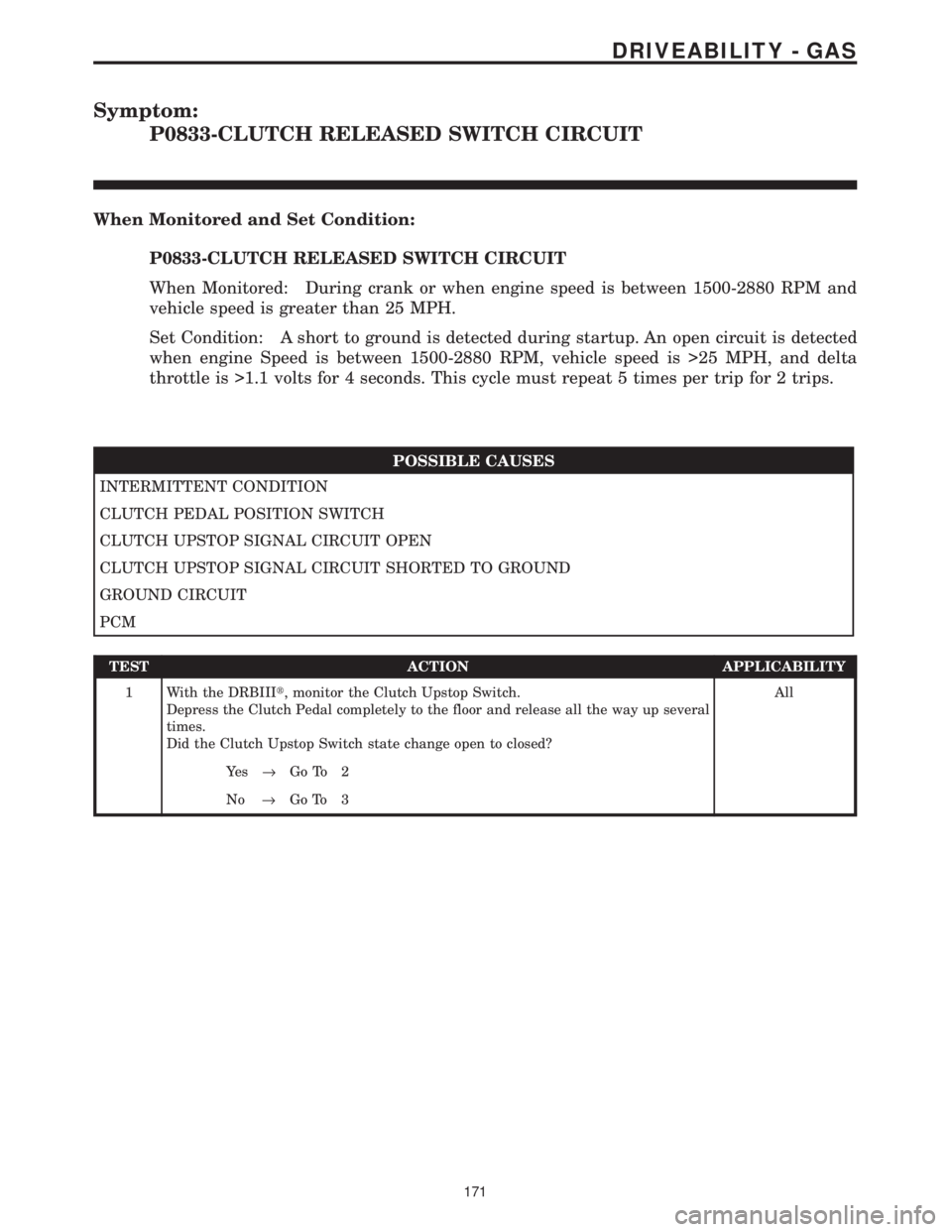
Symptom:
P0833-CLUTCH RELEASED SWITCH CIRCUIT
When Monitored and Set Condition:
P0833-CLUTCH RELEASED SWITCH CIRCUIT
When Monitored: During crank or when engine speed is between 1500-2880 RPM and
vehicle speed is greater than 25 MPH.
Set Condition: A short to ground is detected during startup. An open circuit is detected
when engine Speed is between 1500-2880 RPM, vehicle speed is >25 MPH, and delta
throttle is >1.1 volts for 4 seconds. This cycle must repeat 5 times per trip for 2 trips.
POSSIBLE CAUSES
INTERMITTENT CONDITION
CLUTCH PEDAL POSITION SWITCH
CLUTCH UPSTOP SIGNAL CIRCUIT OPEN
CLUTCH UPSTOP SIGNAL CIRCUIT SHORTED TO GROUND
GROUND CIRCUIT
PCM
TEST ACTION APPLICABILITY
1 With the DRBIIIt, monitor the Clutch Upstop Switch.
Depress the Clutch Pedal completely to the floor and release all the way up several
times.
Did the Clutch Upstop Switch state change open to closed?All
Ye s®Go To 2
No®Go To 3
171
DRIVEABILITY - GAS
Page 3979 of 4284
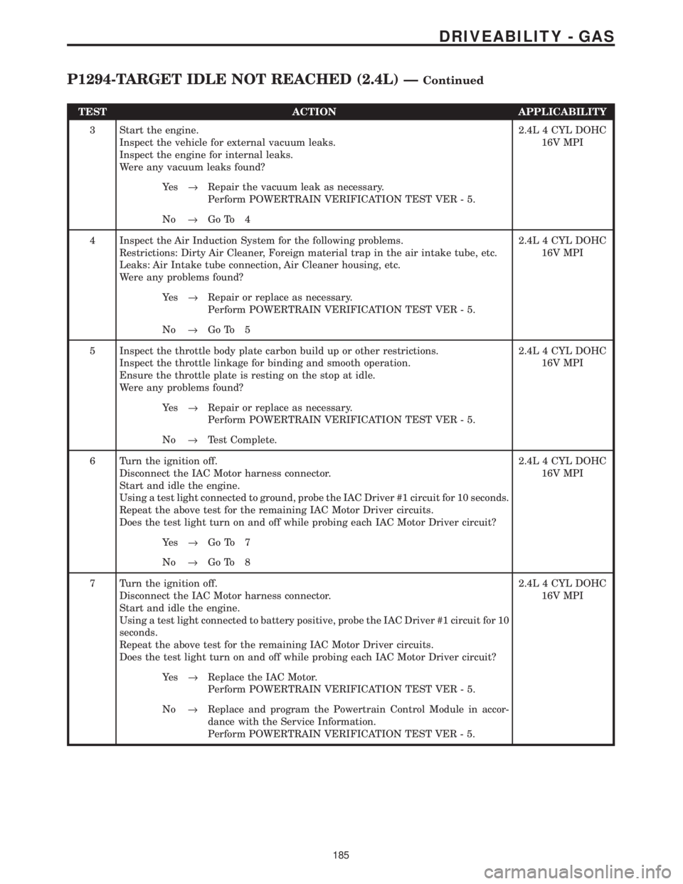
TEST ACTION APPLICABILITY
3 Start the engine.
Inspect the vehicle for external vacuum leaks.
Inspect the engine for internal leaks.
Were any vacuum leaks found?2.4L 4 CYL DOHC
16V MPI
Ye s®Repair the vacuum leak as necessary.
Perform POWERTRAIN VERIFICATION TEST VER - 5.
No®Go To 4
4 Inspect the Air Induction System for the following problems.
Restrictions: Dirty Air Cleaner, Foreign material trap in the air intake tube, etc.
Leaks: Air Intake tube connection, Air Cleaner housing, etc.
Were any problems found?2.4L 4 CYL DOHC
16V MPI
Ye s®Repair or replace as necessary.
Perform POWERTRAIN VERIFICATION TEST VER - 5.
No®Go To 5
5 Inspect the throttle body plate carbon build up or other restrictions.
Inspect the throttle linkage for binding and smooth operation.
Ensure the throttle plate is resting on the stop at idle.
Were any problems found?2.4L 4 CYL DOHC
16V MPI
Ye s®Repair or replace as necessary.
Perform POWERTRAIN VERIFICATION TEST VER - 5.
No®Test Complete.
6 Turn the ignition off.
Disconnect the IAC Motor harness connector.
Start and idle the engine.
Using a test light connected to ground, probe the IAC Driver #1 circuit for 10 seconds.
Repeat the above test for the remaining IAC Motor Driver circuits.
Does the test light turn on and off while probing each IAC Motor Driver circuit?2.4L 4 CYL DOHC
16V MPI
Ye s®Go To 7
No®Go To 8
7 Turn the ignition off.
Disconnect the IAC Motor harness connector.
Start and idle the engine.
Using a test light connected to battery positive, probe the IAC Driver #1 circuit for 10
seconds.
Repeat the above test for the remaining IAC Motor Driver circuits.
Does the test light turn on and off while probing each IAC Motor Driver circuit?2.4L 4 CYL DOHC
16V MPI
Ye s®Replace the IAC Motor.
Perform POWERTRAIN VERIFICATION TEST VER - 5.
No®Replace and program the Powertrain Control Module in accor-
dance with the Service Information.
Perform POWERTRAIN VERIFICATION TEST VER - 5.
185
DRIVEABILITY - GAS
P1294-TARGET IDLE NOT REACHED (2.4L) ÐContinued
Page 3980 of 4284
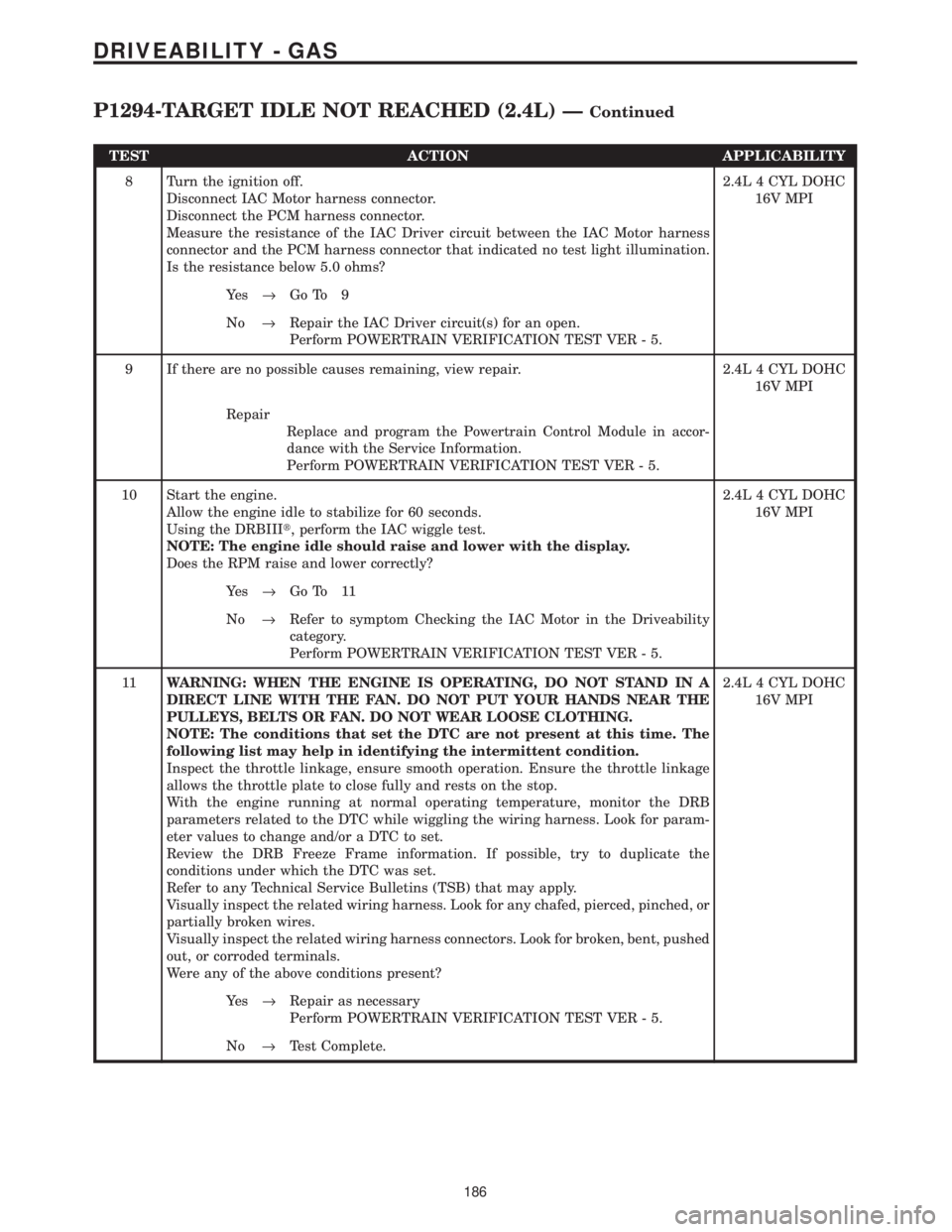
TEST ACTION APPLICABILITY
8 Turn the ignition off.
Disconnect IAC Motor harness connector.
Disconnect the PCM harness connector.
Measure the resistance of the IAC Driver circuit between the IAC Motor harness
connector and the PCM harness connector that indicated no test light illumination.
Is the resistance below 5.0 ohms?2.4L 4 CYL DOHC
16V MPI
Ye s®Go To 9
No®Repair the IAC Driver circuit(s) for an open.
Perform POWERTRAIN VERIFICATION TEST VER - 5.
9 If there are no possible causes remaining, view repair. 2.4L 4 CYL DOHC
16V MPI
Repair
Replace and program the Powertrain Control Module in accor-
dance with the Service Information.
Perform POWERTRAIN VERIFICATION TEST VER - 5.
10 Start the engine.
Allow the engine idle to stabilize for 60 seconds.
Using the DRBIIIt, perform the IAC wiggle test.
NOTE: The engine idle should raise and lower with the display.
Does the RPM raise and lower correctly?2.4L 4 CYL DOHC
16V MPI
Ye s®Go To 11
No®Refer to symptom Checking the IAC Motor in the Driveability
category.
Perform POWERTRAIN VERIFICATION TEST VER - 5.
11WARNING: WHEN THE ENGINE IS OPERATING, DO NOT STAND IN A
DIRECT LINE WITH THE FAN. DO NOT PUT YOUR HANDS NEAR THE
PULLEYS, BELTS OR FAN. DO NOT WEAR LOOSE CLOTHING.
NOTE: The conditions that set the DTC are not present at this time. The
following list may help in identifying the intermittent condition.
Inspect the throttle linkage, ensure smooth operation. Ensure the throttle linkage
allows the throttle plate to close fully and rests on the stop.
With the engine running at normal operating temperature, monitor the DRB
parameters related to the DTC while wiggling the wiring harness. Look for param-
eter values to change and/or a DTC to set.
Review the DRB Freeze Frame information. If possible, try to duplicate the
conditions under which the DTC was set.
Refer to any Technical Service Bulletins (TSB) that may apply.
Visually inspect the related wiring harness. Look for any chafed, pierced, pinched, or
partially broken wires.
Visually inspect the related wiring harness connectors. Look for broken, bent, pushed
out, or corroded terminals.
Were any of the above conditions present?2.4L 4 CYL DOHC
16V MPI
Ye s®Repair as necessary
Perform POWERTRAIN VERIFICATION TEST VER - 5.
No®Test Complete.
186
DRIVEABILITY - GAS
P1294-TARGET IDLE NOT REACHED (2.4L) ÐContinued
Page 3987 of 4284
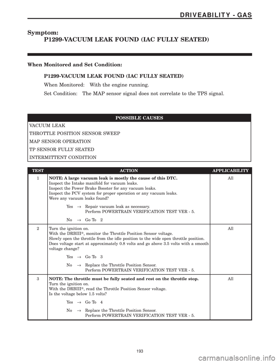
Symptom:
P1299-VACUUM LEAK FOUND (IAC FULLY SEATED)
When Monitored and Set Condition:
P1299-VACUUM LEAK FOUND (IAC FULLY SEATED)
When Monitored: With the engine running.
Set Condition: The MAP sensor signal does not correlate to the TPS signal.
POSSIBLE CAUSES
VACUUM LEAK
THROTTLE POSITION SENSOR SWEEP
MAP SENSOR OPERATION
TP SENSOR FULLY SEATED
INTERMITTENT CONDITION
TEST ACTION APPLICABILITY
1NOTE: A large vacuum leak is mostly the cause of this DTC.
Inspect the Intake manifold for vacuum leaks.
Inspect the Power Brake Booster for any vacuum leaks.
Inspect the PCV system for proper operation or any vacuum leaks.
Were any vacuum leaks found?All
Ye s®Repair vacuum leak as necessary.
Perform POWERTRAIN VERIFICATION TEST VER - 5.
No®Go To 2
2 Turn the ignition on.
With the DRBIIIt, monitor the Throttle Position Sensor voltage.
Slowly open the throttle from the idle position to the wide open throttle position.
Does voltage start at approximately 0.8 volts and go above 3.5 volts with a smooth
voltage change?All
Ye s®Go To 3
No®Replace the Throttle Position Sensor.
Perform POWERTRAIN VERIFICATION TEST VER - 5.
3NOTE: The throttle must be fully seated and rest on the throttle stop.
Turn the ignition on.
With the DRBIIIt, read the Throttle Position Sensor voltage.
Is the voltage below 1.5 volts?All
Ye s®Go To 4
No®Replace the Throttle Position Sensor.
Perform POWERTRAIN VERIFICATION TEST VER - 5.
193
DRIVEABILITY - GAS
Page 4048 of 4284
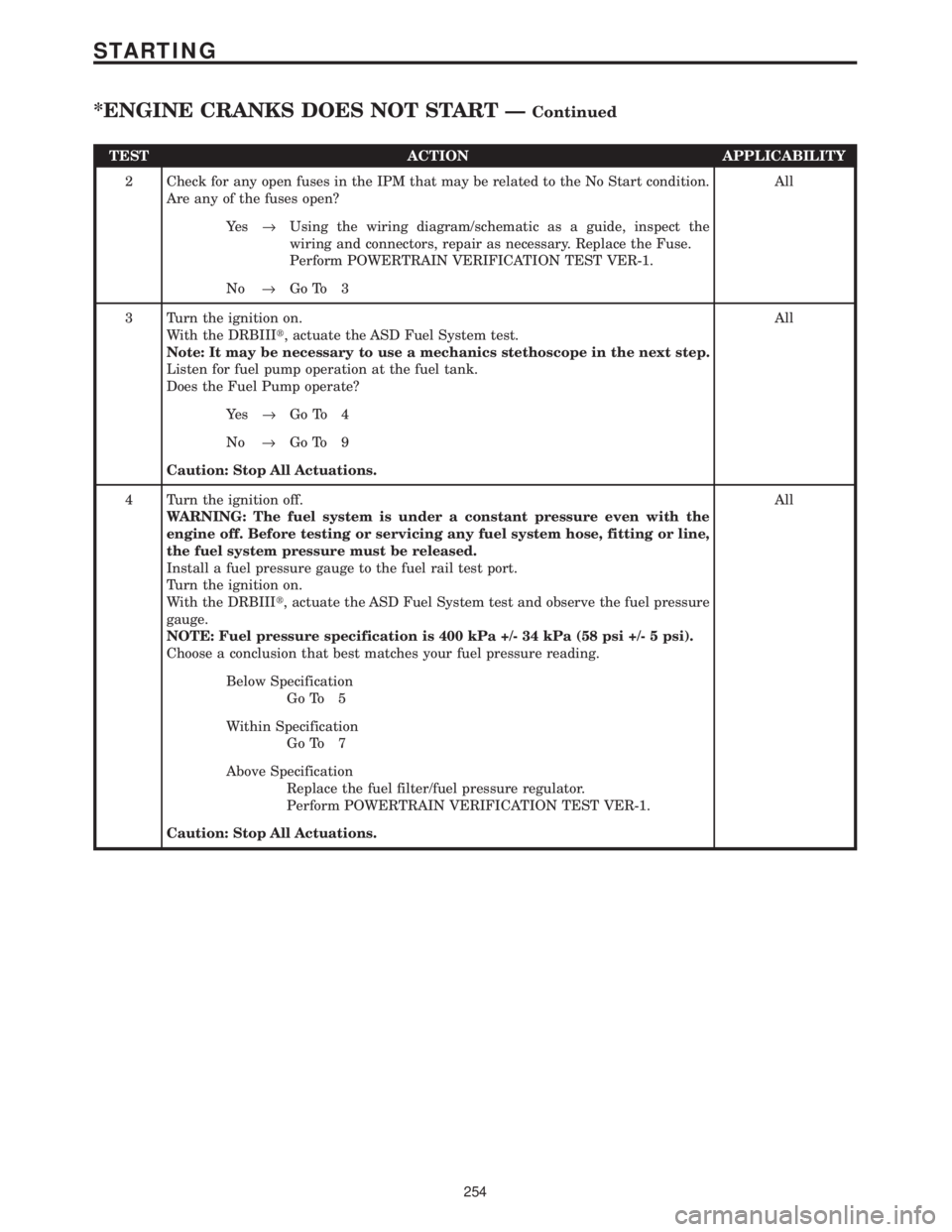
TEST ACTION APPLICABILITY
2 Check for any open fuses in the IPM that may be related to the No Start condition.
Are any of the fuses open?All
Ye s®Using the wiring diagram/schematic as a guide, inspect the
wiring and connectors, repair as necessary. Replace the Fuse.
Perform POWERTRAIN VERIFICATION TEST VER-1.
No®Go To 3
3 Turn the ignition on.
With the DRBIIIt, actuate the ASD Fuel System test.
Note: It may be necessary to use a mechanics stethoscope in the next step.
Listen for fuel pump operation at the fuel tank.
Does the Fuel Pump operate?All
Ye s®Go To 4
No®Go To 9
Caution: Stop All Actuations.
4 Turn the ignition off.
WARNING: The fuel system is under a constant pressure even with the
engine off. Before testing or servicing any fuel system hose, fitting or line,
the fuel system pressure must be released.
Install a fuel pressure gauge to the fuel rail test port.
Turn the ignition on.
With the DRBIIIt, actuate the ASD Fuel System test and observe the fuel pressure
gauge.
NOTE: Fuel pressure specification is 400 kPa +/- 34 kPa (58 psi +/- 5 psi).
Choose a conclusion that best matches your fuel pressure reading.All
Below Specification
Go To 5
Within Specification
Go To 7
Above Specification
Replace the fuel filter/fuel pressure regulator.
Perform POWERTRAIN VERIFICATION TEST VER-1.
Caution: Stop All Actuations.
254
STARTING
*ENGINE CRANKS DOES NOT START ÐContinued