Brake light CHRYSLER VOYAGER 2001 Service Manual
[x] Cancel search | Manufacturer: CHRYSLER, Model Year: 2001, Model line: VOYAGER, Model: CHRYSLER VOYAGER 2001Pages: 4284, PDF Size: 83.53 MB
Page 14 of 4284
TABLE OF CONTENTS - Continued
*BUS +/- SIGNALS OPEN OR NO RESPONSE FROM INSTRUMENT CLUSTER . .383
*BUS +/- SIGNALS OPEN OR NO RESPONSE FROM LEFT SLIDING DOOR
CONTROL MODULE....................................................386
*BUS +/- SIGNALS OPEN OR NO RESPONSE FROM POWER LIFTGATE
MODULE.............................................................389
*BUS +/- SIGNALS OPEN OR NO RESPONSE FROM RIGHT SLIDING DOOR
CONTROL MODULE....................................................392
*BUS +/- SIGNALS OPEN OR NO RESPONSE FROM THATCHAM ALARM
MODULE.............................................................395
*NO RESPONSE FROM CABIN HEATER ASSIST - DIESEL ONLY..............397
*NO RESPONSE FROM CONTROLLER ANTILOCK BRAKE...................399
*NO RESPONSE FROM ECM (PCI BUS) - DIESEL ONLY.....................401
*NO RESPONSE FROM ECM (SCI ONLY) - DIESEL ONLY....................402
*NO RESPONSE FROM FRONT CONTROL MODULE........................404
*NO RESPONSE FROM LEFT SIACM.....................................406
*NO RESPONSE FROM ORC............................................408
*NO RESPONSE FROM OVERHEAD CONSOLE............................410
*NO RESPONSE FROM PCM (PCI BUS)...................................412
*NO RESPONSE FROM PCM (SCI ONLY)..................................413
*NO RESPONSE FROM RADIO..........................................416
*NO RESPONSE FROM RIGHT SIACM....................................418
*NO RESPONSE FROM TRANSMISSION CONTROL MODULE................420
*PCI BUS COMMUNICATION FAILURE....................................423
DOOR AJAR
*HOOD AJAR CIRCUIT OPEN............................................426
*HOOD AJAR CIRCUIT SHORTED TO GROUND............................427
*LEFT FRONT DOOR AJAR SWITCH SENSE CIRCUIT OPEN.................428
*LEFT FRONT DOOR AJAR SWITCH SENSE CIRCUIT SHORTED TO GROUND. .429
*LEFT SLIDING DOOR AJAR SWITCH SENSE CIRCUIT OPEN................430
*LEFT SLIDING DOOR AJAR SWITCH SENSE CIRCUIT SHORTED TO
GROUND.............................................................432
*LIFTGATE AJAR CIRCUIT OPEN.........................................433
*LIFTGATE AJAR CIRCUIT SHORTED TO GROUND.........................434
*RIGHT FRONT DOOR AJAR SWITCH SENSE CIRCUIT OPEN................435
*RIGHT FRONT DOOR AJAR SWITCH SENSE CIRCUIT SHORTED TO
GROUND.............................................................436
*RIGHT SLIDING DOOR AJAR CIRCUIT OPEN.............................437
*RIGHT SLIDING DOOR AJAR CIRCUIT SHORTED TO GROUND..............439
ELECTRICALLY HEATED SYSTEMS
EBL RUN ONLY RELAY OPEN...........................................440
EBL RUN ONLY RELAY SHORTED TO BATTERY............................442
EXTERIOR LIGHTING
BACKUP LAMP OUTPUT OPEN..........................................443
BACKUP LAMP OUTPUT SHORT.........................................445
FRONT FOG LAMP RELAY OPEN........................................446
FRONT FOG LAMP SHORTED TO BATTERY...............................448
HEADLAMP SWITCH MISMATCH.........................................449
HEADLAMP SWITCH OPEN.............................................450
HEADLAMP SWITCH SHORT TO GROUND................................452
HIGH BEAM SWITCH INPUT OPEN.......................................454
xi
Page 37 of 4284
this type of system would only refer to this circuit.
A faulty speaker could not cause this DTC.
3.2.1 REMOTE RADIO CONTROLS
These radios can be controlled via remote radio
switches (optional). These switches are located on
the back side of the steering wheel. They control
mode, preset, seek up, seek down, volume up and
volume down functions.
These functions are inputs to the Body Control
Module and can be read with the DRBIIItunder
ªbody computerº. The switches are a multiplexed
signal to the BCM. The radio control MUX circuit is
a 5 volt line that is pulled to ground through
different value resistors built into the switches.
This causes a voltage drop to be seen by the BCM
and it sends a specific message to the radio on the
PCI Bus circuit. The radio then responses to the
message.
This circuit is fairly simple to troubleshoot. The
circuit must be complete from the switches in the
steering wheel to the BCM. The ground must be
complete so that the switches can cause the voltage
drop for the BCM to see. The circuit passes through
the clockspring so continuity through this devise
must be verified.
3.2.2 CD CHANGER
The new in-dash CD Changer is designed to fit
into the existing cubby bin in the center stack. This
new cartridge-less CD Changer is controlled by
your radio, and allows you to individually load up to
four discs at a time. However, due to its compact
design, the CD Changer can only carry out one
operation at a time. For example, you can not load
a new disc while playing another at the same time.
Each operation happens sequentially.
The radio unit installed with your system pro-
vides control over all features of the CD Changer
with the exception of the CD load and eject func-
tions, which are controlled by buttons located on the
front of the CD Changer. The radio also supplies the
power, ground, PCI Bus, left and right speaker
output thru a single DIN cable. All features you
would expect, such as Disc Up/Down, Track Up/
Down, Random and Scan are controlled by the
radio, which also displays all relevant CD Changer
information on the radio display.
The CD Changer contains a Load/Eject button
and an indicator light for each of the four disc
positions. The individual light indicates whether a
CD is currently loaded in that particular chamber of
the CD Changer. Pressing the individual Load/Eject
button for a particular chamber will eject a disc
currently present in that chamber. If the chamber iscurrently empty, actuating the Load/Eject button
will position that chamber to receive and load a new
disc in that chamber.
3.3 BODY CONTROL MODULE
The body control module (BCM) supplies vehicle
occupants with visual and audible information and
controls various vehicle functions. To provide and
receive information, the module is interfaced to the
vehicle's serial bus communications network (PCI).
This network consists of the powertrain control
module (PCM), the engine control module (ECM) -
diesel only, the transmission control module (TCM),
the mechanical instrument cluster (MIC), the front
control module (FCM), the occupant restraint con-
troller (ORC), the compass/mini-trip (CMTC), the
electronic vehicle information center (EVIC), the
controller antilock brake (CAB), the HVAC control
module (ATC & MTC), the power sliding door (Left
& Right) modules (PSD), the power liftgate module
(PLG), the Audio system, the side impact airbag
control (left & right) modules (SIACM), the memory
seat/mirror module (MSMM), the RKE/thatcham
alarm module and the sentry key immobilizer mod-
ule (SKIM). The BCM is operational when battery
power is supplied to the module.
The body control module provides the following
features:
²Power Door Locks
²Automatic Door Lock
²Door Lock Inhibit
²Central Locking (with VTSS Only)
²Battery Protection
²The BCM will automatically turn off all exterior
lamps after 3 minutes and all interior lamps after
15 minutes after the ignition is turned off, if they
are not turned off by the driver.
²Chime
²Compass/Minitrip Support
²Interior Lighting (Courtesy/Reading Lamps)
²BCM Diagnostic Reporting
²Electronic Liftgate Release (with Power Door
Locks)
²Exterior Lighting
²Power Folding Mirrors
²Remote Radio Controls
²Headlamp Time Delay (with/without Autohead-
lamps)
²Automatic Headlamps (with electrochromatic
mirror)
²Illuminated Entry
²Fade to Off
8
GENERAL INFORMATION
Page 40 of 4284
3.5 COMMUNICATION
The Programmable Communication Interface or
PCI Bus is a single wire multiplexed network capa-
ble of supporting binary encoded messages shared
between multiple modules. The PCI bus circuit is
identified as D25 and is white with a violet tracer.
Additional tracer colors may be added to the violet
in order to distinguish between different module
connections. The modules are wired in parallel.
Connections are made in the harness using splices.
One splice called the Diagnostic Junction Port,
serves as the ªHubº of the bus. The Diagnostic
Junction Port provides an access point to isolate
most of the modules on the bus in order to assist in
diagnosing the circuit. The following modules are
used on the RG:
²Body Control Module
²Front Control Module
²Occupant Restraint Controller
²Left Side Impact Airbag Control Module
²Right Side Impact Airbag Control Module
²Controller Antilock Brake
²Powertrain Control Module
²Engine Control Module - Diesel Only
²Radio
²CD Changer
²Transmission Control Module
²Automatic Temperature Control Module
²A/C Heater Control Module (MTC)
²Sentry Key Immobilizer Module
²RKE/Thatcham Alarm Module
²Memory Seat/Mirror Module
²Overhead Console
²Mechanical Instrument Cluster
²Left Sliding Door Control Module
²Right Sliding Door Control Module
²Power Liftgate Module
Each module provides its own bias and termina-
tion in order to transmit and receive messages. The
bus voltage is at zero volts when no modules are
transmitting and is pulled up to about seven and a
half volts when modules are transmitting.
The bus messages are transmitted at a rate
averaging 10800 bits per second. Since there is only
voltage present when the modules transmit and the
message length is only about 500 milliseconds, it is
ineffective to try and measure the bus activity witha conventional voltmeter. The preferred method is
to use the DRBIIItlab scope. The 12v square wave
selection on the 20-volt scale provides a good view of
the bus activity. Voltage on the bus should pulse
between zero and about seven and a half volts.
Refer to the following figure for some typical dis-
plays.
The PCI Bus failure modes are broken down into
two categories. Complete PCI Bus Communication
Failure and individual module no response. Causes
of complete PCI Bus Communication Failure in-
clude a short to ground or battery on the PCI
circuit. Individual module no response can be
caused by an open circuit at either the Diagnostic
Junction Port or the module, or an open battery or
ground circuit to the affected module.
Symptoms of a complete PCI Bus Communication
Failure would include but are not limited to:
²All gauges on the MIC stay at zero
²All telltales on MIC illuminate
²MIC backlighting at full intensity
²Dashed lines in the overhead console ambient
temperature display
²No response received from any module on the PCI
bus (except the PCM)
²No start (if equipped with Sentry Key Immobi-
lizer)
Symptoms of Individual module failure could
include any one or more of the above. The difference
would be that at least one or more modules would
respond to the DRBIIIt.
Diagnosis starts with symptom identification. If a
complete PCI Bus Communication Failure is sus-
pected, begin by identifying which modules the
vehicle is equipped with and then attempt to get a
response from the modules with the DRBIIIt.Ifany
modules are responding, the failure is not related to
the total bus, but can be caused by one or more
modules PCI circuit or power supply and ground
circuits. The DRBIIItmay display ªBUS +/- SIG-
NAL OPENº or ªNO RESPONSEº to indicate a
communication problem. These same messages will
be displayed if the vehicle is not equipped with that
particular module. The CCD error message is a
default message used by the DRBIIItand in no way
indicates whether or not the PCI bus is operational.
The message is only an indication that a module is
either not responding or the vehicle is not equipped.
11
GENERAL INFORMATION
Page 42 of 4284
3.7.6 EXTERIOR LIGHTING BATTERY
SAVER
The BCM monitors the status of, and controls, the
Park Lamps, Headlamps and Fog Lamp relays. If
any exterior lamps are left ON after the ignition is
turned OFF, the BCM will turn them OFF after 3
minutes.
3.7.7 AUTO HEADLAMPS
This feature is available on vehicles equipped
with both the Electrocromatic Mirror (ECM) and
the Compass/Mini-Trip Computer (CMTC). When
the BCM detects a day/night signal from the CMTC,
an ECM is present and Auto Headlamp mode is
selected.
3.8 FRONT CONTROL MODULE
The Front Control Module (FCM) is an electrical
control and interface center located in the engine
compartment. When it is mated to the Power Dis-
tribution Center (PDC), it is referred to as the
Intelligent Power Module (IPM). The IPM, with its
fuses and relays provides power and signal distri-
bution throughout most of the vehicle. The FCM
receives both hard wire and digital electronic inputs
from the vehicle electrical system through the PDC.
Based on these inputs and the ignition switch
position, it provides direct power feeds and relay
control to some of the vehicles' most critical electri-
cal systems.
The Front Control Module provides the following
features:
Controlled power feeds:
²Front airbag system
²Side airbag system
²Headlamp power
²EATX module power (4 speed only)
²Front washer motor
²Rear washer motor
²Brake shift interlock system
Relay controls:
²Fog lamp relay (when equipped)
²Park lamp relay
²Front wiper on relay
²Front wiper high/low relay
²Accessory relay
²Horn relay
²Front & rear blower relay
²Name brand speakers (NBS) relay
²Electronic back light (EBL) run only relay
²Cabin heater relayElectrical inputs:
²Headlamp battery supplies1&2
²Module battery supply
²Power ground
²Ignition switch RUN or START position status
²Ignition switch START only status
²PCI Bus
²Stop lamp switch
²Horn switch
²Back-up switch
²Wiper park switch
²Washer fluid level switch
²Brake fluid level switch
²Ambient temperature sensor
²Right park lamp outage
²Left park lamp outage
²Battery IOD
²Battery (+) connection detection
²Flash reprogramming voltage
3.8.1 CONTROLLED POWER FEEDS
Front airbag system
The FCM provides power to the Occupant Re-
straint Control (ORC) system through two ªfuse-
lessº circuits (ORC RUN/START, and ORC RUN
only). These circuits are electronically controlled
and continuously monitored for malfunctions.
Power is supplied while the ignition switch is in the
RUN and START positions on pin 48 of the FCM
connector, and in the RUN only position on pin 29.
Side airbag system
The FCM provides power to the Side Impact
Airbag Control Module (SIACM) system through
one ªfuselessº circuit. This circuit is electronically
controlled and continuously monitored for malfunc-
tions. Power is supplied in the ignition RUN and
START positions on pin 28 of the FCM connector.
Headlamp power
The headlamp switch is a direct input to the
BCM. The BCM sends a PCI Bus message to the
FCM informing it of a headlamp switch status
change. The FCM then turns on power to the
headlamps through four ªfuselessº circuits. These
circuits are electronically controlled and continu-
ously monitored for malfunctions. Power is supplied
to each filament in a separate circuit (RH low on pin
6, RH high on pin 4, LH low on pin 3 and LH high
on pin 5). For vehicles equipped with Daytime
Running Lamps (DRL), the FCM electronically
steps down the headlamp voltage to provide the
desired illumination.
13
GENERAL INFORMATION
Page 44 of 4284
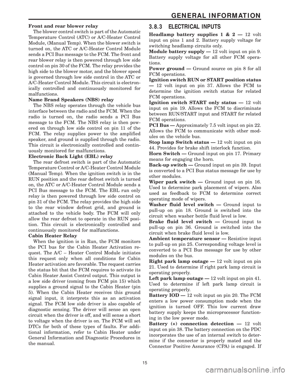
Front and rear blower relay
The blower control switch is part of the Automatic
Temperature Control (ATC) or A/C-Heater Control
Module, (Manual Temp). When the blower switch is
turned on, the ATC or A/C-Heater Control Module
sends a PCI Bus message to the FCM. The front and
rear blower relay is then powered through low side
control on pin 30 of the FCM. The relay provides the
high side to the blower motor, and the blower speed
is governed through low side control in the ATC or
A/C-Heater Control Module. This circuit is electron-
ically controlled and continuously monitored for
malfunctions.
Name Brand Speakers (NBS) relay
The NBS relay operates through the vehicle bus
interface between the radio and the FCM. When the
radio is turned on, the radio sends a PCI Bus
message to the FCM. The NBS relay is then pow-
ered on through low side control on pin 11 of the
FCM. The relay supplies power to the amplified
speaker, and ground is supplied through the radio.
This circuit is electronically controlled and contin-
uously monitored for malfunctions.
Electronic Back Light (EBL) relay
The rear defrost switch is part of the Automatic
Temperature Control or A/C-Heater Control Module
(Manual Temp). When the ignition switch is in the
RUN position and the rear defrost switch is turned
on, the ATC or A/C-Heater Control Module sends a
PCI Bus message to the FCM. The EBL run only
relay is then powered through low side control on
pin 31 of the FCM. The relay provides the high side
to the rear window defrost grid, and ground is
attached to the vehicle body. The FCM will only
allow the rear defrost to operate in the RUN posi-
tion. This circuit is electronically controlled and
continuously monitored for malfunctions.
Cabin Heater Relay
When the ignition is in Run, the FCM monitors
the PCI bus for the Cabin Heater Activation re-
quest. The A/C ± Heater Control Module initiates
this request only when all conditions for Cabin
Heater activation are favorable. The request carries
the status bit that the FCM requires to activate its
Cabin Heater Assist Control output. This output is
a low side driver (coming from FCM pin 15) which
supplies a ground signal to the Cabin Heater (pin
5). When the Cabin Heater receives this ground
signal input, it interprets this as an activation
signal. The FCM low side driver is also capable of
diagnostic sensing. The driver will sense an open
circuit when the driver is off, and will sense a short
to voltage when the driver is on. The FCM will set
DTCs for both of these types of faults. For addi-
tional information, refer to Cabin Heater under
General Information and Diagnostic Procedures in
the manual.3.8.3 ELECTRICAL INPUTS
Headlamp battery supplies1&2Ð12 volt
input on pins 1 and 2. Battery supply voltage for
switching headlamp circuits only.
Module battery supply Ð12 volt input on pin 9.
Battery supply voltage for all other FCM opera-
tions.
Power ground ÐGround source on pin 8 for all
FCM operations.
Ignition switch RUN or START position status
Ð12 volt input on pin 37. Allows the FCM to
determine the ignition switch status for related
FCM operations.
Ignition switch START only status Ð12 volt
input on pin 19. Allows the FCM to discriminate
between RUN/START input and START for related
FCM operations.
PCI Bus ÐApproximately 7.5 volt input on pin 22.
Allows the FCM to communicate with other mod-
ules on the vehicle bus.
Stop lamp Switch status Ð12 volt input on pin
44. Provides for brake shift interlock function.
Horn Switch ÐGround input on pin 17. Primary
means for engaging the horn.
Back-up switch ÐGround input on pin 39. Input
is converted to a PCI Bus status message for use by
other modules.
Wiper park switch ÐGround input on pin 16.
Used to determine park placement of wipers. Also
used as feedback to FCM to determine correct
operating mode of wipers.
Washer fluid level switch ÐGround input to
pull-up on pin 18. Ground is switched into the
circuit when washer bottle fluid level is low.
Brake fluid level switch ÐGround input to
pull-up on pin 36. Ground is switched into the
circuit when brake fluid level is low.
Ambient temperature sensor ÐResistive input
to pull-up on pin 25. Corresponding voltage level is
converted to a PCI Bus message for use by other
modules on the bus.
Right park lamp outage Ð12 volt input on pin
21. Used to determine if right park lamp circuit is
operating properly.
Left park lamp outage Ð12 volt input on pin 41.
Used to determine if left park lamp circuit is
operating properly.
Battery IOD Ð12 volt input on pin 20. The FCM
enters a low power consumption mode when the
ignition is turned OFF. This low current draw
battery supply keeps the microprocessor function-
ing in the low power mode.
Battery (+) connection detection Ð12 volt
input on pin 38. The battery connection on the PDC
incorporates the use of an internal switch to deter-
mine if the connector is properly mated and the
Connector Positive Assurance (CPA) is engaged. If
15
GENERAL INFORMATION
Page 57 of 4284
defined as the amount of time from the start of a
wipe to the beginning of the next wipe. The rear
wiper system delay time is based on the following:
7.75 - (MPH x .05) = Seconds delay
Examples:
At zero (0) MPH the delay is 7.75 seconds.
At 100 MPH the delay is 2.75 seconds.
3.21.8 WIPE AFTER WASH
When the driver presses the wash button for over
1.5 seconds and releases it, the wiper will continue
to run for 2 additional wipe cycles.
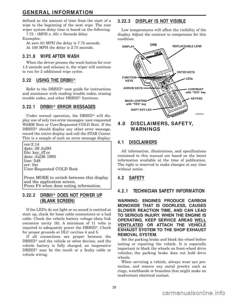
3.22 USING THE DRBIIIT
Refer to the DRBIIItuser guide for instructions
and assistance with reading trouble codes, erasing
trouble codes, and other DRBIIItfunctions.
3.22.1 DRBIIITERROR MESSAGES
Under normal operation, the DRBIIItwill dis-
play one of only two error messages: user-requested
WARM Boot or User-Requested COLD Boot. If the
DRBIIItshould display any other error message,
record the entire display and call the STAR Center.
This is a sample of such an error message display:
ver:2.14
date: 26 Jul93
file: key_iff.cc
date: Jul26 1993
line: 548
err: 0xi
User-Requested COLD Boot
Press MORE to switch between this display
and the application screen.
Press F4 when done noting information.
3.22.2 DRBIIITDOES NOT POWER UP
(BLANK SCREEN)
If the LED's do not light or no sound is emitted at
start up, check for loose cable connections or a bad
cable. Check the vehicle battery voltage (data link
connector cavity 16). A minimum of 11 volts is
required to adequately power the DRBIIIt. Check
for proper grounds at DLC cavities 4 and 5.
If all connections are proper between the
DRBIIItand the vehicle or other devices, and the
vehicle battery is fully charged, an inoperative
DRBIIItmay be the result or a faulty cable or
vehicle wiring.
3.22.3 DISPLAY IS NOT VISIBLE
Low temperatures will affect the visibility of the
display. Adjust the contrast to compensate for this
condition.
4.0 DISCLAIMERS, SAFETY,
WARNINGS
4.1 DISCLAIMERS
All information, illustrations, and specifications
contained in this manual are based on the latest
information available at the time of publication.
The right is reserved to make changes at any time
without notice.
4.2 SAFETY
4.2.1 TECHNICIAN SAFETY INFORMATION
WARNING: ENGINES PRODUCE CARBON
MONOXIDE THAT IS ODORLESS, CAUSES
SLOWER REACTION TIME, AND CAN LEAD
TO SERIOUS INJURY. WHEN THE ENGINE IS
OPERATING, KEEP SERVICE AREAS WELL
VENTILATED OR ATTACH THE VEHICLE
EXHAUST SYSTEM TO THE SHOP EXHAUST
REMOVAL SYSTEM.
Set the parking brake and block the wheel before
testing or repairing the vehicle. It is especially
important to block the wheels on front-wheel drive
vehicles; the parking brake does not hold drive
wheels.
When servicing a vehicle, always wear eye pro-
tection, and remove any metal jewelry such as
rings, watchbands or bracelets that might make an
inadvertent electrical contact.
28
GENERAL INFORMATION
Page 59 of 4284
WARNING: BEFORE ROAD TESTING A
VEHICLE, BE SURE THAT ALL
COMPONENTS ARE REASSEMBLED.
DURING THE TEST DRIVE, DO NOT TRY TO
READ THE DRBIIITSCREEN WHILE IN
MOTION. DO NOT HANG THE DRBIIITFROM
THE REAR VIEW MIRROR OR OPERATE IT
YOURSELF. HAVE AN ASSISTANT
AVAILABLE TO OPERATE THE DRBIIIT.
5.0 REQUIRED TOOLS AND
EQUIPMENT
DRBIIIt(diagnostic read-out box)
Jumper wires
Ohmmeter
Voltmeter
Sentry Key Tester
Test Light
8310 Airbag System Load Tool
8443 SRS Airbag System Load Tool
Diagnostic Junction Port Tester 8339
6.0 GLOSSARY OF TERMS
ABSantilock brake system
ACMairbag control module
AECMairbag electronic control module
(ACM)
ASDMairbag system diagnostic module
(ACM)
AT Cautomatic temperature control
BCMbody control module
CABcontroller antilock brake
CMTCcompass/mini-trip computer
CPAconnector positive assurance
DABdriver airbag
DCHAdiesel cabin heater assist
(cabin heater)
DLCdata link connector
DTCdiagnostic trouble code
DRdriver
EBLelectric back lite (rear window de-
fogger)ECMEngine control module
EVICelectronic vehicle information center
FCMfront control module
GCCGulf Coast Countries
HVACheater ventilation, air conditioning
IPMintelligent power module
LDUlower drive unit
LHDLeft Hand Drive
MICmechanical instrument cluster
MTCmanual temperature control
MSMMmemory seat/mirror module
OBDon board diagnostics
ODOodometer
ORCoccupant restraint controller
PA Bpassenger airbag
PASSpassenger
PCIProgrammable Communication In-
terface (vehicle communication bus)
PCMpowertrain control module
PDCpower distribution center
PLGpower liftgate
PLGMpower liftgate module
PSDpower sliding door
PSDMpower sliding door module
PWMpulse width modulated
RHDRight Hand Drive
RKEremote keyless entry
SABseat airbag
SBTseat belt tensioner
SIACMside impact airbag control module
SKIMsentry key immobilizer module
SKISsentry key immobilizer system
SQUIBalso called initiator (located inside
airbag)
SRSsupplemental restraint system
TCMtransmission control module
VFDvacuum fluorescent display
VTSSvehicle theft security system
30
GENERAL INFORMATION
Page 408 of 4284

Symptom:
*BUS +/- SIGNALS OPEN OR NO RESPONSE FROM BODY CON-
TROL MODULE
POSSIBLE CAUSES
ATTEMPT TO COMMUNICATE WITH ANOTHER MODULE
FUSED (B+) CKT OPEN
OPEN GROUND CIRCUIT(S)
OPEN PCI BUS CIRCUIT
BODY CONTROL MODULE
TEST ACTION APPLICABILITY
1 Turn the ignition on.
With the DRB, attempt to communicate with the Airbag Control Module (ACM).
With the DRB, attempt to communicate with the Controller Antilock Brake (CAB)
module.
Was the DRB able to I/D or communicate with the ACM and the CAB?All
Ye s®Go To 2
No®Refer to symptom list for problems related to the PCI Bus
Communication Failure.
Perform BODY VERIFICATION TEST - VER 1.
2 Turn the ignition off.
Disconnect the BCM C2 harness connector.
Using a 12-volt test light connected to ground, probe the Fused B+ circuit.
Is the test light illuminated?All
Ye s®Go To 3
No®Check fuse #14 in the IPM for an open. If ok, repair the Fused B+
circuit for an open or short. Refer to the wiring diagrams in the
service information.
Perform BODY VERIFICATION TEST - VER 1.
3 Turn the ignition off.
Disconnect the BCM C2 harness connector.
Measure the resistance between ground and both Ground circuits.
Is the resistance below 10.0 ohms for each measurement?All
Ye s®Go To 4
No®Repair the Ground circuit(s) for an open.
Perform BODY VERIFICATION TEST - VER 1.
379
COMMUNICATION
Page 428 of 4284

Symptom:
*NO RESPONSE FROM CONTROLLER ANTILOCK BRAKE
POSSIBLE CAUSES
NO RESPONSE FROM CAB
GROUND CIRCUIT OPEN
OPEN FUSED IGNITION SWITCH OUTPUT CIRCUIT
OPEN PCI BUS CIRCUIT
CONTROLLER ANTILOCK BRAKE
TEST ACTION APPLICABILITY
1 Turn the ignition on.
Note: As soon as one or more module communicates with the DRB, answer
the question.
With the DRB, attempt to communicate with the Airbag Control Module (ACM).
With the DRB, attempt to communicate with the Body Control Module (BCM).
Was the DRB able to I/D or establish communications with either of the modules?All
Ye s®Go To 2
No®Refer to the Communications category and perform the symptom
PCI Bus Communication Failure.
Perform ABS VERIFICATION TEST - VER 1.
2 Turn the ignition off.
Disconnect the CAB harness connector.
Measure the resistance between ground and both ground circuits.
Is the resistance below 5.0 ohms for both measurements?All
Ye s®Go To 3
No®Repair the ground circuit(s) for an open.
Perform ABS VERIFICATION TEST - VER 1.
3 Turn the ignition off.
Disconnect the CAB harness connector.
Turn the ignition on.
Using a 12-volt test light connected to ground, probe the Fused Ignition Switch
Output circuit.
Is the test light illuminated?All
Ye s®Go To 4
No®Repair the Fused Ignition Switch Output circuit for an open.
Perform ABS VERIFICATION TEST - VER 1.
399
COMMUNICATION
Page 1161 of 4284
the brake pedal is applied the test will be run at 40
km/h (24 mph) regardless of brake switch state. If,
during the dynamic test, the brake pedal is applied,
the driver may feel the test through brake pedal
pulsations. This is a normal condition.
If any component exhibits a trouble condition
during system initialization or dynamic check, the
CAB will illuminate the ABS warning indicator and
TRAC OFF lamp if equipped.
3.3.6 DIAGNOSTIC MODE
To enter diagnostic mode, a vehicle speed must be
below 10 km/h (6 mph) and no ABS condition
present. If vehicle speed is not below 10 km/h
(6 mph), a ªNo Responseº message could be dis-
played by the DRBIIIt. The following are charac-
teristics of diagnostic mode:
± The amber ABS warning indicator will blink
rapidly (about 1/2 second ON and 1/2 second
OFF). If a hard trouble code, such as Valve
Power Feed Failure code is present, the indi-
cator will be illuminated without blinking un-
til the trouble condition is cleared.
± Antilock operation is disabled.
± The HCU valves cannot be actuated when the
vehicle speed is above 8 km/h (5 mph). If valve
actuation is attempted above 8 km/h (5 mph), a
ªNo Responseº message will be displayed on
the DRBIIIt.
3.4 DIAGNOSTIC TROUBLE CODES
The controller antilock brake may report any of
the following diagnostic trouble codes:
CLUSTER LAMP FAILURE
VALVE POWER FEED FAILURE
BUS SYSTEM COMMUNICATION FAILURE
CAB INTERNAL FAILURE
LEFT FRONT SENSOR CIRCUIT FAILURE
LEFT FRONT WHEEL SPEED SIGNAL
FAILURE
LEFT REAR SENSOR CIRCUIT FAILURE
LEFT REAR WHEEL SPEED SIGNAL
FAILURE
PUMP CIRCUIT FAILURE
RIGHT FRONT SENSOR CIRCUIT FAILURE
RIGHT FRONT WHEEL SPEED SIGNAL
FAILURE
RIGHT REAR SENSOR CIRCUIT FAILURE
RIGHT REAR WHEEL SPEED SIGNAL
FAILURE
SYSTEM OVERVOLTAGE
SYSTEM UNDERVOLTAGE
3.5 DRBIIITERROR MESSAGES AND
BLANK SCREEN
Under normal operation, the DRBIIItwill dis-
play one of only two error messages:
± User-Requested WARM Boot or User-
Requested COLD Boot.
If the DRBIIItshould display any other error
message, record the entire display and call the
STAR Center for information. This is a sample of
such an error message display:
ver: 2.14
date: 26 Jul93
file: key_itf.cc
date: Jul 26 1993
line: 548
err. 0x1
User-Requested COLD boot Press MORE to
switch between this display
and the application screen.
Press F4 when done noting information.
3.5.1 DRBIIITDOES NOT POWER UP
If the LED's do not light or no sound is emitted at
start up, check for loose cable connections or a bad
cable. Check the vehicle battery voltage (data link
connector cavity 16). A minimum of 11 volts is
required to adequately power the DRBIIIt.
If all connections are proper between the
DRBIIItand the vehicle or other devices, and the
vehicle battery is fully charged, an inoperative
DRBIIItmay be the result of faulty cable or vehicle
wiring.
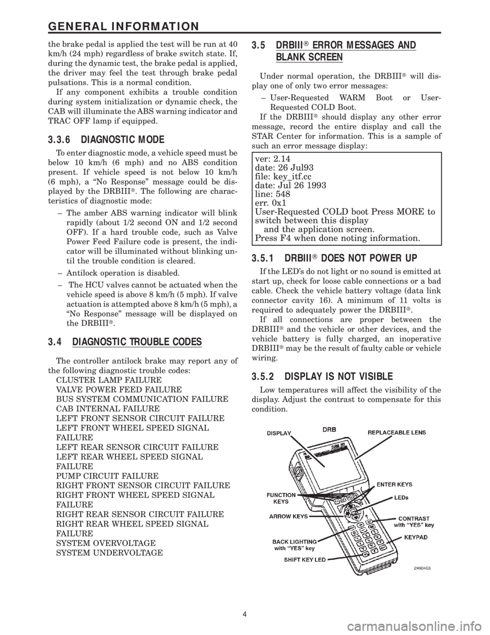
3.5.2 DISPLAY IS NOT VISIBLE
Low temperatures will affect the visibility of the
display. Adjust the contrast to compensate for this
condition.
4
GENERAL INFORMATION