air condition CHRYSLER VOYAGER 2001 Service Manual
[x] Cancel search | Manufacturer: CHRYSLER, Model Year: 2001, Model line: VOYAGER, Model: CHRYSLER VOYAGER 2001Pages: 4284, PDF Size: 83.53 MB
Page 4 of 4284
TABLE OF CONTENTS
1.0 INTRODUCTION.........................................................1
1.1SYSTEM COVERAGE...............................................1
1.2SIX-STEP TROUBLESHOOTING PROCEDURE..........................1
2.0 IDENTIFICATION OF SYSTEM.............................................1
3.0 SYSTEM DESCRIPTION AND FUNCTIONAL OPERATION......................1
3.1AIRBAG SYSTEM/OCCUPANT RESTRAINT CONTROLLER SYSTEM........2
3.1.1DRIVER AIRBAG...........................................3
3.1.2CLOCKSPRING............................................4
3.1.3PASSENGER AIRBAG......................................4
3.1.4SEAT BELT TENSIONER (SBT)...............................5
3.1.5SEAT BELT SWITCHES (SBS)................................5
3.1.6SIDE IMPACT AIRBAG CONTROL MODULE (SIACM)............5
3.1.7SEAT AIRBAGS (SAB)......................................6
3.1.8ORC/SIACM DIAGNOSTIC TROUBLE CODES..................6
3.1.9ACTIVE CODES...........................................7
3.1.10STORED CODES..........................................7
3.2AUDIO SYSTEM....................................................7
3.2.1REMOTE RADIO CONTROLS................................8
3.2.2CD CHANGER.............................................8
3.3BODY CONTROL MODULE...........................................8
3.4CHIME WARNING SYSTEM...........................................9
3.4.1CHIME PRIORITY..........................................9
3.4.2CHIME ON CONDITIONS....................................9
3.4.3WARNING LAMP ANNOUNCEMENT.........................10
3.4.4OTHER CHIME ON CONDITIONS............................10
3.5COMMUNICATION.................................................11
3.6DOOR AJAR SYSTEM..............................................12
3.7EXTERIOR LIGHTING SYSTEM......................................12
3.7.1HEADLAMP POWER......................................12
3.7.2HEADLAMP SWITCH......................................12
3.7.3PARK LAMP RELAY.......................................12
3.7.4FOG LAMP RELAY........................................12
3.7.5FOG LAMPS.............................................12
3.7.6EXTERIOR LIGHTING BATTERY SAVER......................13
3.7.7AUTO HEADLAMPS.......................................13
3.8FRONT CONTROL MODULE.........................................13
3.8.1CONTROLLED POWER FEEDS.............................13
3.8.2RELAY CONTROLS.......................................14
3.8.3ELECTRICAL INPUTS.....................................15
3.9HEATING & A/C...................................................16
3.9.1AUTOMATIC TEMPERATURE CONTROL (ATC)................16
3.9.1.1CABIN HEATER..........................................16
3.9.1.2SYSTEM OPERATION.....................................16
3.9.1.3BLOWER MOTOR OPERATION.............................16
3.9.1.4INFRARED SENSORS.....................................16
3.9.1.5REAR ATC SWITCH.......................................16
3.9.1.6COOLDOWN TESTING....................................16
3.9.1.7ACTIVE AND STORED TROUBLE CODES....................17
3.9.2MANUAL TEMPERATURE CONTROL.........................17
i
Page 12 of 4284
TABLE OF CONTENTS - Continued
FRONT IR SENSOR CHANGE TOO LARGE (ACTIVE)........................245
FRONT IR SENSOR HIGH (ACTIVE)......................................245
FRONT IR SENSOR LOW (ACTIVE).......................................245
FRONT IR SENSOR NOT CALIBRATED (ACTIVE)...........................246
FRONT KEYBOARD FAULT (ACTIVE).....................................246
FRONT KEYBOARD COMMUNICATION FAULT (ACTIVE).....................251
FRONT MODE DOOR NOT RESPONDING (ACTIVE).........................252
FRONT MODE DOOR TRAVEL TOO LARGE (ACTIVE).......................254
FRONT MODE DOOR TRAVEL TOO SMALL (ACTIVE).......................256
INVALID CONDITIONS FOR COOLDOWN TEST, EVAP TEMPERATURE TOO
LOW.................................................................258
PASS BLEND DOOR NOT RESPONDING (ACTIVE)..........................261
PASS BLEND DOOR TRAVEL TOO LARGE (ACTIVE)........................263
PASS BLEND DOOR TRAVEL TOO SMALL (ACTIVE)........................265
PCI BUS SHORTED HIGH (ACTIVE)......................................267
PCI BUS SHORTED LOW (ACTIVE).......................................267
REAR BLEND DOOR NOT RESPONDING (ACTIVE).........................268
REAR BLEND DOOR TRAVEL TOO LARGE (ACTIVE)........................270
REAR BLEND DOOR TRAVEL TOO SMALL (ACTIVE)........................272
REAR FAN POT OPEN (ACTIVE).........................................274
REAR FAN POT SHORTED (ACTIVE).....................................274
REAR IR SENSOR HIGH (ACTIVE).......................................274
REAR IR SENSOR LOW (ACTIVE)........................................274
REAR MODE POT OPEN (ACTIVE).......................................274
REAR MODE POT SHORTED (ACTIVE)...................................274
REAR IR SENSOR NOT CALIBRATED (ACTIVE)............................276
REAR KEYBOARD FAULT (ACTIVE)......................................280
REAR MODE DOOR NOT RESPONDING (ACTIVE)..........................284
REAR MODE DOOR TRAVEL TOO LARGE (ACTIVE)........................286
REAR MODE DOOR TRAVEL TOO SMALL (ACTIVE).........................288
RECIRC DOOR NOT RESPONDING (ACTIVE)..............................290
RECIRC DOOR TRAVEL TOO LARGE (ACTIVE).............................292
RECIRC DOOR TRAVEL TOO SMALL (ACTIVE).............................294
CABIN HEATER
CABIN HEATER PRE-TEST..............................................296
CABIN HEATER CONTROL CIRCUIT OPEN (STORED).......................296
CABIN HEATER CONTROL CIRCUIT SHORT TO BATTERY (STORED)..........296
B1000 CONTROL UNIT ERRONEOUS.....................................299
B1800 NO START......................................................300
B1801 FLAME OUT: DURING HEATING CYCLE.............................300
B1801 FLAME OUT: UNSTABLE OPERATION...............................300
B1802 POWER SUPPLY OUT OF RANGE: LOW VOLTAGE THRESHOLD........304
B1802 POWER SUPPLY OUT OF RANGE: VOLTAGE ABOVE 15.5 VOLTS.......307
B1803 FLAME DETECTED PRIOR TO COMBUSTION........................308
B1811 HEATER OVERHEATED...........................................309
B1813 HEATER IN LOCKOUT MODE......................................313
B1820 DOSING PUMP CIRCUIT: OPEN OR SHORT TO BATTERY.............315
B1820 DOSING PUMP CIRCUIT: SHORT TO GROUND.......................318
B1821 COMBUSTION AIR FAN CIRCUIT: OPEN.............................321
B1821 COMBUSTION AIR FAN CIRCUIT: SHORT TO GROUND................321
B1822 GLOW PIN/FLAME SENSOR: OPEN................................322
B1822 GLOW PIN/FLAME SENSOR: SHORT TO GROUND...................322
ix
Page 30 of 4284
1.0 INTRODUCTION
The procedures contained in this manual include
all the specifications, instructions and graphics
needed to diagnose 2001 body system problems. The
diagnostics in this manual are based on the failure
condition or symptom being present at the time of
diagnosis.
Please follow the recommendations below when
choosing your diagnostic path.
1. First make sure the DRBIIItis communicating
with the appropriate modules; i.e., if the
DRBIIItdisplays a ªNo Responseº or a ªBus6
Signals Openº condition, you must diagnose that
first.
2. Read DTC's (diagnostic trouble codes) with the
DRBIIIt.
3. If no DTC's are present, identify the customer
complaint.
4. Once the DTC or customer complaint is identi-
fied, locate the matching test in the Table of
Contents and begin to diagnose the symptom.
All component location views are in Section 8.0. All
connector pinouts are in Section 9.0. All schematics
are in Section 10.0. All Charts and Graphs are in
Section 11.0.
An * placed before the symptom description indi-
cated a customer complaint.
When repairs are required, refer to the appropri-
ate service information for the proper removal and
repair procedure.
Diagnostic procedures change every year. New
diagnostic systems may be added: carryover systems
may be enhanced. READ THIS MANUAL BEFORE
TRYING TO DIAGNOSE A VEHICLE DIAGNOS-
TIC TROUBLE CODE. It is recommended that you
review the entire manual to become familiar with all
the new and changed diagnostic procedures.
This book reflects many suggested changes from
readers of past issues. After using this book, if you
have any comments or suggestions, please fill out
the form in the back of this book and mail it back to
us.
1.1 SYSTEM COVERAGE
This diagnostic procedures manual covers all
2001 Chrysler Voyager and Caravan vehicles. This
diagnostic procedures manual also covers both left
hand drive (LHD) and right hand drive (RHD)
vehicles. There may be some slight differences in
the location views of components. If the location
views shown are on a LHD vehicle, a RHD vehicle
will be symmetrically opposite.
1.2 SIX-STEP TROUBLESHOOTING
PROCEDURE
Diagnosis of the body system is done in six basic
steps:
²verification of complaint
²verification of any related symptoms
²symptom analysis
²problem isolation
²repair of isolated problem
²verification of proper operation
2.0 IDENTIFICATION OF
SYSTEM
The vehicle systems that are part of the ªbodyº
system are:
²Airbag
²Audio
²Cabin Heater
²Chime
²Communication
²Door Ajar System
²Electrically heated system
²Exterior lighting
²Heating and A/C
²Instrument Cluster
²Interior Lighting
²Manual Temperature Control
²Memory Seat
²Overhead Console
²Power Door Lock/RKE
²Power Folding Mirrors
²Power Sliding Doors
²Power Liftgate
²Power windows
²Vehicle Theft Security System (VTSS)
²Windshield Wiper and Washer
3.0 SYSTEM DESCRIPTION AND
FUNCTIONAL OPERATION
The body system on the 2001 RG consists of a
combination of modules that communicate over the
PCI bus (Programmable Communication Interface
multiplex system). Through the PCI bus, informa-
tion about the operation of vehicle components and
circuits is relayed quickly to the appropriate mod-
ule(s). All modules receive all the information trans-
1
GENERAL INFORMATION
Page 31 of 4284
mitted on the bus even though a module may not
require all information to perform its function. It
will only respond to messages ªaddressedº to it
through binary coding process. This method of data
transmission significantly reduces the complexity
of the wiring in the vehicle and the size of wiring
harnesses. All of the information about the func-
tioning of all the systems is organized, controlled,
and communicated by the PCI bus, which is de-
scribed in the Communication Section of this gen-
eral information.
3.1 AIRBAG SYSTEM/OCCUPANT
RESTRAINT CONTROLLER SYSTEM
The 2001 Minivan Airbag System contain the
following components: Occupant Restraint Control-
ler (ORC), Airbag Warning Indicator, Clockspring,
Driver and Passenger Airbags, Seat belt Tensioners
(SBT), Hall-effect Seat Belt Switches (SBS), Left
and Right Side Airbag Control Module (SIACM),
and Seat (mounted side) Airbags.
The Occupant Restraint Controller (ORC) is a
new type of Airbag Control Module (ACM) that
supports staged airbag deployment. Staged deploy-
ment is the ability to trigger airbag system squib
inflators all at once or individually as needed to
provide the appropriate restraint for the severity of
the impact. The ORC has four major functions: PCI
Bus communications, onboard diagnostics, impact
sensing, and component deployment. The ORC also
contains an energy-storage capacitor. This capaci-
tor stores enough electrical energy to deploy the
front airbag components for two seconds following a
battery disconnect or failure during an impact. The
ORC is secured to the floor panel transmission
tunnel below the instrument panel inside the vehi-
cle. The ORC cannot be repaired or adjusted and
must be replaced.
The ORC sends and/or receives PCI Bus mes-
sages with the Instrument Cluster (MIC), Body
Control Module (BCM), and Powertrain Control
Module (PCM). Diagnostic trouble codes will be set
if the communication with these modules is lost or
contains invalid information.
The microprocessor in the ORC monitors the
impact sensor signal and the airbag system electri-
cal circuits to determine the system readiness. The
ORC also monitors bus messages from both SIACM.
If the ORC detects a monitored system fault or
SIACM fault, it sends a message to the instrument
cluster via PCI bus to turn on the airbag warning
indicator. The ORC can set both active and stored
diagnostic trouble codes to aid in the diagnosing
system problems. See ORC/SIACM DIAGNOSTIC
TROUBLE CODES in this section.
The ORC has an internal accelerometer that
senses the rate of vehicle deceleration, which pro-vides verification of the direction and severity of an
impact. A pre-programmed decision algorithm in
the ORC microprocessor determines when the de-
celeration rate is severe enough to require airbag
system protection. The Occupant Restraint Control-
ler (ORC) also uses the driver and front passenger
seat belt switch status (buckled or unbuckled) as
inputs to determine the level of airbag deployment,
low, medium, or high as well as whether or not the
seat belt tensioners should deploy. The ORC also
uses the crash severity to determine the level of
driver and front passenger deployment, low me-
dium or high. When the programmed conditions are
met, the ORC sends an electrical signal to deploy
the appropriate airbag system components.WARNING: THE AIRBAG SYSTEM IS A
SENSITIVE, COMPLEX ELECTRO-
MECHANICAL UNIT. BEFORE ATTEMPTING
TO DIAGNOSE OR SERVICE ANY AIRBAG
SYSTEM OR RELATED STEERING WHEEL,
STEERING COLUMN, OR INSTRUMENT
PANEL COMPONENTS YOU MUST FIRST
DISCONNECT AND ISOLATE THE BATTERY
NEGATIVE (GROUND) CABLE. WAIT TWO
MINUTES FOR THE SYSTEM CAPACITOR TO
DISCHARGE BEFORE FURTHER SYSTEM
SERVICE. THIS IS THE ONLY SURE WAY TO
DISABLE THE AIRBAG SYSTEM. FAILURE
TO DO THIS COULD RESULT IS ACCIDENTAL
AIRBAG DEPLOYMENT AND POSSIBLE
PERSONAL INJURY. NEVER STRIKE OR
KICK THE AIRBAG CONTROL MODULE, AS
IT CAN DAMAGE THE IMPACT SENSOR OR
AFFECT ITS CALIBRATION. IF AN AIRBAG
CONTROL MODULE IS ACCIDENTALLY
DROPPED DURING SERVICE, THE MODULE
MUST BE SCRAPPED AND REPLACED WITH
A NEW UNIT.
The airbag warning lamp is the only point at
which the customer can observe symptoms of a
system malfunction. Whenever the ignition key is
turned to the run or start position, the MIC per-
forms a lamp check by turning the airbag warning
indicator on for 6-8 seconds. After the lamp check, if
the indicator turns on, it means that the ORC has
checked the system and found it to be free of
discernible malfunctions. If the lamp remains on,
there could be an active fault in the system or the
MIC lamp circuit may be internally shorted to
ground. If the lamp comes on and stays on for a
period longer than 6-8 seconds then goes off, there
is usually an intermittent problem in the system.
2
GENERAL INFORMATION
Page 32 of 4284
3.1.1 DRIVER AIRBAG
The airbag protective trim cover is the most
visible part of the driver side airbag system. The
protective trim cover is fitted to the front of the
airbag module and forms a decorative cover in the
center of the steering wheel. The module is
mounted directly to the steering wheel. Located
under the trim cover are the horn switch, the airbag
cushion, and the airbag cushion supporting compo-
nents. The airbag module includes a housing to
which the cushion and hybrid inflator are attached
and sealed. The 2001 Minivan is equipped with
driver airbag with dual stage inflators that include
a small canister of highly compressed argon gas.
The Occupant Restraint Controller (ORC) uses ve-
hicle crash severity, driver seat belt switch status
(buckled or unbuckled) as inputs to determine the
level of airbag deployment. When supplied with the
proper electrical signal, the hybrid inflator or infla-
tors discharge the compressed gas it contains di-
rectly into the cushion. The airbag module cannot
be repaired, and must be replaced if deployed or in
any way damaged.
WARNING: THE DRIVER AIRBAG MODULE
CONTAINS ARGON GAS PRESSURIZED TO
OVER 17236.89 Kpa (2500 PSI). DO NOT
ATTEMPT TO DISMANTLE AN AIRBAG
MODULE OR TAMPER WITH ITS INFLATOR.
DO NOT PUNCTURE, INCINERATE, OR
BRING INTO CONTACT WITH ELECTRICITY.
DO NOT STORE AT TEMPERATURE
EXCEEDING 93ÉC (200ÉF). REPLACE AIRBAG
SYSTEM COMPONENTS ONLY BUT
INTERNAL DIFFERENCES MAY RESULT IN
INFERIOR OCCUPANT PROTECTION. THE
FASTENERS, SCREWS, AND BOLTS
ORIGINALLY USED FOR THE AIRBAG
SYSTEM COMPONENTS HAVE SPECIAL
COATINGS AND ARE SPECIFICALLY
DESIGNED FOR THE AIRBAG SYSTEM. THEY
MUST NEVER BE REPLACED WITH ANY
SUBSTITUTES. ANY TIME A NEW FASTENER
IS NEEDED, REPLACE IT WITH THE
CORRECT FASTENERS PROVIDED IN THE
SERVICE PACKAGE OR SPECIFIED IN THE
MOPAR PARTS CATALOG.
CAUTION: Deployed Front Air Bags may or may not have live pyrotechnic material within the
air bag inflator. Do not dispose of 2001 Model Year Driver and Passenger Airbags unless you
are sure of complete deployment. Please refer to the Hazardous Substance Control System for
Proper Disposal. Dispose of deployed air bags in a manner consistent with state, provincial,
local, and federal regulations. Use the following table to identify the status of the Airbag Squib.
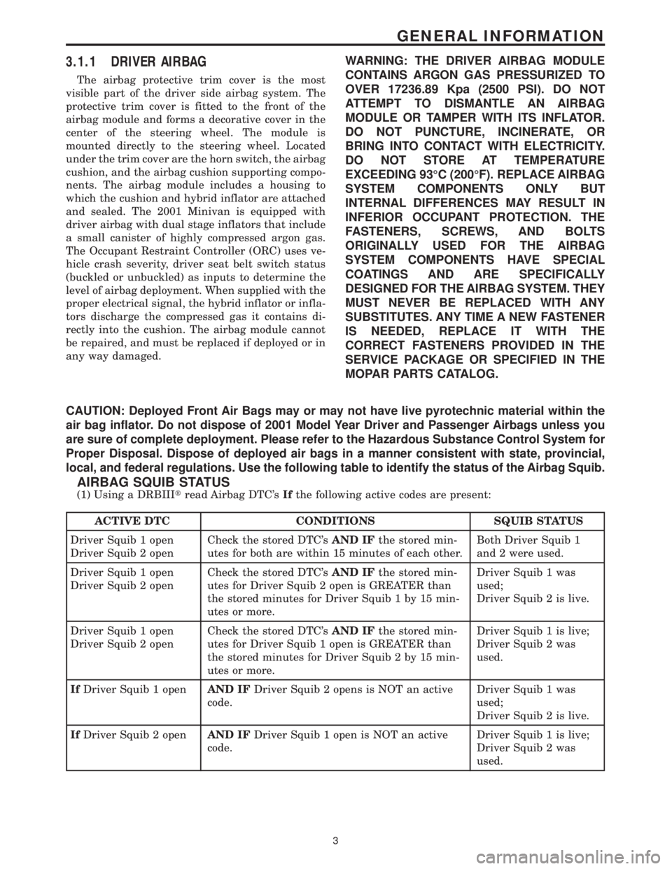
AIRBAG SQUIB STATUS
(1) Using a DRBIIItread Airbag DTC'sIfthe following active codes are present:
ACTIVE DTC CONDITIONS SQUIB STATUS
Driver Squib 1 open
Driver Squib 2 openCheck the stored DTC'sAND IFthe stored min-
utes for both are within 15 minutes of each other.Both Driver Squib 1
and 2 were used.
Driver Squib 1 open
Driver Squib 2 openCheck the stored DTC'sAND IFthe stored min-
utes for Driver Squib 2 open is GREATER than
the stored minutes for Driver Squib 1 by 15 min-
utes or more.Driver Squib 1 was
used;
Driver Squib 2 is live.
Driver Squib 1 open
Driver Squib 2 openCheck the stored DTC'sAND IFthe stored min-
utes for Driver Squib 1 open is GREATER than
the stored minutes for Driver Squib 2 by 15 min-
utes or more.Driver Squib 1 is live;
Driver Squib 2 was
used.
IfDriver Squib 1 openAND IFDriver Squib 2 opens is NOT an active
code.Driver Squib 1 was
used;
Driver Squib 2 is live.
IfDriver Squib 2 openAND IFDriver Squib 1 open is NOT an active
code.Driver Squib 1 is live;
Driver Squib 2 was
used.
3
GENERAL INFORMATION
Page 34 of 4284
CAUTION: Deployed Front Air Bags may or may not have live pyrotechnic material within the
air bag inflator. Do not dispose of 2001 Mopar Year Driver and Passenger Airbags unless you
are sure of complete deployment. Please refer to the Hazardous Substance Control System for
Proper Disposal. Dispose of deployed air bags in a manner consistent with state, provincial,
local, and federal regulations. Use the following table to identify the status of the Airbag Squib.
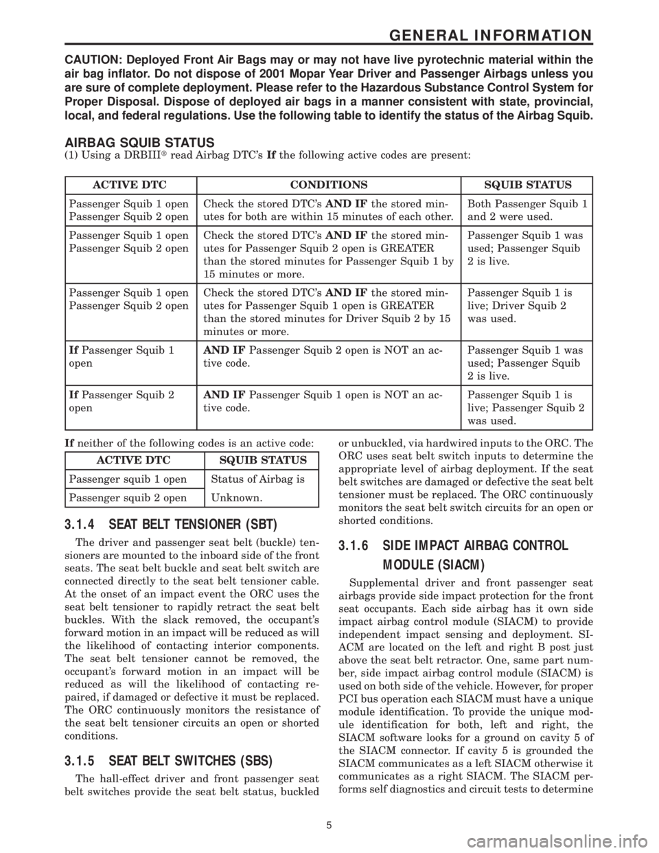
AIRBAG SQUIB STATUS
(1) Using a DRBIIItread Airbag DTC'sIfthe following active codes are present:
ACTIVE DTC CONDITIONS SQUIB STATUS
Passenger Squib 1 open
Passenger Squib 2 openCheck the stored DTC'sAND IFthe stored min-
utes for both are within 15 minutes of each other.Both Passenger Squib 1
and 2 were used.
Passenger Squib 1 open
Passenger Squib 2 openCheck the stored DTC'sAND IFthe stored min-
utes for Passenger Squib 2 open is GREATER
than the stored minutes for Passenger Squib 1 by
15 minutes or more.Passenger Squib 1 was
used; Passenger Squib
2 is live.
Passenger Squib 1 open
Passenger Squib 2 openCheck the stored DTC'sAND IFthe stored min-
utes for Passenger Squib 1 open is GREATER
than the stored minutes for Driver Squib 2 by 15
minutes or more.Passenger Squib 1 is
live; Driver Squib 2
was used.
IfPassenger Squib 1
openAND IFPassenger Squib 2 open is NOT an ac-
tive code.Passenger Squib 1 was
used; Passenger Squib
2 is live.
IfPassenger Squib 2
openAND IFPassenger Squib 1 open is NOT an ac-
tive code.Passenger Squib 1 is
live; Passenger Squib 2
was used.
Ifneither of the following codes is an active code:
ACTIVE DTC SQUIB STATUS
Passenger squib 1 open Status of Airbag is
Passenger squib 2 open Unknown.
3.1.4 SEAT BELT TENSIONER (SBT)
The driver and passenger seat belt (buckle) ten-
sioners are mounted to the inboard side of the front
seats. The seat belt buckle and seat belt switch are
connected directly to the seat belt tensioner cable.
At the onset of an impact event the ORC uses the
seat belt tensioner to rapidly retract the seat belt
buckles. With the slack removed, the occupant's
forward motion in an impact will be reduced as will
the likelihood of contacting interior components.
The seat belt tensioner cannot be removed, the
occupant's forward motion in an impact will be
reduced as will the likelihood of contacting re-
paired, if damaged or defective it must be replaced.
The ORC continuously monitors the resistance of
the seat belt tensioner circuits an open or shorted
conditions.
3.1.5 SEAT BELT SWITCHES (SBS)
The hall-effect driver and front passenger seat
belt switches provide the seat belt status, buckledor unbuckled, via hardwired inputs to the ORC. The
ORC uses seat belt switch inputs to determine the
appropriate level of airbag deployment. If the seat
belt switches are damaged or defective the seat belt
tensioner must be replaced. The ORC continuously
monitors the seat belt switch circuits for an open or
shorted conditions.
3.1.6 SIDE IMPACT AIRBAG CONTROL
MODULE (SIACM)
Supplemental driver and front passenger seat
airbags provide side impact protection for the front
seat occupants. Each side airbag has it own side
impact airbag control module (SIACM) to provide
independent impact sensing and deployment. SI-
ACM are located on the left and right B post just
above the seat belt retractor. One, same part num-
ber, side impact airbag control module (SIACM) is
used on both side of the vehicle. However, for proper
PCI bus operation each SIACM must have a unique
module identification. To provide the unique mod-
ule identification for both, left and right, the
SIACM software looks for a ground on cavity 5 of
the SIACM connector. If cavity 5 is grounded the
SIACM communicates as a left SIACM otherwise it
communicates as a right SIACM. The SIACM per-
forms self diagnostics and circuit tests to determine
5
GENERAL INFORMATION
Page 45 of 4284
the CPA is not properly engaged, a voltage on pin 38
will be interpreted as an unseated connector and a
fault will set.
Flash programming voltage Ð20 volt input on
pin 42. When a DRBIIItis connected and the
proper flash reprogramming sequence is selected,
the 20 volt signal will be applied through pin 42.
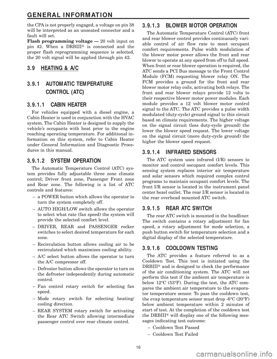
3.9 HEATING & A/C
3.9.1 AUTOMATIC TEMPERATURE
CONTROL (ATC)
3.9.1.1 CABIN HEATER
For vehicles equipped with a diesel engine, a
Cabin Heater is used in conjunction with the HVAC
system. The Cabin Heater is designed to supply the
vehicle's occupants with heat prior to the engine
reaching operating temperature. For additional in-
formation on this system, refer to Cabin Heater
under General Information and Diagnostic Proce-
dures in this manual.
3.9.1.2 SYSTEM OPERATION
The Automatic Temperature Control (ATC) sys-
tem provides fully adjustable three zone climate
control; Driver front zone, Passenger Front zone
and Rear zone. The following is a list of ATC
controls and features:
± a POWER button which allows the operator to
turn the system completely off.
± AUTO HIGH/LOW switch allows the operator
to select what rate (fan speed) the system will
provide the selected comfort level.
± DRIVER, REAR and PASSENGER rocker
switches to select desired temperature for each
zone.
± Recirculation button allows cooling air to be
recirculated which maximizes cooling ability.
± A/C select button allows the operator to turn
the A/C compressor off.
± Defroster button allows the operator to turn on
the defroster independently during automatic
control.
± Fan control rotary switch for selecting fan
speed.
± Mode rotary switch for selecting heating/
cooling direction.
± REAR SYSTEM rotary switch for activating
the Rear ATC Switch allowing intermediate
passenger control over rear climate control.
3.9.1.3 BLOWER MOTOR OPERATION
The Automatic Temperature Control (ATC) front
and rear blower control provides continuously vari-
able control of air flow rate to meet occupant
comfort requirements. Pulse width modulation of
the blower motor power allows the front and rear
blower to operate at any speed from off to full speed.
When front or rear blower operation is required, the
ATC sends a PCI Bus message to the Front Control
Module (FCM) requesting blower relay ON. The
FCM provides a ground for the front and rear
blower motor relay coils, activating both relays. The
front and rear blower relays provide 12 volts to
their respective blower motor power modules. Each
module provides a 12 volt blower motor control
signal to the ATC. The ATC provides a pulse width
modulated (duty-cycle) ground signal to this circuit
based on climate requirements. The higher voltage
on the signal circuit (less duty-cycle ground) the
lower the blower speed request. The lower voltage
on the signal circuit (more duty-cycle ground) the
higher the blower speed request.
3.9.1.4 INFRARED SENSORS
The ATC system uses infrared (I/R) sensors to
monitor and control oocupant comfort levels. This
sensing system replaces interior air temperature
and solar sensors which required complex control
programs to maintain occupant comfort levels. The
front I/R sensor is located in the instrument panel
center bezel outlet. The rear I/R sensor is located in
the rear overhead mounted ATC switch.
3.9.1.5 REAR ATC SWITCH
The rear ATC switch is mounted in the headliner.
The switch contains a rotary adjustment for fan
speed, a rotary adjustment for mode selection, a
push button switch for temperature selection and a
digital display of the selected temperature.
3.9.1.6 COOLDOWN TESTING
The ATC provides a feature referred to as a
Cooldown Test. This test is initiated using the
DRBIIItand is designed to check the performance
of the air conditioning system. The ATC will not
perform this test if the ambient air temperature is
below 12ÉC (53ÉF). During the test, the ATC com-
pares the ambient air temperature to the evapora-
tor temperature sensor. To pass the cooldown test,
the evap temperature sensor must drop -6ÉC (20ÉF)
below ambient temperature within 2 minutes of
start of test. At the completion of the cooldown test
the DRBIIItwill display one of the following mes-
sages indicating test outcome:
± Cooldown Test Passed
± Cooldown Test Failed
16
GENERAL INFORMATION
Page 46 of 4284
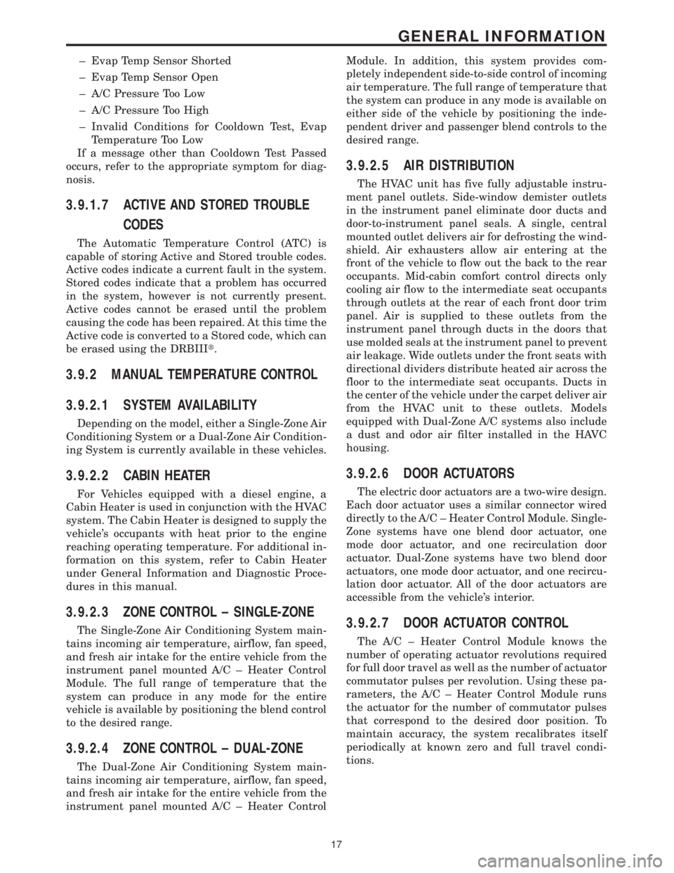
± Evap Temp Sensor Shorted
± Evap Temp Sensor Open
± A/C Pressure Too Low
± A/C Pressure Too High
± Invalid Conditions for Cooldown Test, Evap
Temperature Too Low
If a message other than Cooldown Test Passed
occurs, refer to the appropriate symptom for diag-
nosis.
3.9.1.7 ACTIVE AND STORED TROUBLE
CODES
The Automatic Temperature Control (ATC) is
capable of storing Active and Stored trouble codes.
Active codes indicate a current fault in the system.
Stored codes indicate that a problem has occurred
in the system, however is not currently present.
Active codes cannot be erased until the problem
causing the code has been repaired. At this time the
Active code is converted to a Stored code, which can
be erased using the DRBIIIt.
3.9.2 MANUAL TEMPERATURE CONTROL
3.9.2.1 SYSTEM AVAILABILITY
Depending on the model, either a Single-Zone Air
Conditioning System or a Dual-Zone Air Condition-
ing System is currently available in these vehicles.
3.9.2.2 CABIN HEATER
For Vehicles equipped with a diesel engine, a
Cabin Heater is used in conjunction with the HVAC
system. The Cabin Heater is designed to supply the
vehicle's occupants with heat prior to the engine
reaching operating temperature. For additional in-
formation on this system, refer to Cabin Heater
under General Information and Diagnostic Proce-
dures in this manual.
3.9.2.3 ZONE CONTROL ± SINGLE-ZONE
The Single-Zone Air Conditioning System main-
tains incoming air temperature, airflow, fan speed,
and fresh air intake for the entire vehicle from the
instrument panel mounted A/C ± Heater Control
Module. The full range of temperature that the
system can produce in any mode for the entire
vehicle is available by positioning the blend control
to the desired range.
3.9.2.4 ZONE CONTROL ± DUAL-ZONE
The Dual-Zone Air Conditioning System main-
tains incoming air temperature, airflow, fan speed,
and fresh air intake for the entire vehicle from the
instrument panel mounted A/C ± Heater ControlModule. In addition, this system provides com-
pletely independent side-to-side control of incoming
air temperature. The full range of temperature that
the system can produce in any mode is available on
either side of the vehicle by positioning the inde-
pendent driver and passenger blend controls to the
desired range.
3.9.2.5 AIR DISTRIBUTION
The HVAC unit has five fully adjustable instru-
ment panel outlets. Side-window demister outlets
in the instrument panel eliminate door ducts and
door-to-instrument panel seals. A single, central
mounted outlet delivers air for defrosting the wind-
shield. Air exhausters allow air entering at the
front of the vehicle to flow out the back to the rear
occupants. Mid-cabin comfort control directs only
cooling air flow to the intermediate seat occupants
through outlets at the rear of each front door trim
panel. Air is supplied to these outlets from the
instrument panel through ducts in the doors that
use molded seals at the instrument panel to prevent
air leakage. Wide outlets under the front seats with
directional dividers distribute heated air across the
floor to the intermediate seat occupants. Ducts in
the center of the vehicle under the carpet deliver air
from the HVAC unit to these outlets. Models
equipped with Dual-Zone A/C systems also include
a dust and odor air filter installed in the HAVC
housing.
3.9.2.6 DOOR ACTUATORS
The electric door actuators are a two-wire design.
Each door actuator uses a similar connector wired
directly to the A/C ± Heater Control Module. Single-
Zone systems have one blend door actuator, one
mode door actuator, and one recirculation door
actuator. Dual-Zone systems have two blend door
actuators, one mode door actuator, and one recircu-
lation door actuator. All of the door actuators are
accessible from the vehicle's interior.
3.9.2.7 DOOR ACTUATOR CONTROL
The A/C ± Heater Control Module knows the
number of operating actuator revolutions required
for full door travel as well as the number of actuator
commutator pulses per revolution. Using these pa-
rameters, the A/C ± Heater Control Module runs
the actuator for the number of commutator pulses
that correspond to the desired door position. To
maintain accuracy, the system recalibrates itself
periodically at known zero and full travel condi-
tions.
17
GENERAL INFORMATION
Page 48 of 4284
3.9.2.11 HVAC DIAGNOSTICS
The A/C ± Heater Control Module is fully addres-
sable with the DRBIIIt. Two of the Control Mod-
ule's diagnostic capabilities that the DRBIIItwill
actuate include the A/C Cooldown Test to test A/C
system performance and the HVAC Door Recalibra-
tion Test to determine actuator travel span. After
performing either test, the Control Module will
display one or more messages on the DRBIIIt
screen. The message will indicate either that the
HVAC system passed the test or that there is a fault
currently active in the HVAC system. The DRBIIIt
can also extract active and stored Diagnostic Trou-
ble Codes (DTCs) from the control module. Active
DTCs are faults that currently exit in the HVAC
system. Active DTCs cannot be erased until the
condition causing the code is repaired. Stored DTCs
are faults that occurred in the HVAC system since
the control module received the last ªclear diagnos-
tic infoº message.
3.10 CABIN HEATER
NOTE: The Cabin Heater, also known as the
Diesel Cabin Heater Assist (DCHA), will be
referred to as the DCHA throughout most of
the General Information and the Diagnostic
Procedures in this manual.
3.10.1 GENERAL SAFETY INFORMATION
WARNING: DO NOT OPERATE THE DCHA IN
AN ENCLOSED AREA SUCH AS A GARAGE
THAT DOES NOT HAVE EXHAUST
VENTILATION FACILITIES. ALWAYS VENT
THE DCHA's EXHAUST WHEN OPERATING
THE DCHA. FAILURE TO FOLLOW THESE
INSTRUCTIONS MAY RESULT IN PERSONAL
INJURY OR DEATH.
WARNING: ALLOW THE DCHA ASSEMBLY
TO COOL BEFORE PERFORMING A COM-
PONENT INSPECTION/REPAIR/REPLACE-
MENT. FAILURE TO FOLLOW THESE
INSTRUCTIONS MAY RESULT IN PERSONAL
INJURY.
WARNING: ALWAYS DISCONNECT THE
VEHICLE'S BATTERY PRIOR TO PER-
FORMING ANY TYPE OF WORK ON THE
DCHA. FAILURE TO FOLLOW THESE
INSTRUCTIONS MAY RESULT IN PERSONAL
INJURY OR DEATH.WARNING: NEVER ATTEMPT TO REPAIR THE
DCHA HEATER MODULE OR ANY OF ITS
INTERNAL COMPONENTS. ALWAYS PER-
FORM DCHA COMPONENT REPLACEMENT
IN ACCORDANCE WITH THE SERVICE
INFORMATION. FAILURE TO FOLLOW
THESE INSTRUCTIONS MAY RESULT IN
PERSONAL INJURY OR DEATH.
CAUTION: Do not actuate the DCHA Field
Mode Test with the engine off. Failure to
follow these instructions may result in
internal damage to the DCHA Heater Module.
CAUTION: Always Perform The Cabin Heater
Pre-Test Prior To Performing Any Other Cabin
Heater Test For The Test Result To Be Valid.
NOTE: Do not disconnect the vehicle's
battery or the DCHA's main power-supply
while the DCHA is in operation or in
run-down mode. Failure to follow these
instructions may result in excess emissions
from the DCHA Heater Module.
NOTE: Failure to prime the Dosing Pump
after draining the DCHA fuel line will prevent
DCHA heater activation during the first
attempt to start the heater. This will also set a
Diagnostic Trouble Code (DTC) in the DCHA
Control's memory. Do not perform the Dosing
Pump Priming Procedure if an attempt was
made to start the DCHA without priming the
Dosing Pump first. This will put excess fuel
in the DCHA Heater Module and cause smoke
to emit from the DCHA exhaust pipe when
heater activation occurs.
NOTE: Waxed fuel can obstruct the fuel line
and reduce flow. Check for the appropriate
winter grade fuel and replace as necessary.
3.10.2 COMPONENT DESCRIPTION AND
OPERATION
3.10.2.1 DCHA ASSEMBLY
The DCHA is a supplemental heater designed to
pre-heat the engine's coolant in order to supply the
vehicle's occupants with heat prior to the engine
reaching operating temperature. The DCHA assem-
bly mounts underneath the vehicle on the left side
floor pan near the front door opening. The DCHA
assembly connects to the vehicle's heater hoses and
has a fuel supply line that connects to the vehicle's
fuel tank.
19
GENERAL INFORMATION
Page 49 of 4284
The DCHA assembly consists of a:
²combustion air fan assembly
²burner housing
²burner insert
²control unit/heat exchanger
²combustion chamber
²dosing pump
3.10.2.2 COMBUSTION AIR FAN
The combustion air fan assembly includes the:
²combustion air fan
²combustion air fan inlet
²fuel supply inlet
The combustion air fan delivers the air required
for combustion from the combustion air inlet to the
burner insert.
3.10.2.3 BURNER HOUSING
The burner housing includes the:
²coolant inlet
²coolant outlet
²exhaust outlet
The burner housing accommodates the burner
insert and is combined with the control unit/heat
exchanger as an assembly.
3.10.2.4 BURNER INSERT
The burner insert includes the:
²combustion pipe fuel cross section
²glow plug/flame sensor
Inside the burner insert fuel is distributed across
the combustion pipe fuel cross section. Combustion
of the fuel/air mixture takes place within the com-
bustion pipe to heat the exchanger. The glow plug/
flame sensor located in the burner insert ignites the
fuel/air mixture during heater start up. After heater
start up, the glow plug/flame sensor operates in the
flame sensor function. The glow plug/flame sensor
designed as an electrical resistor is located in the
burner insert opposite the flame side.
3.10.2.5 CONTROL UNIT/HEAT
EXCHANGER
The control unit/heat exchanger includes the:
²control unit
²temperature sensor
²overheat protection
²heat exchanger
²connector terminal
The control unit controls and monitors combus-
tion operation. The control unit is ventilated bymeans of a ventilation hose routed from the com-
bustion air collector compartment of the burner.
The heat exchanger transfers the heat generated by
combustion to the coolant circuit. The control unit/
heat exchanger and the burner housing are an
assembly and must not be disassembled.
The temperature sensor senses the coolant tem-
perature in the heat exchanger as an electrical
resistance. This signal is sent to the control unit for
processing.
The overheat protection, controlled by the tem-
perature resistor, protects the heater against undue
operating temperatures. The overheat protection
will switch the heater off if the water temperature
exceeds 105ÉC (221ÉF).
3.10.2.6 DOSING PUMP
The dosing pump is a combined delivery, dosing,
and shut-off system for the fuel supply of the heater.
The dosing pump receives its supply of fuel from the
vehicle's fuel tank.
3.10.3 OPERATION
3.10.3.1 ACTIVATION
When the ignition is in Run, the FCM monitors
the PCI bus for the Cabin Heater Activation re-
quest. The A/C ± Heater Control Module initiates
this request only when all conditions for Cabin
Heater activation are favorable (see below). The
request carries the status bit that the FCM requires
to activate its Cabin Heater Assist Control Output.
This output is a low side driver (coming from FCM
pin 15) which supplies a ground signal to the Cabin
Heater (pin 5). When the Cabin Heater receives this
ground signal input, it interprets this as an activa-
tion signal. The FCM low side driver is also capable
of diagnostic sensing. The driver will sense an open
circuit when the driver is off, and will sense a short
to voltage when the driver is on. The FCM will set
DTCs for both of these types of faults.
The DCHA will activate only when the:
²engine is running.
²coolant temperature is below 66ÉC (151ÉF).
²fuel tank has greater than 1/8 of a tank of fuel.
²Power switch on the A/C ± Heater Control Module
is on.
²Blend Control on the A/C ± Heater Control Mod-
ule is set above 95% reheat.
²Front Control Module (FCM) sees the Cabin
Heater Activation request that is bussed from the
A/C ± Heater Control Module.
When the DCHA starting sequence begins, the
glow plug and the combustion air fan are activated.
After 30 seconds, the fuel dosing pump begins oper-
20
GENERAL INFORMATION