odometer CHRYSLER VOYAGER 2001 Service Manual
[x] Cancel search | Manufacturer: CHRYSLER, Model Year: 2001, Model line: VOYAGER, Model: CHRYSLER VOYAGER 2001Pages: 4284, PDF Size: 83.53 MB
Page 8 of 4284
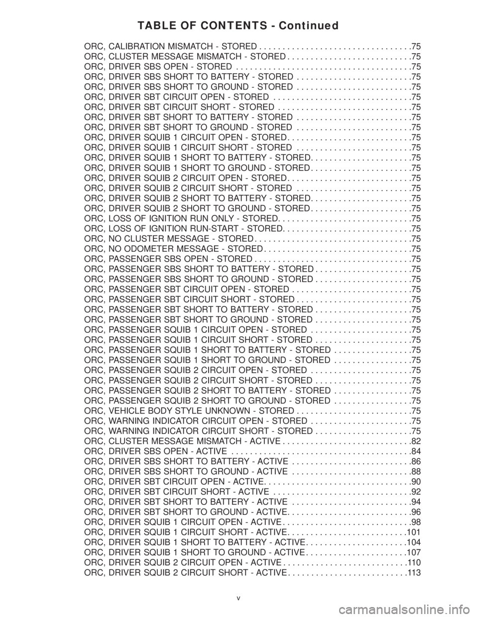
TABLE OF CONTENTS - Continued
ORC, CALIBRATION MISMATCH - STORED.................................75
ORC, CLUSTER MESSAGE MISMATCH - STORED...........................75
ORC, DRIVER SBS OPEN - STORED......................................75
ORC, DRIVER SBS SHORT TO BATTERY - STORED.........................75
ORC, DRIVER SBS SHORT TO GROUND - STORED.........................75
ORC, DRIVER SBT CIRCUIT OPEN - STORED..............................75
ORC, DRIVER SBT CIRCUIT SHORT - STORED.............................75
ORC, DRIVER SBT SHORT TO BATTERY - STORED.........................75
ORC, DRIVER SBT SHORT TO GROUND - STORED.........................75
ORC, DRIVER SQUIB 1 CIRCUIT OPEN - STORED...........................75
ORC, DRIVER SQUIB 1 CIRCUIT SHORT - STORED.........................75
ORC, DRIVER SQUIB 1 SHORT TO BATTERY - STORED......................75
ORC, DRIVER SQUIB 1 SHORT TO GROUND - STORED......................75
ORC, DRIVER SQUIB 2 CIRCUIT OPEN - STORED...........................75
ORC, DRIVER SQUIB 2 CIRCUIT SHORT - STORED.........................75
ORC, DRIVER SQUIB 2 SHORT TO BATTERY - STORED......................75
ORC, DRIVER SQUIB 2 SHORT TO GROUND - STORED......................75
ORC, LOSS OF IGNITION RUN ONLY - STORED.............................75
ORC, LOSS OF IGNITION RUN-START - STORED............................75
ORC, NO CLUSTER MESSAGE - STORED..................................75
ORC, NO ODOMETER MESSAGE - STORED................................75
ORC, PASSENGER SBS OPEN - STORED..................................75
ORC, PASSENGER SBS SHORT TO BATTERY - STORED.....................75
ORC, PASSENGER SBS SHORT TO GROUND - STORED.....................75
ORC, PASSENGER SBT CIRCUIT OPEN - STORED..........................75
ORC, PASSENGER SBT CIRCUIT SHORT - STORED.........................75
ORC, PASSENGER SBT SHORT TO BATTERY - STORED.....................75
ORC, PASSENGER SBT SHORT TO GROUND - STORED.....................75
ORC, PASSENGER SQUIB 1 CIRCUIT OPEN - STORED......................75
ORC, PASSENGER SQUIB 1 CIRCUIT SHORT - STORED.....................75
ORC, PASSENGER SQUIB 1 SHORT TO BATTERY - STORED.................75
ORC, PASSENGER SQUIB 1 SHORT TO GROUND - STORED.................75
ORC, PASSENGER SQUIB 2 CIRCUIT OPEN - STORED......................75
ORC, PASSENGER SQUIB 2 CIRCUIT SHORT - STORED.....................75
ORC, PASSENGER SQUIB 2 SHORT TO BATTERY - STORED.................75
ORC, PASSENGER SQUIB 2 SHORT TO GROUND - STORED.................75
ORC, VEHICLE BODY STYLE UNKNOWN - STORED.........................75
ORC, WARNING INDICATOR CIRCUIT OPEN - STORED......................75
ORC, WARNING INDICATOR CIRCUIT SHORT - STORED.....................75
ORC, CLUSTER MESSAGE MISMATCH - ACTIVE............................82
ORC, DRIVER SBS OPEN - ACTIVE.......................................84
ORC, DRIVER SBS SHORT TO BATTERY - ACTIVE..........................86
ORC, DRIVER SBS SHORT TO GROUND - ACTIVE..........................88
ORC, DRIVER SBT CIRCUIT OPEN - ACTIVE................................90
ORC, DRIVER SBT CIRCUIT SHORT - ACTIVE..............................92
ORC, DRIVER SBT SHORT TO BATTERY - ACTIVE..........................94
ORC, DRIVER SBT SHORT TO GROUND - ACTIVE...........................96
ORC, DRIVER SQUIB 1 CIRCUIT OPEN - ACTIVE............................98
ORC, DRIVER SQUIB 1 CIRCUIT SHORT - ACTIVE..........................101
ORC, DRIVER SQUIB 1 SHORT TO BATTERY - ACTIVE......................104
ORC, DRIVER SQUIB 1 SHORT TO GROUND - ACTIVE......................107
ORC, DRIVER SQUIB 2 CIRCUIT OPEN - ACTIVE...........................110
ORC, DRIVER SQUIB 2 CIRCUIT SHORT - ACTIVE..........................113
v
Page 9 of 4284
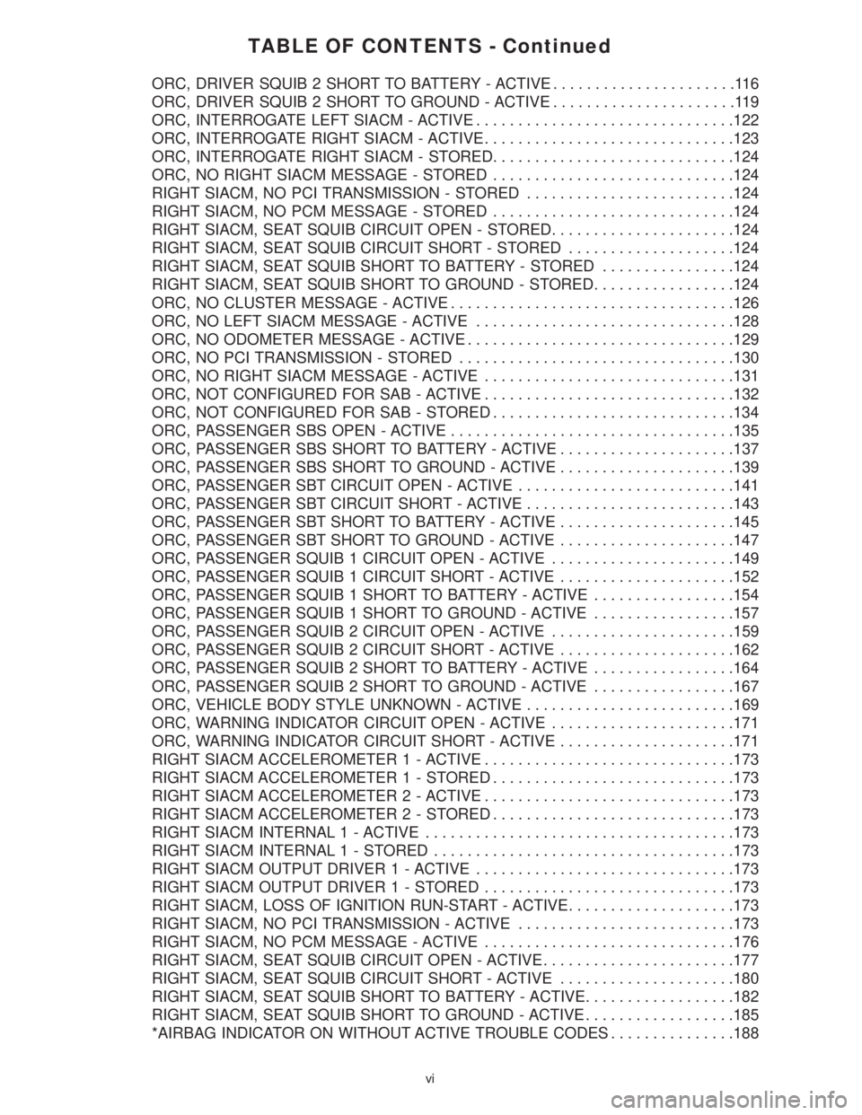
TABLE OF CONTENTS - Continued
ORC, DRIVER SQUIB 2 SHORT TO BATTERY - ACTIVE......................116
ORC, DRIVER SQUIB 2 SHORT TO GROUND - ACTIVE......................119
ORC, INTERROGATE LEFT SIACM - ACTIVE...............................122
ORC, INTERROGATE RIGHT SIACM - ACTIVE..............................123
ORC, INTERROGATE RIGHT SIACM - STORED.............................124
ORC, NO RIGHT SIACM MESSAGE - STORED.............................124
RIGHT SIACM, NO PCI TRANSMISSION - STORED.........................124
RIGHT SIACM, NO PCM MESSAGE - STORED.............................124
RIGHT SIACM, SEAT SQUIB CIRCUIT OPEN - STORED......................124
RIGHT SIACM, SEAT SQUIB CIRCUIT SHORT - STORED....................124
RIGHT SIACM, SEAT SQUIB SHORT TO BATTERY - STORED................124
RIGHT SIACM, SEAT SQUIB SHORT TO GROUND - STORED.................124
ORC, NO CLUSTER MESSAGE - ACTIVE..................................126
ORC, NO LEFT SIACM MESSAGE - ACTIVE...............................128
ORC, NO ODOMETER MESSAGE - ACTIVE................................129
ORC, NO PCI TRANSMISSION - STORED.................................130
ORC, NO RIGHT SIACM MESSAGE - ACTIVE..............................131
ORC, NOT CONFIGURED FOR SAB - ACTIVE..............................132
ORC, NOT CONFIGURED FOR SAB - STORED.............................134
ORC, PASSENGER SBS OPEN - ACTIVE..................................135
ORC, PASSENGER SBS SHORT TO BATTERY - ACTIVE.....................137
ORC, PASSENGER SBS SHORT TO GROUND - ACTIVE.....................139
ORC, PASSENGER SBT CIRCUIT OPEN - ACTIVE..........................141
ORC, PASSENGER SBT CIRCUIT SHORT - ACTIVE.........................143
ORC, PASSENGER SBT SHORT TO BATTERY - ACTIVE.....................145
ORC, PASSENGER SBT SHORT TO GROUND - ACTIVE.....................147
ORC, PASSENGER SQUIB 1 CIRCUIT OPEN - ACTIVE......................149
ORC, PASSENGER SQUIB 1 CIRCUIT SHORT - ACTIVE.....................152
ORC, PASSENGER SQUIB 1 SHORT TO BATTERY - ACTIVE.................154
ORC, PASSENGER SQUIB 1 SHORT TO GROUND - ACTIVE.................157
ORC, PASSENGER SQUIB 2 CIRCUIT OPEN - ACTIVE......................159
ORC, PASSENGER SQUIB 2 CIRCUIT SHORT - ACTIVE.....................162
ORC, PASSENGER SQUIB 2 SHORT TO BATTERY - ACTIVE.................164
ORC, PASSENGER SQUIB 2 SHORT TO GROUND - ACTIVE.................167
ORC, VEHICLE BODY STYLE UNKNOWN - ACTIVE.........................169
ORC, WARNING INDICATOR CIRCUIT OPEN - ACTIVE......................171
ORC, WARNING INDICATOR CIRCUIT SHORT - ACTIVE.....................171
RIGHT SIACM ACCELEROMETER 1 - ACTIVE..............................173
RIGHT SIACM ACCELEROMETER1-STORED.............................173
RIGHT SIACM ACCELEROMETER 2 - ACTIVE..............................173
RIGHT SIACM ACCELEROMETER2-STORED.............................173
RIGHT SIACM INTERNAL 1 - ACTIVE.....................................173
RIGHT SIACM INTERNAL 1 - STORED....................................173
RIGHT SIACM OUTPUT DRIVER 1 - ACTIVE...............................173
RIGHT SIACM OUTPUT DRIVER1-STORED..............................173
RIGHT SIACM, LOSS OF IGNITION RUN-START - ACTIVE....................173
RIGHT SIACM, NO PCI TRANSMISSION - ACTIVE..........................173
RIGHT SIACM, NO PCM MESSAGE - ACTIVE..............................176
RIGHT SIACM, SEAT SQUIB CIRCUIT OPEN - ACTIVE.......................177
RIGHT SIACM, SEAT SQUIB CIRCUIT SHORT - ACTIVE.....................180
RIGHT SIACM, SEAT SQUIB SHORT TO BATTERY - ACTIVE..................182
RIGHT SIACM, SEAT SQUIB SHORT TO GROUND - ACTIVE..................185
*AIRBAG INDICATOR ON WITHOUT ACTIVE TROUBLE CODES...............188
vi
Page 16 of 4284
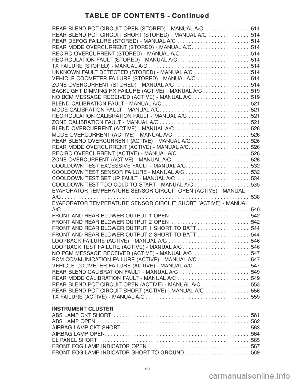
TABLE OF CONTENTS - Continued
REAR BLEND POT CIRCUIT OPEN (STORED) - MANUAL A/C.................514
REAR BLEND POT CIRCUIT SHORT (STORED) - MANUAL A/C...............514
REAR DEFOG FAILURE (STORED) - MANUAL A/C..........................514
REAR MODE OVERCURRENT (STORED) - MANUAL A/C.....................514
RECIRC OVERCURRENT (STORED) - MANUAL A/C.........................514
RECIRCULATION FAULT (STORED) - MANUAL A/C..........................514
TX FAILURE (STORED) - MANUAL A/C....................................514
UNKNOWN FAULT DETECTED (STORED) - MANUAL A/C....................514
VEHICLE ODOMETER FAILURE (STORED) - MANUAL A/C...................514
ZONE OVERCURRENT (STORED) - MANUAL A/C...........................514
BACKLIGHT DIMMING RX FAILURE (ACTIVE) - MANUAL A/C.................519
NO BCM MESSAGE RECEIVED (ACTIVE) - MANUAL A/C....................519
BLEND CALIBRATION FAULT - MANUAL A/C...............................521
MODE CALIBRATION FAULT - MANUAL A/C................................521
RECIRCULATION CALIBRATION FAULT - MANUAL A/C......................521
ZONE CALIBRATION FAULT - MANUAL A/C................................521
BLEND OVERCURRENT (ACTIVE) - MANUAL A/C...........................526
MODE OVERCURRENT (ACTIVE) - MANUAL A/C...........................526
REAR BLEND OVERCURRENT (ACTIVE) - MANUAL A/C.....................526
REAR MODE OVERCURRENT (ACTIVE) - MANUAL A/C......................526
RECIRC OVERCURRENT (ACTIVE) - MANUAL A/C..........................526
ZONE OVERCURRENT (ACTIVE) - MANUAL A/C............................526
COOLDOWN TEST EXCESSIVE FAULT - MANUAL A/C.......................532
COOLDOWN TEST SENSOR FAILURE - MANUAL A/C.......................532
COOLDOWN TEST SET UP FAULT - MANUAL A/C..........................534
COOLDOWN TEST TOO COLD TO START - MANUAL A/C....................535
EVAPORATOR TEMPERATURE SENSOR CIRCUIT OPEN (ACTIVE) - MANUAL
A/C..................................................................538
EVAPORATOR TEMPERATURE SENSOR CIRCUIT SHORT (ACTIVE) - MANUAL
A/C..................................................................540
FRONT AND REAR BLOWER OUTPUT 1 OPEN............................542
FRONT AND REAR BLOWER OUTPUT 2 OPEN............................542
FRONT AND REAR BLOWER OUTPUT 1 SHORT TO BATT...................544
FRONT AND REAR BLOWER OUTPUT 2 SHORT TO BATT...................544
LOOPBACK FAILURE (ACTIVE) - MANUAL A/C.............................546
LOOPBACK TEST FAILURE (ACTIVE) - MANUAL A/C........................546
NO PCM MESSAGE RECEIVED (ACTIVE) - MANUAL A/C....................547
PCM COMMUNICATION FAILURE (ACTIVE) - MANUAL A/C...................547
VEHICLE ODOMETER FAILURE (ACTIVE) - MANUAL A/C....................547
REAR BLEND CALIBRATION FAULT - MANUAL A/C.........................549
REAR MODE CALIBRATION FAULT - MANUAL A/C..........................549
REAR BLEND POT CIRCUIT OPEN (ACTIVE) - MANUAL A/C..................553
REAR BLEND POT CIRCUIT SHORT (ACTIVE) - MANUAL A/C................556
TX FAILURE (ACTIVE) - MANUAL A/C.....................................559
INSTRUMENT CLUSTER
ABS LAMP CKT SHORT................................................561
ABS LAMP OPEN......................................................562
AIRBAG LAMP CKT SHORT.............................................563
AIRBAG LAMP OPEN...................................................564
EL PANEL SHORT.....................................................565
FRONT FOG LAMP INDICATOR OPEN....................................567
FRONT FOG LAMP INDICATOR SHORT TO GROUND.......................569
xiii
Page 50 of 4284
ating and the combustion air fan operation is sus-
pended for 3 seconds. Subsequently, the combustion
air fan speed is increased in two ramps within 56
seconds to nearly full load operation. After a stabi-
lization phase of 15 seconds, the combustion air fan
speed is again increased in a ramp within 50
seconds to nearly full load. After reaching full load
fuel delivery, the glow plug is deactivated and the
combustion air fan operation is increased to full
load. During the subsequent 45 seconds, as well as
in normal operation, the glow plug functions as a
flame sensor to monitor the flame condition. After
all these events, the automatically controlled heat-
ing operation starts.
In case of a no flame or a flame out condition, a
restart is automatically initiated. If the no flame
condition persists, fuel delivery is stopped and the
heater enters an error lockout mode with a run-
down of the combustion air fan. This will set one or
more DTCs in the DCHA Control's memory. If six
continuous attempts to start the heater fail due to
one or more faults in the DCHA system, the heater
enters a heater lockout mode. This will set DTC
B1813 along with any other fault(s) that the DCHA
Control identified.
3.10.3.2 HEATING
During the automatically controlled heating op-
eration, when the coolant temperature reaches
72ÉC (162ÉF), the heater will switch to a part load
operation. When the coolant temperature reaches
75ÉC (167ÉF) or if the heater runs for longer than 76
minutes the heater will switch to a control idle
period. If the coolant temperature drops to 71ÉC
(160ÉF) during a control idle period, the heater will
perform a regular starting sequence into full load
operation. A drop in coolant temperature to 65ÉC
(149ÉF) during part load operation will cause the
heater to switch to a full load operation.
3.10.3.3 DEACTIVATION
The DCHA will deactivate if the:
²engine is turned off.
²coolant temperature reaches 75ÉC (167ÉF).
²heater runs longer than 76 minutes.
²fuel tank has less than 1/8 of a tank of fuel.
²Power switch on the A/C ± Heater Control Module
is off.
²Blend Control on the A/C ± Heater Control Mod-
ule is set below 75% reheat.
When the heater is deactivated, the combustion
stops and a run-down sequence begins. During the
run-down sequence, the combustion air fan contin-
ues operation to cool down the heater. The fan is
automatically switched off after the run-down se-
quence is complete. The run-down time and thecombustion air fan speed depend on the heater
operating condition at the time of deactivation.
Run-down time is approximately 175 seconds when
deactivated in full load operation and approxi-
mately 100 seconds when deactivated in part load
operation.
3.10.4 DIAGNOSTICS
The DCHA is fully addressable with the DRBIIIt.
System tests include a Field Mode Test to activate
the DCHA for diagnostic testing purposes. The
DCHA Control will store up to three DTCs in its
memory. If the Controller detects a new fault in the
DCHA system, one that is not already stored in its
memory, it will clear the oldest of the three stored
DTCs, and it will store the new fault's DTC. If the
Controller detects a reoccurrence of a stored fault, it
will overwrite that fault's DTC with the most recent
occurrence.
3.11 INSTRUMENT CLUSTER
The Instrument Cluster receives and sends mes-
sages to other modules via the PCI bus circuit. The
indicator lamps will illuminate briefly for a bulb
check when the ignition is turned from off to run.
All of the gauges receive their information via the
PCI bus from the powertrain control module and
body control module.
The gauges and the LEDs are not individually
replaceable thereby requiring complete replace-
ment of the Instrument Cluster if a repair is neces-
sary. In the event that the Instrument Cluster loses
communication with other modules on the PCI bus,
the cluster will display ªno busº in the VF display.
The Trip/Reset button is used to switch the dis-
play from trip to total mileage. Holding the button
when the display is in the trip mode will reset the
trip mileage. This button is also used to put the
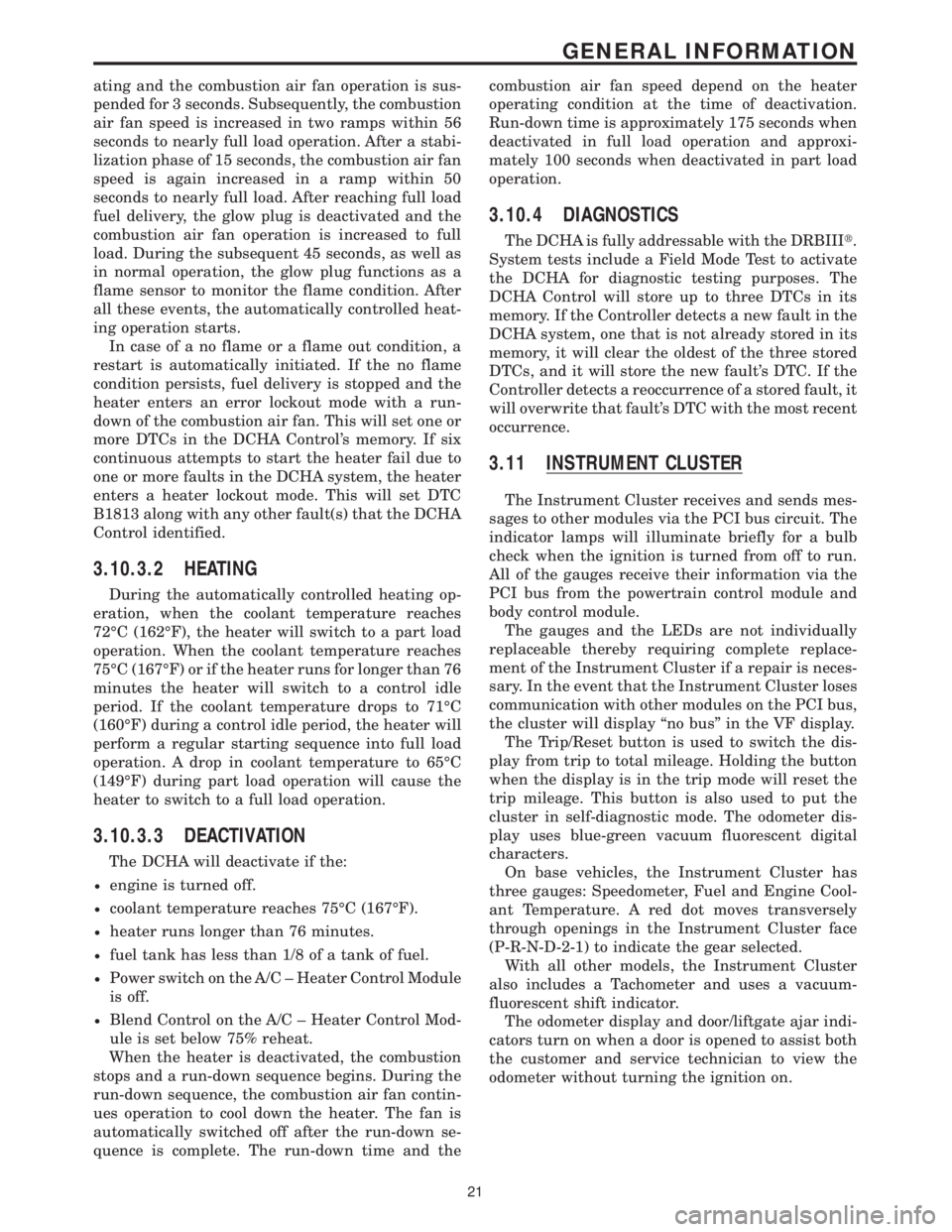
cluster in self-diagnostic mode. The odometer dis-
play uses blue-green vacuum fluorescent digital
characters.
On base vehicles, the Instrument Cluster has
three gauges: Speedometer, Fuel and Engine Cool-
ant Temperature. A red dot moves transversely
through openings in the Instrument Cluster face
(P-R-N-D-2-1) to indicate the gear selected.
With all other models, the Instrument Cluster
also includes a Tachometer and uses a vacuum-
fluorescent shift indicator.
The odometer display and door/liftgate ajar indi-
cators turn on when a door is opened to assist both
the customer and service technician to view the
odometer without turning the ignition on.
21
GENERAL INFORMATION
Page 51 of 4284
On vehicles equipped with AutoStick, the display
includes an O/D OFF indicator that is illuminated
when the driver presses the Overdrive Off button
on the transaxle shifter.
3.11.1 INSTRUMENT CLUSTER SELF TEST
1. Depress and hold the Odometer Reset button.
2. Turn the ignition switch to the RUN/START
position.
3. Release the Odometer reset button.
The Instrument Cluster will illuminate all indi-
cators and step the gauges through several calibra-
tion points. Also, the odometer will display any
stored codes that may have set.
3.11.2 MESSAGE CENTER
The Message Center is located above the brow of
the Instrument Cluster. It houses the following
warning indicators: Check Engine/Service Engine
Soon, high beam, left and right turn signals, Secu-
rity Alarm Set, and low oil pressure. On base
models equipped with the three-speed transaxle,
these indicators appear in the face of the cluster.
The Security Alarm set indicator is a red circle.
Activation of Instrument Cluster indicators is
coordinated with indicators in the message center
and EVIC to avoid redundancy. A revised safety
standard now requires that the seat belt warning
lamp in the Instrument Cluster remain lit if the
driver seat belt is not buckled. A headlamp out ISO
indicator has been added to the Instrument Cluster
to alert the driver when a headlamp is not function-
ing.
3.12 INTERIOR LIGHTING
3.12.1 COURTESY LAMP CONTROL
The body controller has direct control over all of
the vehicle's courtesy lamps. The body computer
will illuminate the courtesy lamps under any of the
following conditions:
1. Any door ajar and courtesy lamp switch on the
headlamp switch is not in the dome off position.
2. The courtesy lamp switch on the headlamp
switch is in the dome on position.
3. A Remote Keyless Entry unlock message is re-
ceived.
4. Driver door unlocked with key (with VTSS only).
3.12.2 ILLUMINATED ENTRY
Illuminated entry will be initiated when the cus-
tomer enters the vehicle by unlocking the doors
with the key fob, or with the key if the vehicle is
equipped with vehicle theft alarm. Upon exiting thevehicle, if the lock button is pressed with a door
open, illuminated entry will cancel when the door
closes. If the doors are closed and the ignition
switch is turned on, the illuminated entry also
cancels. The illuminated entry feature will not
operate if the courtesy lamp switch is in the dome
off position.
3.12.3 INTERIOR LIGHTING BATTERY
SAVER
If any of the interior lamps are left on after the
ignition is turned off, the BCM will turn them off
after 8 minutes. To return to normal operation, the
courtesy lamps will operate after the dome lamp
switch or door ajar switch changes state. The glove
box and switched reading lamps require that the
ignition be turned to the on/acc position.
3.13 MEMORY SYSTEM
The memory system consists of power driver 's
seat, power mirrors and radio presets. The Memory
Seat/Mirror Module (MSMM) is located under the
driver 's seat. It receives input from the following:
driver 's manual 8-way seat switch, driver 's seat
position sensors, PCI bus circuits, and the power
mirror sensors. The module uses these inputs to
perform the following functions: position the driv-
er 's memory seat, both exterior mirrors (during
recalls), and send/receive the memory system infor-
mation over the PCI bus.
The Memory Set Switch is wired to the Body
Control Module (BCM). When a button (either #1 or
#2) is pressed on the set switch causes the to BCM
send a message to the MSMM which in turn sends
a motion status messages to the BCM. If the BCM
receives no motion from the MSMM it will send a
recall message to the MSMM and radio (once igni-
tion is in run or accessory). The MSMM will in turn
position the drivers seat, both mirrors along with
recalling the radio presets. If the drivers seat or
either exterior mirror is inoperative from its own
respective switches, use the service information
and schematic to diagnose the problem. This man-
ual addresses the memory problems only and it is
assumed there is not a basic component failure.
3.13.1 POWER SEAT
The memory power seat provides the driver with
2 position settings for the driver 's seat. Each power
seat motor is connected to the MSMM with two
motor drive circuits. Each circuit is switched be-
tween battery and ground. By being able to bi-
directionally drive the circuits, the MSMM controls
the movement of the motors based on input from
the power seat switch or from the position sensors
when performing a memory recall. Each motor
22
GENERAL INFORMATION
Page 52 of 4284
contains a potentiometer to monitor the seat posi-
tion. To monitor the position of the motor, the
MSMM sends out a 5-volt reference on the sensor
supply circuit. The sensor is grounded back to the
module on a common ground circuit. Based on the
position of the sensor, the MSMM monitors the
voltage change through the sensor on a separate
signal circuit.
The MSMM stores the input value of each of the
four seat potentiometers in memory when the sys-
tem requests a set. The driver can initiate a mem-
ory recall, using either the door mounted memory
switch or the RKE transmitter (if the remote linked
to memory feature is enabled via the EVIC). When
initiated, the MSMM adjusts the four seat sensors
(by using the motors) to match the memorized seat
position data.
For safety, the memory seat recall is disabled by
the MSMM when the vehicle is out of park position
or if the speed is not zero. Any obstruction to seat
movement over a 2-second delay will cause the seat
to stop moving in which case a stalled motor would
be detected by the MSMM and the corresponding
seat output would be deactivated. However, if the
object obstructing the seat is removed, the seat will
function normally again.
3.13.2 MEMORY MIRRORS
Each outside mirror contains vertical and hori-
zontal bi-directional drive positioning motors and
position sensors. The MSMM provides a 5-volt
reference on the signal circuit to each position
sensor. The sensors share a common ground circuit.
The MSMM monitors the position of the mirror
motors by measuring the voltage on each signal
circuit. When a memory position is set, the MSMM
monitors and stores the position of the outside
mirrors. The MSMM adjusts the mirrors to the
appropriate positions when a memory recall mes-
sage is received from the RKE or is requested from
the memory set switch.
The power mirror switch during non-memory
operation operates both mirrors independently of
the MSMM.
3.14 OVERHEAD CONSOLE
3.14.1 COMPASS/MINI-TRIP COMPUTER
(CMTC)
The compass/mini-trip computer is located in the
overhead console. It displays to the driver the
direction the vehicle is traveling and the current
outside temperature, as well as the following trav-
eler navigational information: average fuel econ-
omy (AVG ECO), distance to empty (DTE), instan-
taneous fuel economy (ECO), elapsed time (ET),and trip odometer (ODO). The information needed
for the CMTC functions is received over the PCI bus
from other modules.
3.14.2 ELECTRONIC VEHICLE
INFORMATION CENTER (EVIC)
The Electronic Vehicle Information Center
(EVIC) includes all the same functions and is lo-
cated in the same area as the Compass/Mini-Trip
Computer, but it adds a number of warning mes-
sages. Also, the EVIC messages are spelled out on
the screen, for example, DISTANCE TO EMPTY,
where the Mini-Trip Computer displays only shows
DTE.
If the compass/mini-trip computer or EVIC has
been replaced, it may be necessary to reset the
calibration.
3.14.3 SETTING THE COMPASS
The compass/mini-trip computer and EVIC are
self-calibrated and requires no adjustment. The
word CAL will be displayed to indicate that the
compass is in the fast calibrating mode. CAL will
turn off after the vehicle has gone in three complete
circles without stopping, in an area free of magnetic
disturbance.
If the module displays the temperature while the
compass is blank or shows a false reading, the
vehicle must be demagnetized. See the service man-
ual for the proper procedure.
If the compass still goes blank after the vehicle is
demagnetized, the compass/mini-trip/EVIC module
must be replaced.
3.14.4 SETTING THE VARIANCE
Variance is the difference between magnetic
north and geographic north. To determine the vari-
ance for the area you are in, refer to the following
zone map provided. The number shown for your
area is the variance number for your area.
1. Set the compass/mini-trip computer (CMTC) to
compass/temperature mode.
2. Press and hold down the RESET button for 5
seconds.NOTE:If the button is held for 10
23
GENERAL INFORMATION
Page 59 of 4284
WARNING: BEFORE ROAD TESTING A
VEHICLE, BE SURE THAT ALL
COMPONENTS ARE REASSEMBLED.
DURING THE TEST DRIVE, DO NOT TRY TO
READ THE DRBIIITSCREEN WHILE IN
MOTION. DO NOT HANG THE DRBIIITFROM
THE REAR VIEW MIRROR OR OPERATE IT
YOURSELF. HAVE AN ASSISTANT
AVAILABLE TO OPERATE THE DRBIIIT.
5.0 REQUIRED TOOLS AND
EQUIPMENT
DRBIIIt(diagnostic read-out box)
Jumper wires
Ohmmeter
Voltmeter
Sentry Key Tester
Test Light
8310 Airbag System Load Tool
8443 SRS Airbag System Load Tool
Diagnostic Junction Port Tester 8339
6.0 GLOSSARY OF TERMS
ABSantilock brake system
ACMairbag control module
AECMairbag electronic control module
(ACM)
ASDMairbag system diagnostic module
(ACM)
AT Cautomatic temperature control
BCMbody control module
CABcontroller antilock brake
CMTCcompass/mini-trip computer
CPAconnector positive assurance
DABdriver airbag
DCHAdiesel cabin heater assist
(cabin heater)
DLCdata link connector
DTCdiagnostic trouble code
DRdriver
EBLelectric back lite (rear window de-
fogger)ECMEngine control module
EVICelectronic vehicle information center
FCMfront control module
GCCGulf Coast Countries
HVACheater ventilation, air conditioning
IPMintelligent power module
LDUlower drive unit
LHDLeft Hand Drive
MICmechanical instrument cluster
MTCmanual temperature control
MSMMmemory seat/mirror module
OBDon board diagnostics
ODOodometer
ORCoccupant restraint controller
PA Bpassenger airbag
PASSpassenger
PCIProgrammable Communication In-
terface (vehicle communication bus)
PCMpowertrain control module
PDCpower distribution center
PLGpower liftgate
PLGMpower liftgate module
PSDpower sliding door
PSDMpower sliding door module
PWMpulse width modulated
RHDRight Hand Drive
RKEremote keyless entry
SABseat airbag
SBTseat belt tensioner
SIACMside impact airbag control module
SKIMsentry key immobilizer module
SKISsentry key immobilizer system
SQUIBalso called initiator (located inside
airbag)
SRSsupplemental restraint system
TCMtransmission control module
VFDvacuum fluorescent display
VTSSvehicle theft security system
30
GENERAL INFORMATION
Page 104 of 4284

Symptom List:
ORC, CALIBRATION MISMATCH - STORED
ORC, CLUSTER MESSAGE MISMATCH - STORED
ORC, DRIVER SBS OPEN - STORED
ORC, DRIVER SBS SHORT TO BATTERY - STORED
ORC, DRIVER SBS SHORT TO GROUND - STORED
ORC, DRIVER SBT CIRCUIT OPEN - STORED
ORC, DRIVER SBT CIRCUIT SHORT - STORED
ORC, DRIVER SBT SHORT TO BATTERY - STORED
ORC, DRIVER SBT SHORT TO GROUND - STORED
ORC, DRIVER SQUIB 1 CIRCUIT OPEN - STORED
ORC, DRIVER SQUIB 1 CIRCUIT SHORT - STORED
ORC, DRIVER SQUIB 1 SHORT TO BATTERY - STORED
ORC, DRIVER SQUIB 1 SHORT TO GROUND - STORED
ORC, DRIVER SQUIB 2 CIRCUIT OPEN - STORED
ORC, DRIVER SQUIB 2 CIRCUIT SHORT - STORED
ORC, DRIVER SQUIB 2 SHORT TO BATTERY - STORED
ORC, DRIVER SQUIB 2 SHORT TO GROUND - STORED
ORC, LOSS OF IGNITION RUN ONLY - STORED
ORC, LOSS OF IGNITION RUN-START - STORED
ORC, NO CLUSTER MESSAGE - STORED
ORC, NO ODOMETER MESSAGE - STORED
ORC, PASSENGER SBS OPEN - STORED
ORC, PASSENGER SBS SHORT TO BATTERY - STORED
ORC, PASSENGER SBS SHORT TO GROUND - STORED
ORC, PASSENGER SBT CIRCUIT OPEN - STORED
ORC, PASSENGER SBT CIRCUIT SHORT - STORED
ORC, PASSENGER SBT SHORT TO BATTERY - STORED
ORC, PASSENGER SBT SHORT TO GROUND - STORED
ORC, PASSENGER SQUIB 1 CIRCUIT OPEN - STORED
ORC, PASSENGER SQUIB 1 CIRCUIT SHORT - STORED
ORC, PASSENGER SQUIB 1 SHORT TO BATTERY - STORED
ORC, PASSENGER SQUIB 1 SHORT TO GROUND - STORED
ORC, PASSENGER SQUIB 2 CIRCUIT OPEN - STORED
ORC, PASSENGER SQUIB 2 CIRCUIT SHORT - STORED
ORC, PASSENGER SQUIB 2 SHORT TO BATTERY - STORED
ORC, PASSENGER SQUIB 2 SHORT TO GROUND - STORED
ORC, VEHICLE BODY STYLE UNKNOWN - STORED
ORC, WARNING INDICATOR CIRCUIT OPEN - STORED
ORC, WARNING INDICATOR CIRCUIT SHORT - STORED
Test Note: All symptoms listed above are diagnosed using the same tests.
The title for the tests will be ORC, CALIBRATION MISMATCH
- STORED.
75
AIRBAG
Page 107 of 4284

ORC, DRIVER SQUIB 2 SHORT TO BATTERY - STORED
When Monitored: When the ignition is on, the ORC monitors the voltage of the Driver
Squib 2 circuits.
Set Condition: The ORC has detected high voltage on the Driver Squib 2 circuits.
ORC, DRIVER SQUIB 2 SHORT TO GROUND - STORED
When Monitored: When the ignition is on, the ORC monitors the resistance of the Driver
Squib 2 circuits.
Set Condition: The ORC has detected a short to ground in the Driver Squib 2 circuits.
ORC, LOSS OF IGNITION RUN ONLY - STORED
When Monitored: With the ignition in the run position the ORC monitors the ORC Run
Only Driver circuit for proper system voltage.
Set Condition: If the voltage on the ORC Run Only Driver circuit drops below 4.5 volts,
the code will set.
ORC, LOSS OF IGNITION RUN-START - STORED
When Monitored: With the ignition in the run or start position the ORC monitors the
ORC Run-Start Driver circuit for proper system voltage.
Set Condition: If the voltage on the ORC Run-Start Driver circuit drops below 4.5 volts,
the code will set.
ORC, NO CLUSTER MESSAGE - STORED
When Monitored: With the ignition in the ON position, the ORC monitors the PCI Bus for
a message from the MIC containing the airbag warning lamp status. The MIC transmits
the message one time at ignition on, lamp state change, or in response to the ORC lamp
message.
Set Condition: If the MIC message is not received for 10 consecutive seconds, the code
will set.
ORC, NO ODOMETER MESSAGE - STORED
When Monitored: With ignition on, the ORC monitors the PCI Bus for the Odometer
message from the Body Control Module. The BCM transmits the odometer message at 1
second intervals.
Set Condition: The code will set, if the ORC does not see the odometer message for 10
seconds.
ORC, PASSENGER SBS OPEN - STORED
When Monitored: The ORC monitors the Seat Belt Switch circuit for an open condition.
Set Condition: The code will set if the ORC does not detect the correct circuit voltage.
78
AIRBAG
ORC, CALIBRATION MISMATCH - STORED ÐContinued
Page 158 of 4284
Symptom:
ORC, NO ODOMETER MESSAGE - ACTIVE
When Monitored and Set Condition:
ORC, NO ODOMETER MESSAGE - ACTIVE
When Monitored: With ignition on, the ORC monitors the PCI Bus for the Odometer
message from the Body Control Module. The BCM transmits the odometer message at 1
second intervals.
Set Condition: The code will set, if the ORC does not see the odometer message for 10
seconds.
POSSIBLE CAUSES
BODY CONTROL MODULE COMMUNICATION
ORC, NO ODOMETER MESSAGE
TEST ACTION APPLICABILITY
1 Turn the ignition on.
With the DRB, attempt to communicate with the BCM.
Was the DRB able to I/D or communicate with the BCM?All
Ye s®Go To 2
No®Refer to the Communication category for the related symptom.
Perform AIRBAG VERIFICATION TEST - VER 1.
2WARNING: TURN THE IGNITION OFF, DISCONNECT THE BATTERY AND
WAIT TWO MINUTES BEFORE PROCEEDING.
WARNING: IF THE AIRBAG CONTROL MODULE IS DROPPED AT ANY
TIME, IT MUST BE REPLACED.
If there are no possible causes remaining, view repair.All
Repair
Replace the Airbag Control Module in accordance with Service
Instructions. WARNING: make sure the battery is disconnected
and wait 2 minutes before proceeding.
Perform AIRBAG VERIFICATION TEST - VER 1.
NOTE: When reconnecting airbag system components the Ignition must be
turned off and the Battery must be disconnected.
129
AIRBAG