diagram CHRYSLER VOYAGER 2002 Owners Manual
[x] Cancel search | Manufacturer: CHRYSLER, Model Year: 2002, Model line: VOYAGER, Model: CHRYSLER VOYAGER 2002Pages: 2399, PDF Size: 57.96 MB
Page 1518 of 2399
IGNITION SWITCH
REMOVAL
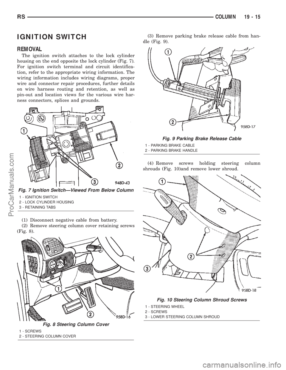
The ignition switch attaches to the lock cylinder
housing on the end opposite the lock cylinder (Fig. 7).
For ignition switch terminal and circuit identifica-
tion, refer to the appropriate wiring information. The
wiring information includes wiring diagrams, proper
wire and connector repair procedures, further details
on wire harness routing and retention, as well as
pin-out and location views for the various wire har-
ness connectors, splices and grounds.
(1) Disconnect negative cable from battery.
(2) Remove steering column cover retaining screws
(Fig. 8).(3) Remove parking brake release cable from han-
dle (Fig. 9).
(4) Remove screws holding steering column
shrouds (Fig. 10)and remove lower shroud.
Fig. 7 Ignition SwitchÐViewed From Below Column
1 - IGNITION SWITCH
2 - LOCK CYLINDER HOUSING
3 - RETAINING TABS
Fig. 8 Steering Column Cover
1 - SCREWS
2 - STEERING COLUMN COVER
Fig. 9 Parking Brake Release Cable
1 - PARKING BRAKE CABLE
2 - PARKING BRAKE HANDLE
Fig. 10 Steering Column Shroud Screws
1 - STEERING WHEEL
2 - SCREWS
3 - LOWER STEERING COLUMN SHROUD
RSCOLUMN19-15
ProCarManuals.com
Page 1519 of 2399
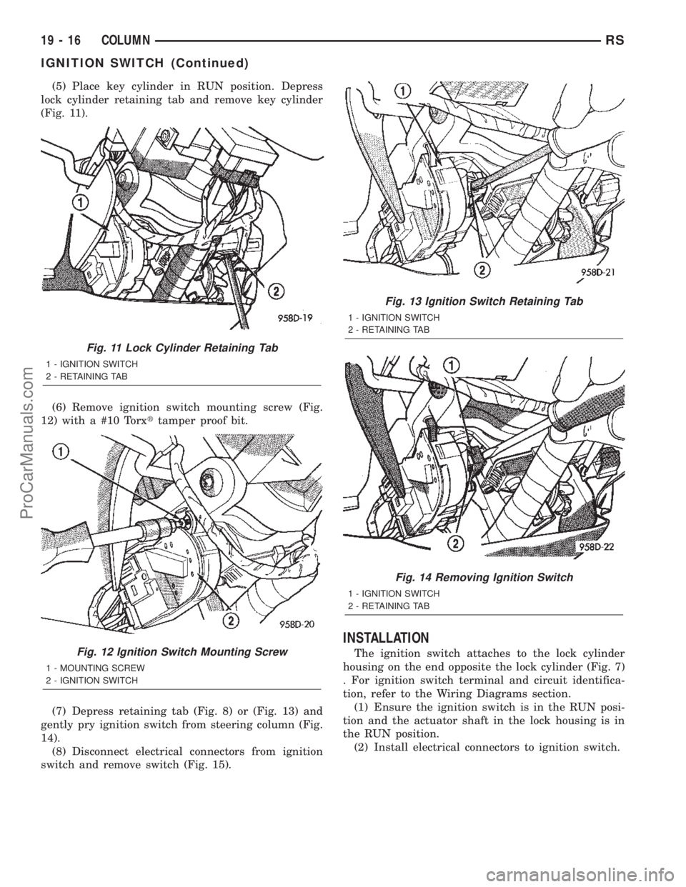
(5) Place key cylinder in RUN position. Depress
lock cylinder retaining tab and remove key cylinder
(Fig. 11).
(6) Remove ignition switch mounting screw (Fig.
12) with a #10 Torxttamper proof bit.
(7) Depress retaining tab (Fig. 8) or (Fig. 13) and
gently pry ignition switch from steering column (Fig.
14).
(8) Disconnect electrical connectors from ignition
switch and remove switch (Fig. 15).
INSTALLATION
The ignition switch attaches to the lock cylinder
housing on the end opposite the lock cylinder (Fig. 7)
. For ignition switch terminal and circuit identifica-
tion, refer to the Wiring Diagrams section.
(1) Ensure the ignition switch is in the RUN posi-
tion and the actuator shaft in the lock housing is in
the RUN position.
(2) Install electrical connectors to ignition switch.
Fig. 11 Lock Cylinder Retaining Tab
1 - IGNITION SWITCH
2 - RETAINING TAB
Fig. 12 Ignition Switch Mounting Screw
1 - MOUNTING SCREW
2 - IGNITION SWITCH
Fig. 13 Ignition Switch Retaining Tab
1 - IGNITION SWITCH
2 - RETAINING TAB
Fig. 14 Removing Ignition Switch
1 - IGNITION SWITCH
2 - RETAINING TAB
19 - 16 COLUMNRS
IGNITION SWITCH (Continued)
ProCarManuals.com
Page 1578 of 2399
31TH AUTOMATIC TRANSAXLE
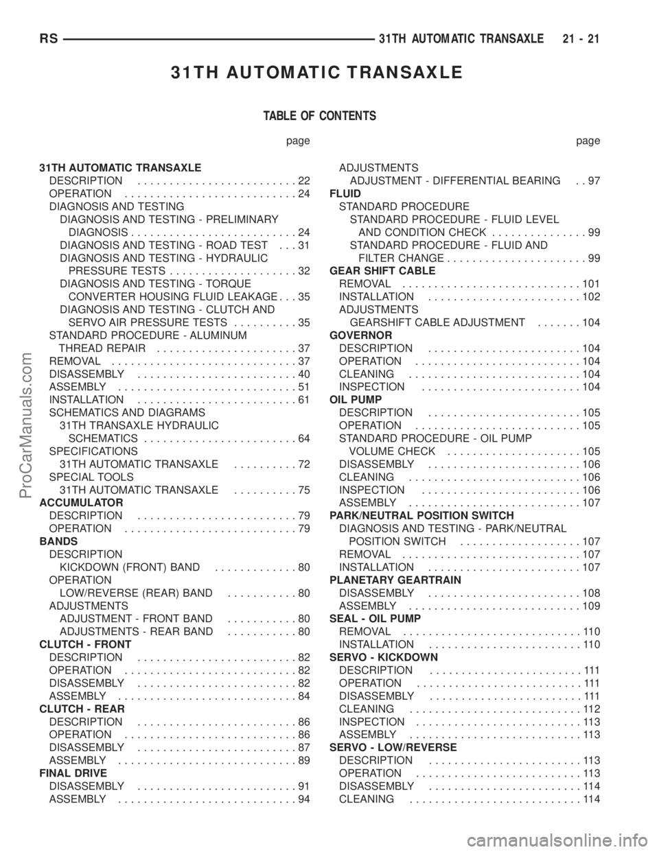
TABLE OF CONTENTS
page page
31TH AUTOMATIC TRANSAXLE
DESCRIPTION.........................22
OPERATION...........................24
DIAGNOSIS AND TESTING
DIAGNOSIS AND TESTING - PRELIMINARY
DIAGNOSIS..........................24
DIAGNOSIS AND TESTING - ROAD TEST . . . 31
DIAGNOSIS AND TESTING - HYDRAULIC
PRESSURE TESTS....................32
DIAGNOSIS AND TESTING - TORQUE
CONVERTER HOUSING FLUID LEAKAGE . . . 35
DIAGNOSIS AND TESTING - CLUTCH AND
SERVO AIR PRESSURE TESTS..........35
STANDARD PROCEDURE - ALUMINUM
THREAD REPAIR......................37
REMOVAL.............................37
DISASSEMBLY.........................40
ASSEMBLY............................51
INSTALLATION.........................61
SCHEMATICS AND DIAGRAMS
31TH TRANSAXLE HYDRAULIC
SCHEMATICS........................64
SPECIFICATIONS
31TH AUTOMATIC TRANSAXLE..........72
SPECIAL TOOLS
31TH AUTOMATIC TRANSAXLE..........75
ACCUMULATOR
DESCRIPTION.........................79
OPERATION...........................79
BANDS
DESCRIPTION
KICKDOWN (FRONT) BAND.............80
OPERATION
LOW/REVERSE (REAR) BAND...........80
ADJUSTMENTS
ADJUSTMENT - FRONT BAND...........80
ADJUSTMENTS - REAR BAND...........80
CLUTCH - FRONT
DESCRIPTION.........................82
OPERATION...........................82
DISASSEMBLY.........................82
ASSEMBLY............................84
CLUTCH - REAR
DESCRIPTION.........................86
OPERATION...........................86
DISASSEMBLY.........................87
ASSEMBLY............................89
FINAL DRIVE
DISASSEMBLY.........................91
ASSEMBLY............................94ADJUSTMENTS
ADJUSTMENT - DIFFERENTIAL BEARING . . 97
FLUID
STANDARD PROCEDURE
STANDARD PROCEDURE - FLUID LEVEL
AND CONDITION CHECK...............99
STANDARD PROCEDURE - FLUID AND
FILTER CHANGE......................99
GEAR SHIFT CABLE
REMOVAL............................101
INSTALLATION........................102
ADJUSTMENTS
GEARSHIFT CABLE ADJUSTMENT.......104
GOVERNOR
DESCRIPTION........................104
OPERATION..........................104
CLEANING...........................104
INSPECTION.........................104
OIL PUMP
DESCRIPTION........................105
OPERATION..........................105
STANDARD PROCEDURE - OIL PUMP
VOLUME CHECK.....................105
DISASSEMBLY........................106
CLEANING...........................106
INSPECTION.........................106
ASSEMBLY...........................107
PARK/NEUTRAL POSITION SWITCH
DIAGNOSIS AND TESTING - PARK/NEUTRAL
POSITION SWITCH...................107
REMOVAL............................107
INSTALLATION........................107
PLANETARY GEARTRAIN
DISASSEMBLY........................108
ASSEMBLY...........................109
SEAL - OIL PUMP
REMOVAL............................110
INSTALLATION........................110
SERVO - KICKDOWN
DESCRIPTION........................111
OPERATION..........................111
DISASSEMBLY........................111
CLEANING...........................112
INSPECTION..........................113
ASSEMBLY...........................113
SERVO - LOW/REVERSE
DESCRIPTION........................113
OPERATION..........................113
DISASSEMBLY........................114
CLEANING...........................114
RS31TH AUTOMATIC TRANSAXLE21-21
ProCarManuals.com
Page 1621 of 2399
SCHEMATICS AND DIAGRAMS
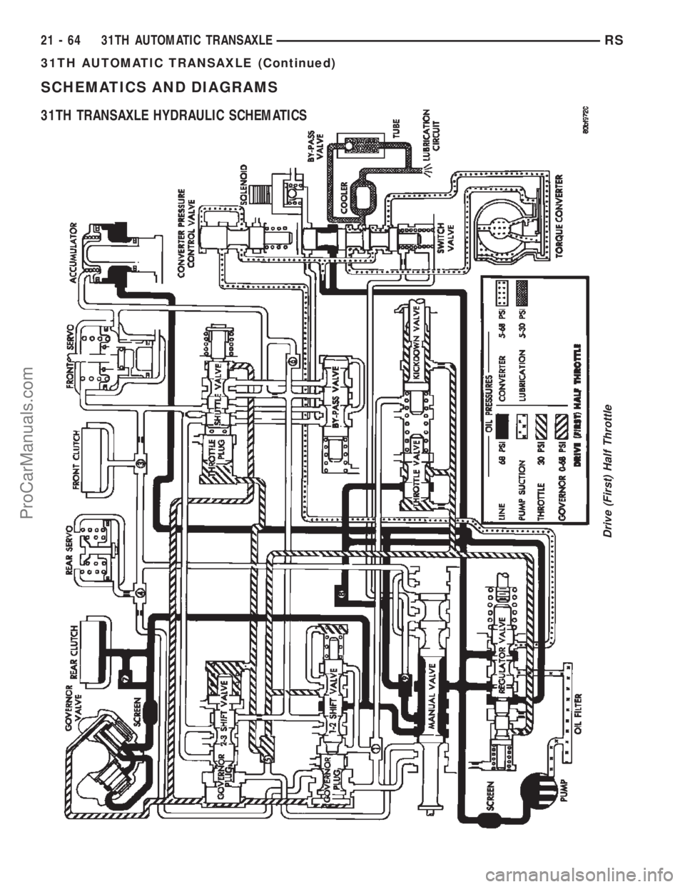
31TH TRANSAXLE HYDRAULIC SCHEMATICS
Drive (First) Half Throttle
21 - 64 31TH AUTOMATIC TRANSAXLERS
31TH AUTOMATIC TRANSAXLE (Continued)
ProCarManuals.com
Page 1718 of 2399
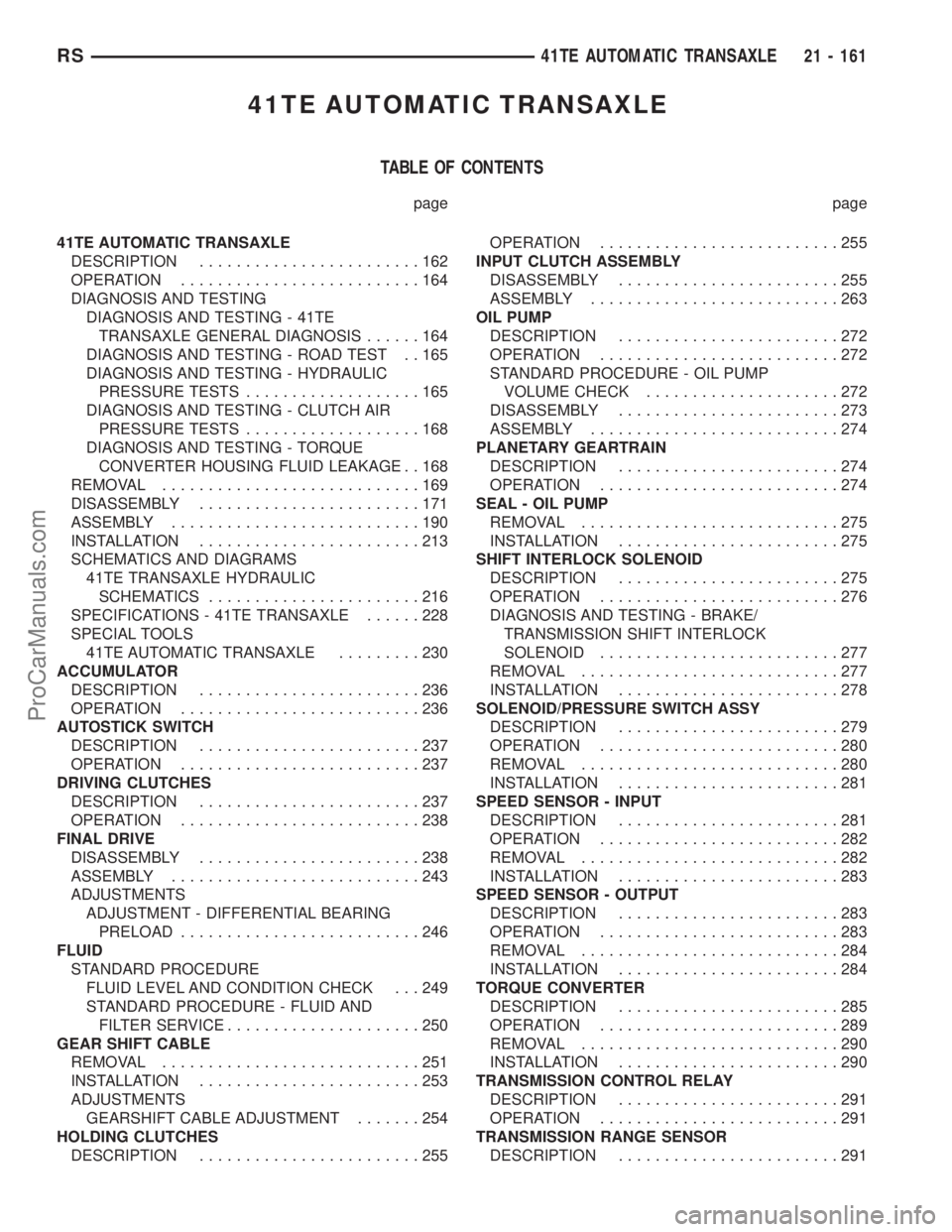
41TE AUTOMATIC TRANSAXLE
TABLE OF CONTENTS
page page
41TE AUTOMATIC TRANSAXLE
DESCRIPTION........................162
OPERATION..........................164
DIAGNOSIS AND TESTING
DIAGNOSIS AND TESTING - 41TE
TRANSAXLE GENERAL DIAGNOSIS......164
DIAGNOSIS AND TESTING - ROAD TEST . . 165
DIAGNOSIS AND TESTING - HYDRAULIC
PRESSURE TESTS...................165
DIAGNOSIS AND TESTING - CLUTCH AIR
PRESSURE TESTS...................168
DIAGNOSIS AND TESTING - TORQUE
CONVERTER HOUSING FLUID LEAKAGE . . 168
REMOVAL............................169
DISASSEMBLY........................171
ASSEMBLY...........................190
INSTALLATION........................213
SCHEMATICS AND DIAGRAMS
41TE TRANSAXLE HYDRAULIC
SCHEMATICS.......................216
SPECIFICATIONS - 41TE TRANSAXLE......228
SPECIAL TOOLS
41TE AUTOMATIC TRANSAXLE.........230
ACCUMULATOR
DESCRIPTION........................236
OPERATION..........................236
AUTOSTICK SWITCH
DESCRIPTION........................237
OPERATION..........................237
DRIVING CLUTCHES
DESCRIPTION........................237
OPERATION..........................238
FINAL DRIVE
DISASSEMBLY........................238
ASSEMBLY...........................243
ADJUSTMENTS
ADJUSTMENT - DIFFERENTIAL BEARING
PRELOAD..........................246
FLUID
STANDARD PROCEDURE
FLUID LEVEL AND CONDITION CHECK . . . 249
STANDARD PROCEDURE - FLUID AND
FILTER SERVICE.....................250
GEAR SHIFT CABLE
REMOVAL............................251
INSTALLATION........................253
ADJUSTMENTS
GEARSHIFT CABLE ADJUSTMENT.......254
HOLDING CLUTCHES
DESCRIPTION........................255OPERATION..........................255
INPUT CLUTCH ASSEMBLY
DISASSEMBLY........................255
ASSEMBLY...........................263
OIL PUMP
DESCRIPTION........................272
OPERATION..........................272
STANDARD PROCEDURE - OIL PUMP
VOLUME CHECK.....................272
DISASSEMBLY........................273
ASSEMBLY...........................274
PLANETARY GEARTRAIN
DESCRIPTION........................274
OPERATION..........................274
SEAL - OIL PUMP
REMOVAL............................275
INSTALLATION........................275
SHIFT INTERLOCK SOLENOID
DESCRIPTION........................275
OPERATION..........................276
DIAGNOSIS AND TESTING - BRAKE/
TRANSMISSION SHIFT INTERLOCK
SOLENOID..........................277
REMOVAL............................277
INSTALLATION........................278
SOLENOID/PRESSURE SWITCH ASSY
DESCRIPTION........................279
OPERATION..........................280
REMOVAL............................280
INSTALLATION........................281
SPEED SENSOR - INPUT
DESCRIPTION........................281
OPERATION..........................282
REMOVAL............................282
INSTALLATION........................283
SPEED SENSOR - OUTPUT
DESCRIPTION........................283
OPERATION..........................283
REMOVAL............................284
INSTALLATION........................284
TORQUE CONVERTER
DESCRIPTION........................285
OPERATION..........................289
REMOVAL............................290
INSTALLATION........................290
TRANSMISSION CONTROL RELAY
DESCRIPTION........................291
OPERATION..........................291
TRANSMISSION RANGE SENSOR
DESCRIPTION........................291
RS41TE AUTOMATIC TRANSAXLE21 - 161
ProCarManuals.com
Page 1773 of 2399
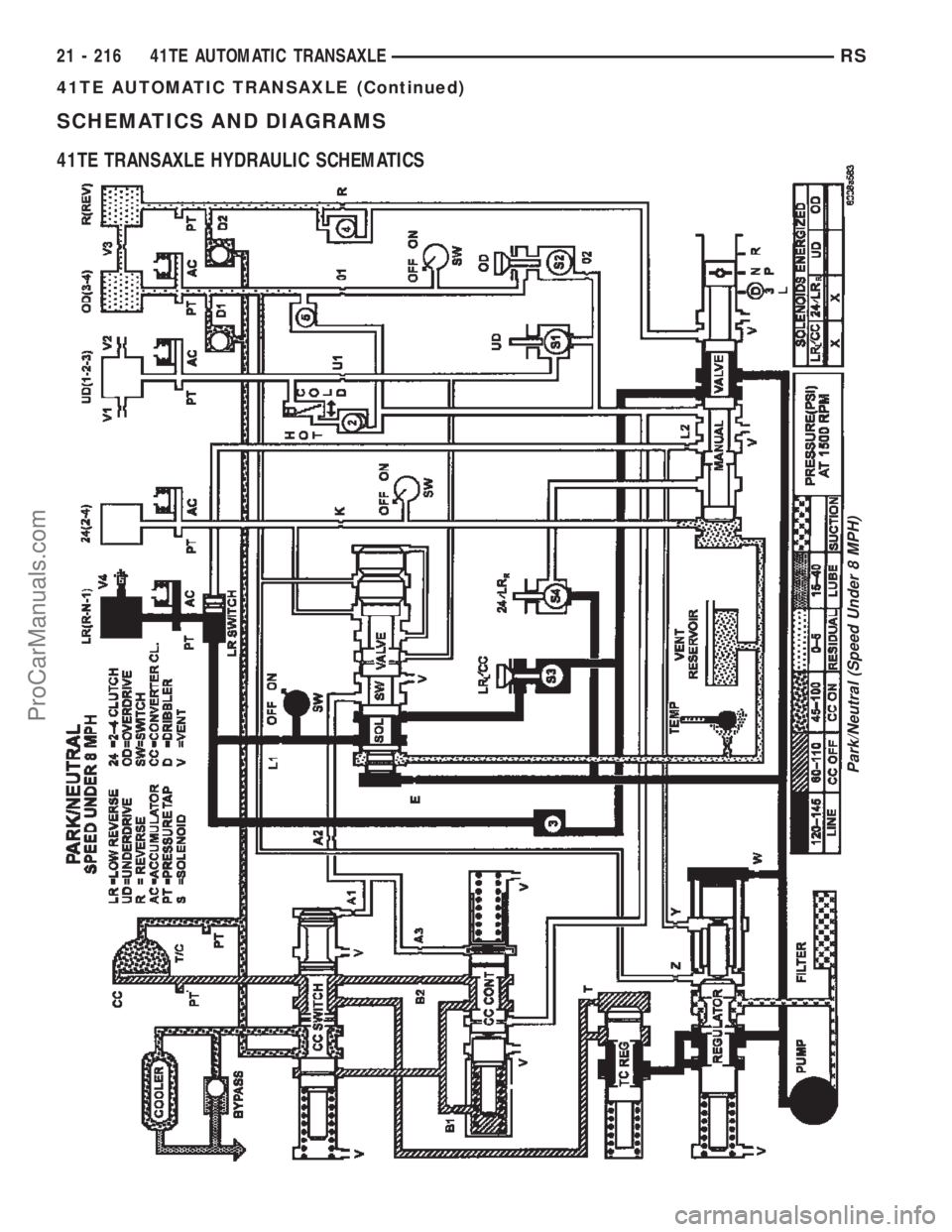
SCHEMATICS AND DIAGRAMS
41TE TRANSAXLE HYDRAULIC SCHEMATICS
Park/Neutral (Speed Under 8 MPH)
21 - 216 41TE AUTOMATIC TRANSAXLERS
41TE AUTOMATIC TRANSAXLE (Continued)
ProCarManuals.com
Page 2257 of 2399
Refer to the appropriate wiring information. The
wiring information includes wiring diagrams, proper
wire and connector repair procedures, further details
on wire harness routing and retention, as well as
pin-out and location views for the various wire har-
ness connectors, splices, and grounds.
DIAGNOSIS AND TESTING - BLOWER MOTOR
RELAY
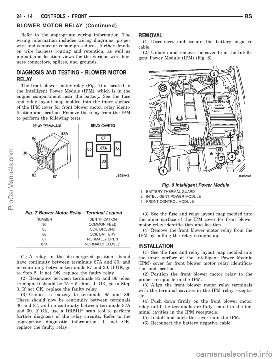
The front blower motor relay (Fig. 7) is located in
the Intelligent Power Module (IPM), which is in the
engine compartment near the battery. See the fuse
and relay layout map molded into the inner surface
of the IPM cover for front blower motor relay identi-
fication and location. Remove the relay from the IPM
to perform the following tests:
(1) A relay in the de-energized position should
have continuity between terminals 87A and 30, and
no continuity between terminals 87 and 30. If OK, go
to Step 2. If not OK, replace the faulty relay.
(2) Resistance between terminals 85 and 86 (elec-
tromagnet) should be 75 5 ohms. If OK, go to Step
3. If not OK, replace the faulty relay.
(3) Connect a battery to terminals 85 and 86.
There should now be continuity between terminals
30 and 87, and no continuity between terminals 87A
and 30. If OK, use a DRBIIItscan tool to perform
further diagnosis of the relay circuits. Refer to the
appropriate diagnostic information. If not OK,
replace the faulty relay.
REMOVAL
(1) Disconnect and isolate the battery negative
cable.
(2) Unlatch and remove the cover from the Intelli-
gent Power Module (IPM) (Fig. 8).
(3) See the fuse and relay layout map molded into
the inner surface of the IPM cover for front blower
motor relay identification and location.
(4) Remove the front blower motor relay from the
IPM by pulling the relay straight up.
INSTALLATION
(1) See the fuse and relay layout map molded into
the inner surface of the Intelligent Power Module
(IPM) cover for front blower motor relay identifica-
tion and location.
(2) Position the front blower motor relay to the
proper receptacle in the IPM.
(3) Align the front blower motor relay terminals
with the terminal cavities in the IPM relay recepta-
cle.
(4) Push down firmly on the front blower motor
relay until the terminals are fully seated in the ter-
minal cavities in the IPM receptacle.
(5) Install and latch the cover onto the IPM.
(6) Reconnect the battery negative cable.
Fig. 7 Blower Motor Relay - Terminal Legend
NUMBER IDENTIFICATION
30 COMMON FEED
85 COIL GROUND
86 COIL BATTERY
87 NORMALLY OPEN
87A NORMALLY CLOSED
Fig. 8 Intelligent Power Module
1 - BATTERY THERMAL GUARD
2 - INTELLIGENT POWER MODULE
3 - FRONT CONTROL MODULE
24 - 14 CONTROLS - FRONTRS
BLOWER MOTOR RELAY (Continued)
ProCarManuals.com
Page 2258 of 2399
BLOWER MOTOR RESISTOR
DESCRIPTION
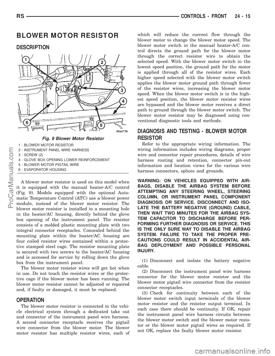
A blower motor resistor is used on this model when
it is equipped with the manual heater-A/C control
(Fig. 9). Models equipped with the optional Auto-
matic Temperature Control (ATC) use a blower power
module, instead of the blower motor resistor. The
blower motor resistor is installed in a mounting hole
in the heater/AC housing, directly behind the glove
box opening of the instrument panel. The resistor
consists of a molded plastic mounting plate with two
integral connector receptacles. Concealed behind the
mounting plate within the heater/AC housing are
four coiled resistor wires contained within a protec-
tive stamped steel cage. The resistor mounting plate
is secured with two screws to the heater/AC housing
and is accessed for service by rolling down the glove
box from the instrument panel.
The blower motor resistor wires will get hot when
in use. Do not touch the resistor wires or the protec-
tive cage if the blower motor has been running. The
blower motor resistor cannot be adjusted or repaired
and, if faulty or damaged, it must be replaced.
OPERATION
The blower motor resistor is connected to the vehi-
cle electrical system through a dedicated take out
and connector of the instrument panel wire harness.
A second connector receptacle receives the pigtail
wire connector from the blower motor. The blower
motor resistor has multiple resistor wires, each ofwhich will reduce the current flow through the
blower motor to change the blower motor speed. The
blower motor switch in the manual heater-A/C con-
trol directs the ground path for the blower motor
through the correct resistor wire to obtain the
selected speed. With the blower motor switch in the
lowest speed position, the ground path for the motor
is applied through all of the resistor wires. Each
higher speed selected with the blower motor switch
applies the blower motor ground path through fewer
of the resistor wires, increasing the blower motor
speed. When the blower motor switch is in the high-
est speed position, the blower motor resistor wires
are bypassed and the blower motor receives a direct
path to ground through the blower motor switch. The
blower motor resistor may be diagnosed using con-
ventional diagnostic tools and methods.
DIAGNOSIS AND TESTING - BLOWER MOTOR
RESISTOR
Refer to the appropriate wiring information. The
wiring information includes wiring diagrams, proper
wire and connector repair procedures, details of wire
harness routing and retention, connector pin-out
information and location views for the various wire
harness connectors, splices and grounds.
WARNING: ON VEHICLES EQUIPPED WITH AIR-
BAGS, DISABLE THE AIRBAG SYSTEM BEFORE
ATTEMPTING ANY STEERING WHEEL, STEERING
COLUMN, OR INSTRUMENT PANEL COMPONENT
DIAGNOSIS OR SERVICE. DISCONNECT AND ISO-
LATE THE BATTERY NEGATIVE (GROUND) CABLE,
THEN WAIT TWO MINUTES FOR THE AIRBAG SYS-
TEM CAPACITOR TO DISCHARGE BEFORE PER-
FORMING FURTHER DIAGNOSIS OR SERVICE. THIS
IS THE ONLY SURE WAY TO DISABLE THE AIRBAG
SYSTEM. FAILURE TO TAKE THE PROPER PRE-
CAUTIONS COULD RESULT IN ACCIDENTAL AIR-
BAG DEPLOYMENT AND POSSIBLE PERSONAL
INJURY.
(1) Disconnect and isolate the battery negative
cable.
(2) Disconnect the instrument panel wire harness
connector for the blower motor resistor and the
blower motor pigtail wire connector from the resistor
connector receptacles.
(3) Check for continuity between each of the
blower motor switch input terminals of the blower
motor resistor and the resistor output terminal. In
each case there should be continuity. If OK, repair
the instrument panel wire harness circuits between
the blower motor switch and the blower motor resis-
tor or the blower motor pigtail wires as required. If
not OK, replace the faulty blower motor resistor.
Fig. 9 Blower Motor Resistor
1 - BLOWER MOTOR RESISTOR
2 - INSTRUMENT PANEL WIRE HARNESS
3 - SCREW (2)
4 - GLOVE BOX OPENING LOWER REINFORCEMENT
5 - BLOWER MOTOR PIGTAIL WIRE
6 - EVAPORATOR HOUSING
RSCONTROLS - FRONT24-15
ProCarManuals.com
Page 2265 of 2399
a battery current output only when the compressor
clutch relay coil is de-energized.
Refer to the appropriate wiring information. The
wiring information includes wiring diagrams, proper
wire and connector repair procedures, further details
on wire harness routing and retention, as well as
pin-out and location views for the various wire har-
ness connectors, splices, and grounds.
DIAGNOSIS AND TESTING - COMPRESSOR
CLUTCH RELAY
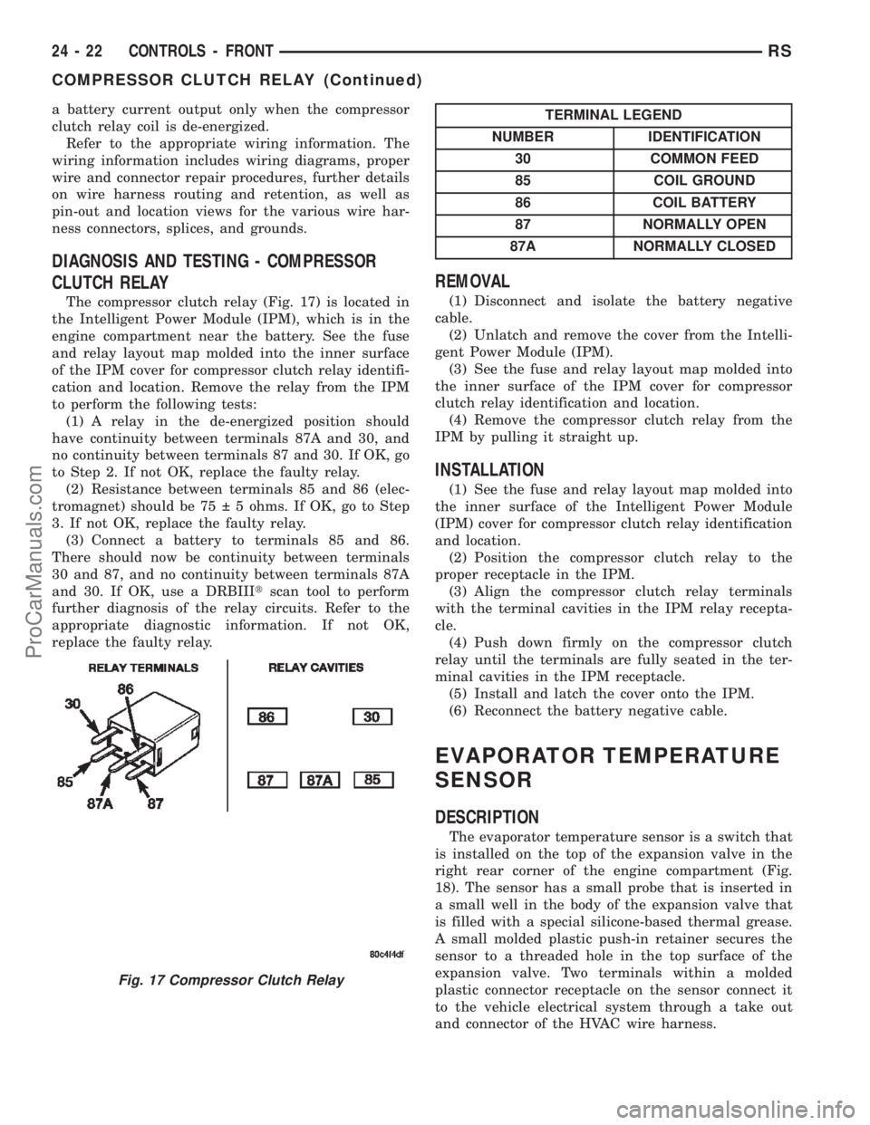
The compressor clutch relay (Fig. 17) is located in
the Intelligent Power Module (IPM), which is in the
engine compartment near the battery. See the fuse
and relay layout map molded into the inner surface
of the IPM cover for compressor clutch relay identifi-
cation and location. Remove the relay from the IPM
to perform the following tests:
(1) A relay in the de-energized position should
have continuity between terminals 87A and 30, and
no continuity between terminals 87 and 30. If OK, go
to Step 2. If not OK, replace the faulty relay.
(2) Resistance between terminals 85 and 86 (elec-
tromagnet) should be 75 5 ohms. If OK, go to Step
3. If not OK, replace the faulty relay.
(3) Connect a battery to terminals 85 and 86.
There should now be continuity between terminals
30 and 87, and no continuity between terminals 87A
and 30. If OK, use a DRBIIItscan tool to perform
further diagnosis of the relay circuits. Refer to the
appropriate diagnostic information. If not OK,
replace the faulty relay.
TERMINAL LEGEND
NUMBER IDENTIFICATION
30 COMMON FEED
85 COIL GROUND
86 COIL BATTERY
87 NORMALLY OPEN
87A NORMALLY CLOSED
REMOVAL
(1) Disconnect and isolate the battery negative
cable.
(2) Unlatch and remove the cover from the Intelli-
gent Power Module (IPM).
(3) See the fuse and relay layout map molded into
the inner surface of the IPM cover for compressor
clutch relay identification and location.
(4) Remove the compressor clutch relay from the
IPM by pulling it straight up.
INSTALLATION
(1) See the fuse and relay layout map molded into
the inner surface of the Intelligent Power Module
(IPM) cover for compressor clutch relay identification
and location.
(2) Position the compressor clutch relay to the
proper receptacle in the IPM.
(3) Align the compressor clutch relay terminals
with the terminal cavities in the IPM relay recepta-
cle.
(4) Push down firmly on the compressor clutch
relay until the terminals are fully seated in the ter-
minal cavities in the IPM receptacle.
(5) Install and latch the cover onto the IPM.
(6) Reconnect the battery negative cable.
EVAPORATOR TEMPERATURE
SENSOR
DESCRIPTION
The evaporator temperature sensor is a switch that
is installed on the top of the expansion valve in the
right rear corner of the engine compartment (Fig.
18). The sensor has a small probe that is inserted in
a small well in the body of the expansion valve that
is filled with a special silicone-based thermal grease.
A small molded plastic push-in retainer secures the
sensor to a threaded hole in the top surface of the
expansion valve. Two terminals within a molded
plastic connector receptacle on the sensor connect it
to the vehicle electrical system through a take out
and connector of the HVAC wire harness.
Fig. 17 Compressor Clutch Relay
24 - 22 CONTROLS - FRONTRS
COMPRESSOR CLUTCH RELAY (Continued)
ProCarManuals.com
Page 2276 of 2399
The blower motor relay terminals are connected to
the vehicle electrical system through a receptacle in
the Intelligent Power Module (IPM). The inputs and
outputs of the compressor clutch relay include:
²The common feed terminal (30) receives a bat-
tery current input from the battery through a B(+)
circuit at all times.
²The coil ground terminal (85) receives a ground
input through the front/rear blower motor relay con-
trol circuit only when the FCM electronically pulls
the control circuit to ground.
²The coil battery terminal (86) receives a battery
current input from the battery through a B(+) circuit
at all times.
²The normally open terminal (87) provides a bat-
tery current output to the blower motor resistor
(manual heater-A/C control) or blower power module
(automatic heater-A/C control) through a fuse in the
IPM on the fused rear blower motor relay output cir-
cuit only when the blower motor relay coil is ener-
gized.
²The normally closed terminal (87A) is not con-
nected to any circuit in this application, but provides
a battery current output only when the blower motor
relay coil is de-energized.
Refer to the appropriate wiring information. The
wiring information includes wiring diagrams, proper
wire and connector repair procedures, further details
on wire harness routing and retention, as well as
pin-out and location views for the various wire har-
ness connectors, splices, and grounds.
DIAGNOSIS AND TESTING - BLOWER MOTOR
RELAY
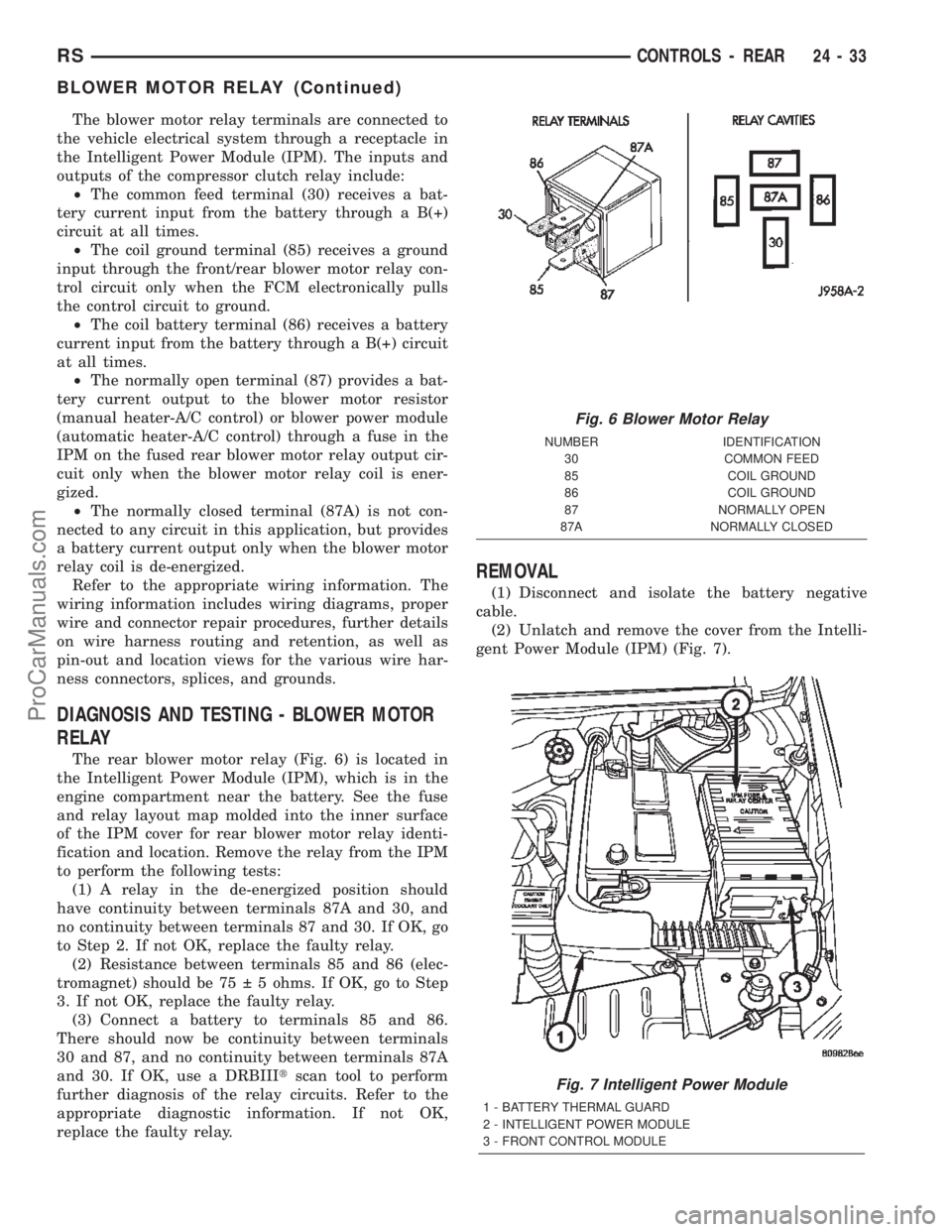
The rear blower motor relay (Fig. 6) is located in
the Intelligent Power Module (IPM), which is in the
engine compartment near the battery. See the fuse
and relay layout map molded into the inner surface
of the IPM cover for rear blower motor relay identi-
fication and location. Remove the relay from the IPM
to perform the following tests:
(1) A relay in the de-energized position should
have continuity between terminals 87A and 30, and
no continuity between terminals 87 and 30. If OK, go
to Step 2. If not OK, replace the faulty relay.
(2) Resistance between terminals 85 and 86 (elec-
tromagnet) should be 75 5 ohms. If OK, go to Step
3. If not OK, replace the faulty relay.
(3) Connect a battery to terminals 85 and 86.
There should now be continuity between terminals
30 and 87, and no continuity between terminals 87A
and 30. If OK, use a DRBIIItscan tool to perform
further diagnosis of the relay circuits. Refer to the
appropriate diagnostic information. If not OK,
replace the faulty relay.
REMOVAL
(1) Disconnect and isolate the battery negative
cable.
(2) Unlatch and remove the cover from the Intelli-
gent Power Module (IPM) (Fig. 7).
Fig. 6 Blower Motor Relay
NUMBER IDENTIFICATION
30 COMMON FEED
85 COIL GROUND
86 COIL GROUND
87 NORMALLY OPEN
87A NORMALLY CLOSED
Fig. 7 Intelligent Power Module
1 - BATTERY THERMAL GUARD
2 - INTELLIGENT POWER MODULE
3 - FRONT CONTROL MODULE
RSCONTROLS - REAR24-33
BLOWER MOTOR RELAY (Continued)
ProCarManuals.com